CL151 GLC Compressor/Limiter/ Gate - Pro Music
CL151 GLC Compressor/Limiter/ Gate - Pro Music
CL151 GLC Compressor/Limiter/ Gate - Pro Music

You also want an ePaper? Increase the reach of your titles
YUMPU automatically turns print PDFs into web optimized ePapers that Google loves.
The plug connected to the Tip is the "Send" which will connect to the Input of the signal<br />
processing device, and the Ring is the "Return" which connects directly to the detector<br />
(compression control) circuit.<br />
Side Chain circuits are often used in "ducking". Ducking is momentarily lowering one signal<br />
under another signal. For example, you may wish to automatically lower a music signal<br />
under a paging microphone signal, then have the music return to normal level after the<br />
page is over. This would be accomplished by running the music into the compressor, and<br />
having the page signal connect into the Side Chain return. The page signal must also be<br />
connected to the main mixer or amplifier as well. When the paging signal begins, its signal<br />
goes to the main mixer and the Side Chain circuitry. The music is compressed or "ducked"<br />
under the page.<br />
SCHEMATIC<br />
ROLLS CORPORATION<br />
SALT LAKE CITY, UTAH<br />
1/04<br />
<strong>CL151</strong> <strong>GLC</strong><br />
<strong>Compressor</strong>/<strong>Limiter</strong>/<br />
<strong>Gate</strong><br />
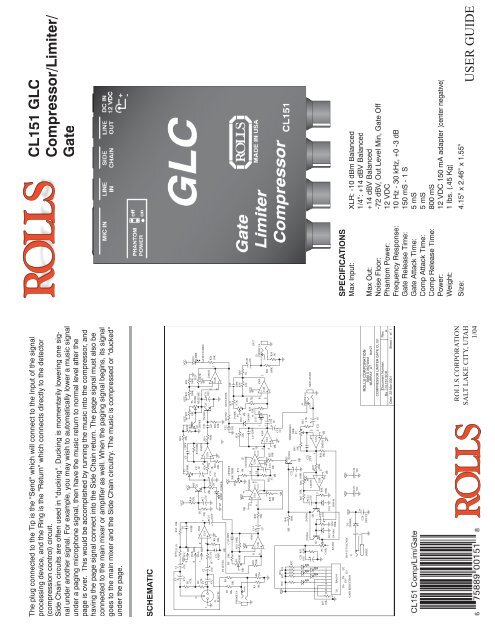
SPECIFICATIONS<br />
Max Input: XLR: -10 dBm Balanced<br />
1/4": +14 dBV Balanced<br />
Max Out: +14 dBV Balanced<br />
Noise Floor: -72 dBV, Out Level Min, <strong>Gate</strong> Off<br />
Phantom Power: 12 VDC<br />
Frequency Response: 10 Hz - 30 kHz, +0 -3 dB<br />
<strong>Gate</strong> Release Time: 150 mS - 1 S<br />
<strong>Gate</strong> Attack Time: 5 mS<br />
Comp Attack Time: 5 mS<br />
Comp Release Time: 800 mS<br />
Power: 12 VDC 150 mA adapter (center negative)<br />
Weight: 1 lbs. (.45 Kg)<br />
Size: 4.15" x 2.46" x 1.55"<br />
USER GUIDE
INTRODUCTION<br />
Thank you for your purchase of the <strong>CL151</strong> <strong>GLC</strong> <strong>Gate</strong> <strong>Compressor</strong> <strong>Limiter</strong>. This unit provides<br />
smooth, soft-knee compression and limiting with a gate. Gain reduction is indicated<br />
via a front panel 5-segment LED bargraph. Plus, the unit has a mic preamp input with 12<br />
volts phantom power available.<br />
WARRANTY INFO<br />
Please visit our website, www.rolls.com, for the Rolls 1 Year Warranty information and<br />
registration.<br />
FRONT PANEL<br />
INPUT: Adjusts the amount of input signal to the <strong>CL151</strong>, from no signal to +20 dB.<br />
GATE REL: This control adjusts the amount of time taken for the gate circuitry to "close" or<br />
mute the output, after the signal level has dropped below the gate Threshold level.<br />
THRESH: Sets the point at which the input signal must surpass to "open" the gate circuitry<br />
or allow signal to pass to the output.<br />
GATE LED: When lit, indicates that the gate is "closed" or the output is muted.<br />
COMP RATIO: This control sets the signal to compression ratio. This ratio relates to the<br />
amount of increase of input compared to output signal. Thus, at a 1:1 ratio, a 1 dB increase<br />
of input signal will result in a 1 dB increase of output signal. At 2:1, a 2 dB increase<br />
of input signal will result in only 1 dB increase of output signal. At 8:1, an 8 dB increase of<br />
input signal will result in a 1dB increase of output signal.<br />
THRESH: Sets the point that the input signal must reach for compression to begin.<br />
GAIN REDUCTION LEDs: This LED ladder indicates the amount of signal compression,<br />
or gain reduction.<br />
OUTPUT: Adjusts the amount of overall output signal from the <strong>CL151</strong>.<br />
PWR: Indicates that the <strong>CL151</strong> is connected to the power source, and the unit is on.<br />
REAR PANEL<br />
MIC IN: Balanced XLR jack, for connection to any standard dynamic or condenser microphone.<br />
LINE IN: Balanced 1/4" TRS jack for connection to balanced or unbalanced line level<br />
signals.<br />
SIDE CHAIN: 1/4" TRS jack for connection via TRS insert cable to a device such as an<br />
equalizer or other device, for direct access to the <strong>CL151</strong> detector circuitry.<br />
LINE OUT: Balanced 1/4" TRS jack for connection to a mixer's line input or to an amplifier.<br />
DC IN: For connection to the Rolls PS27 12 VDC, 150 mA power supply; outside of the<br />
barrel is positive.<br />
SIDE PANEL<br />
PHANTOM POWER: Jumper header for connecting 12 VDC phantom power to the XLR<br />
Mic Input. Phantom power is engaged by carefully removing the jumper, and reconnecting<br />
it to the pins toward the <strong>CL151</strong> controls.<br />
CONNECTION AND OPERATION<br />
The example below shows the connection of a microphone. If the microphone requires<br />
phantom power, make sure the Phantom Power jumper is connecting the two pins closest<br />
to the front panel. Connect the output of the <strong>CL151</strong> via a balanced or unbalanced 1/4"<br />
plug to the input of a mixer or amplifier.<br />
Begin adjustments by setting the INPUT and OUTPUT levels at O (about 10 O'clock). This<br />
setting is for "unity gain".<br />
Set the gate THRESH for "off", the COMP RATIO for 1:1, and the compressor THRESH<br />
for +10. These initial settings essentially bypass the gate and compressor circuits.<br />
The compressor RATIO and THRESH controls work together to control the amount of<br />
compression, and the point at which compression begins respectively. Decreasing the<br />
THRESH control lowers the amount of signal required to begin compression - so it compresses<br />
sooner. This works with the RATIO control which, when increased, increases the<br />
amount of compression.<br />
The gate THRESH control, after being turned slightly counterclockwise from the "off" position,<br />
goes to its maximum level. This means it requires a higher signal level to "open" the<br />
gate. As the gate THRESH control is turned counterclockwise, a lower and lower signal is<br />
required to open the gate.<br />
The gate REL (release time) control sets the amount of time taken for the gate to "close"<br />
after the signal drops below the THRESH level. For example, the <strong>CL151</strong> will continue<br />
passing a sustaining note until the level drops below the THRESH level, and the REL time<br />
has passed.<br />
Connection Example<br />
(Explanation continues on the next page)<br />
USING THE SIDE CHAIN<br />
To access the compressor detector<br />
circuit directly, Rolls has included<br />
a Side Chain jack. The Side Chain<br />
works somewhat like an effects<br />
loop, with a send and return point. A<br />
1/4" Tip-Ring-Sleeve "Insert Cable"<br />
is required to utilize the Side Chain.<br />
See the picture below.

![2 Use the CATEGORY [DEC] / [INC] but - Pro Music](https://img.yumpu.com/43682164/1/190x245/2-use-the-category-dec-inc-but-pro-music.jpg?quality=85)