some aspects of the lifting dynamics of fork lift trucks - Recent Journal
some aspects of the lifting dynamics of fork lift trucks - Recent Journal
some aspects of the lifting dynamics of fork lift trucks - Recent Journal

You also want an ePaper? Increase the reach of your titles
YUMPU automatically turns print PDFs into web optimized ePapers that Google loves.
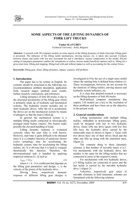
International Conference on Economic Engineering and Manufacturing Systems<br />
Braşov, 25 – 26 November 2009<br />
SOME ASPECTS OF THE LIFTING DYNAMICS OF<br />
FORK LIFT TRUCKS<br />
Yanko SLAVCHEV<br />
Technical University - S<strong>of</strong>ia, Bulgaria<br />
Abstract. A research with 3D computer models on <strong>some</strong> <strong>aspects</strong> <strong>of</strong> <strong>the</strong> <strong><strong>lift</strong>ing</strong> <strong>dynamics</strong> <strong>of</strong> triple telescopic <strong><strong>lift</strong>ing</strong> gears<br />
is presented. The influence <strong>of</strong> <strong>the</strong> <strong><strong>lift</strong>ing</strong> tackle mechanisms, moving masses, etc. is taken into account. Contacts<br />
between chains and tackle rolls are also accounted for and it introduces various complexities to <strong>the</strong> model. Precise<br />
setting <strong>of</strong> integrator parameters enables <strong>the</strong> simulations to realize various model beneficial options such as: <strong><strong>lift</strong>ing</strong> for a<br />
given start time, <strong><strong>lift</strong>ing</strong> and stopping, <strong><strong>lift</strong>ing</strong> load with and without impact as well as accounting for <strong>the</strong> contact forces.<br />
Keywords: <strong><strong>lift</strong>ing</strong> gear, chain, <strong><strong>lift</strong>ing</strong> <strong>dynamics</strong>, impact, contacts, stiff problem<br />
1. Introduction<br />
The paper has to be written in English. Its<br />
contents should be structured in <strong>the</strong> following way<br />
(recommendation): problem description, application<br />
field, research stages, methods used, results,<br />
fur<strong>the</strong>r research, conclusions, and references.<br />
Lifting <strong>dynamics</strong> <strong>of</strong> <strong>fork</strong> <strong>lift</strong> <strong>trucks</strong> is due to<br />
<strong>the</strong> structural peculiarities <strong>of</strong> <strong>the</strong> <strong><strong>lift</strong>ing</strong> gear which<br />
is primarily made up <strong>of</strong> hydraulic and mechanical<br />
systems. The hydraulic system includes one or<br />
more hydraulic drives. After <strong>the</strong> oil is accelerated,<br />
<strong>the</strong> drives act on <strong>the</strong> mechanical system by means<br />
<strong>of</strong> plungers so that <strong>the</strong> load is <strong>lift</strong>ed up.<br />
In general, <strong>the</strong> mechanical system is a<br />
multiple <strong><strong>lift</strong>ing</strong> tackle connected to telescopically<br />
arranged metal frames (masts). The frames make<br />
possible <strong>the</strong> elevated handling <strong>of</strong> loads.<br />
Lifting dynamic response is evaluated<br />
correctly when <strong>the</strong> start time is well known.<br />
However, start time is quite difficult to be obtained<br />
since it is a complex function <strong>of</strong> numerous factors<br />
(valve actuating), time for accelerating <strong>the</strong><br />
hydraulic system, time for accelerating <strong>the</strong> <strong><strong>lift</strong>ing</strong><br />
tackles, etc. It is obvious that it is hard to compute<br />
<strong>the</strong>oretically this function. Therefore, <strong>the</strong><br />
abovementioned task is handled by applying<br />
empirical relations [1, 2] such as<br />
tstart = λv C<br />
(1)<br />
where λ ≈ 6 - 8 is coefficient that depends on<br />
<strong>the</strong> <strong><strong>lift</strong>ing</strong> gear parameters and design; v c is <strong>the</strong><br />
velocity <strong>of</strong> <strong>the</strong> piston <strong>of</strong> <strong>the</strong> hydraulic drive.<br />
Driving force, respectively dynamic<br />
response <strong>of</strong> different <strong><strong>lift</strong>ing</strong> gear designs is<br />
investigated in 0 by <strong>the</strong> use <strong>of</strong> a single mass model<br />
where <strong>the</strong> starting time is defined from relation (1).<br />
These investigations, however, do not account for<br />
<strong>the</strong> elasticity <strong>of</strong> <strong><strong>lift</strong>ing</strong> tackles, moving masses and<br />
hydraulic system influence, etc.<br />
It is clear that detailed research is necessary<br />
on <strong>the</strong> <strong><strong>lift</strong>ing</strong> <strong>dynamics</strong> <strong>of</strong> <strong>fork</strong> <strong>lift</strong> <strong>trucks</strong>.<br />
Well-defined computer simulations that<br />
employ 3-D models are a key to <strong>the</strong> resolution <strong>of</strong><br />
<strong>the</strong>se problems and have been set as <strong>the</strong> objective<br />
to <strong>the</strong> present work.<br />
2. General considerations<br />
Lifting mechanisms with multiple <strong><strong>lift</strong>ing</strong><br />
tackles, embedded in n-telescopic <strong><strong>lift</strong>ing</strong> gears,<br />
could be designed with one or two hydraulic<br />
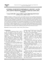
drives. Gears with one drive (gears with low free<br />
<strong>lift</strong>) have <strong>the</strong> hydraulic drive carried by <strong>the</strong><br />
immovable mast as shown in figure 1. Gears with<br />
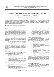
two drives have one <strong>of</strong> <strong>the</strong>ir drives fixed and <strong>the</strong><br />
o<strong>the</strong>r one <strong>lift</strong>s up along with <strong>the</strong> innermost mast,<br />
(figure 2).<br />
The common thing to <strong>the</strong>se kinematic<br />
schemes is that number <strong>of</strong> movable masts is n-1.<br />
For mechanisms with one hydraulic drive, this<br />
number is <strong>the</strong> same for <strong>the</strong> <strong><strong>lift</strong>ing</strong> tackles that are<br />
connected in series to <strong>the</strong> respective masts.<br />
For mechanisms with two hydraulic drives,<br />
n-2 <strong><strong>lift</strong>ing</strong> tackles are connected in series and <strong>the</strong><br />
last tackle is carried by <strong>the</strong> movable hydraulic<br />
drive 1 (figure 2).<br />
Velocities, respectively gear ratios <strong>of</strong><br />
movable elements in both kinematic schemes are<br />
formulated with <strong>the</strong> following relations<br />
RECENT, Vol. 10, no. 3(27), November, 2009 419
<strong><strong>lift</strong>ing</strong> gear with one hydraulic drive<br />
vn−1<br />
= 2vn−2<br />
− vn−3<br />
= [ 2( n − 2) − ( n − 3)<br />
] v1<br />
=<br />
=<br />
( n −1) v1<br />
= ( n −1) v C<br />
Some Aspects <strong>of</strong> <strong>the</strong> Lifting Dynamics <strong>of</strong> Fork Lift Trucks<br />
(2)<br />
Similarly, for <strong>the</strong> payload velocity v Q<br />
vQ<br />
≡ vn<br />
= n ⋅ vC<br />
(3)<br />
The gear ratio is<br />
vQ<br />
in ≡ = n<br />
(4)<br />
vC<br />
so that <strong>the</strong> uniformity <strong>of</strong> hydraulic parameters<br />
during both strokes is conserved.<br />
Both mechanisms have <strong>the</strong> same hydraulic<br />
scheme but <strong>the</strong> difference is that movable drive,<br />
figure 2, needs to be supplied by longer hoses. It<br />
means that, in this case, acceleration time (start<br />
time) for <strong>the</strong> hydraulic system is larger than <strong>the</strong><br />
time for accelerating <strong>the</strong> mechanism in <strong>the</strong><br />
presence <strong>of</strong> one drive. Hydraulic start time could<br />
be calculated with relation [2]:<br />
Figure 1. Lifting gear with one hydraulic drive<br />
1 – hydraulic drive, 2 – multiple <strong><strong>lift</strong>ing</strong> tackle,<br />
n 0 – immovable (fixed) mast, n 1..n-1 – movable masts<br />
<strong><strong>lift</strong>ing</strong> gear with two hydraulic drives<br />
first stroke<br />
vQ = i1v<br />
; i1<br />
= 2<br />
1 C<br />
(5)<br />
second stroke<br />
vQ = i2v<br />
; i2<br />
= n −1<br />
2 C<br />
(6)<br />
On condition that vQ<br />
1<br />
= vQ2<br />
, it follows that<br />
n = 3 ( i1<br />
= i2<br />
)<br />
(7)<br />
Clearly, <strong><strong>lift</strong>ing</strong> gears with two hydraulic<br />
drives have to be designed as triple telescopic<br />
t<br />
Figure 2. Lifting gear with two hydraulic drives<br />
1 – hydraulic drive for working stroke;<br />
2 – hydraulic drive for <strong>the</strong> multiple <strong><strong>lift</strong>ing</strong><br />
tackle,<br />
3 – multiple <strong><strong>lift</strong>ing</strong> tackle;<br />
h 1 , h 2 – working strokes <strong>of</strong> <strong>the</strong> corresponding<br />
hydraulic drives<br />
hydro<br />
start<br />
⎛<br />
⎜<br />
2Ahosel<br />
A<br />
hose<br />
= ⎜ +<br />
⎜ δ<br />
hose<br />
⎜ Ehose<br />
⎝ rhose<br />
vC<br />
AC<br />
γ<br />
⋅<br />
2g<br />
( α A ) 2<br />
fluid<br />
where designations are:<br />
valve<br />
l<br />
tube tube<br />
E<br />
+ A<br />
fluid<br />
l<br />
cyl cyl<br />
⎞<br />
⎟<br />
⎟ ⋅<br />
⎟<br />
⎟<br />
⎠<br />
(8)<br />
420 RECENT, Vol. 10, no. 3(27), November, 2009
Some Aspects <strong>of</strong> <strong>the</strong> Lifting Dynamics <strong>of</strong> Fork Lift Trucks<br />
A, δ, r – cross-sectional area <strong>of</strong> <strong>the</strong> pass, wall<br />
thickness and inner radius; l – length, E fluid ≈ 1.8⋅10 3<br />
MPa – operating fluid modulus <strong>of</strong> elasticity,<br />
E hose = 0.2⋅10 3 MPa - hose modulus <strong>of</strong> elasticity,<br />
γ – operating fluid volumetric weight, α fluid –<br />
coefficient <strong>of</strong> fluid consumption <strong>of</strong> <strong>the</strong> valve,<br />
A valve – cross-sectional area <strong>of</strong> <strong>the</strong> pass <strong>of</strong> <strong>the</strong> valve<br />
3. Generating 3D computer models<br />
The CAD system SolidWorks is employed<br />
to design and assemble <strong>the</strong> geometry <strong>of</strong> two major<br />
3-D models <strong>of</strong> <strong><strong>lift</strong>ing</strong> gears – model with one<br />
hydraulic drive (model 1) and model with two<br />
hydraulic drives (model 2). Real triple telescopic<br />
<strong><strong>lift</strong>ing</strong> gears are modeled and during <strong>the</strong> design<br />
stage, it is strictly monitored that model parameters<br />
such as masses, dimensions, mass moments <strong>of</strong><br />
inertia, etc. conform precisely to <strong>the</strong> real values.<br />
Models are in fact multibody systems <strong>of</strong><br />
rigid bodies 0 that have 94 bodies and 90 degrees<br />
<strong>of</strong> freedom. Models dynamic response is simulated<br />
by MSC.Adams as one <strong>of</strong> <strong>the</strong> most popular<br />
packages suitable exactly for similar problems 0.<br />
Simulations are carried out under <strong>the</strong><br />
following conditions:<br />
• assembly is made <strong>of</strong> steel parts;<br />
• flexible element <strong>of</strong> <strong>the</strong> <strong><strong>lift</strong>ing</strong> tackle is block<br />
chain; contacts between chain members and tackle<br />
rolls are accounted for; chains have <strong>the</strong> same<br />
stiffness;<br />
• gravity is considered;<br />
• contact between payload and actuator (<strong>fork</strong>) as<br />
well as <strong>fork</strong> elasticity is accounted for;<br />
• structural defects as well as friction between<br />
guiding rolls and masts are neglected;<br />
• payload centre <strong>of</strong> mass is located at 500 mm<br />
from <strong>the</strong> base <strong>of</strong> <strong>the</strong> <strong>fork</strong>-arm;<br />
Contacts between chains and tackle rolls as<br />
well as between payload and <strong>the</strong> <strong>fork</strong> arm is a key<br />
aspect <strong>of</strong> <strong>the</strong> simulations. It allows for life-like<br />
models but at <strong>the</strong> same time leads to non-linear<br />
effects and various complexities related to<br />
continuity violations that <strong>the</strong> solution is bound to<br />
account for.<br />
One <strong>of</strong> <strong>the</strong> complexities refers to <strong>the</strong><br />
simulation stepsize. When chains are in motion,<br />
<strong>some</strong> <strong>of</strong> <strong>the</strong> chain members fall in and o<strong>the</strong>rs fall<br />
out <strong>of</strong> contact with <strong>the</strong> tackle rolls which causes<br />
impacts 0. It is a pre-condition for stiff differential<br />
equations and high frequency responses <strong>of</strong> <strong>the</strong><br />
system.<br />
Ano<strong>the</strong>r complexity is related to <strong>the</strong> contact<br />
defined between <strong>the</strong> payload and <strong>the</strong> <strong>fork</strong>. Models<br />
enable simulating cases <strong>of</strong> payload <strong><strong>lift</strong>ing</strong> from <strong>the</strong><br />
ground (<strong>the</strong> payload is 60 mm above <strong>the</strong> ground)<br />
and <strong><strong>lift</strong>ing</strong> from <strong>the</strong> air (<strong>the</strong> payload is located on<br />
<strong>the</strong> <strong>fork</strong>). In <strong>the</strong> cases <strong>of</strong> ground <strong><strong>lift</strong>ing</strong>, impacts<br />
inevitably occur in <strong>the</strong> instant <strong>of</strong> payload picking<br />
up by <strong>the</strong> <strong>fork</strong>. When <strong>the</strong> stepsize is too large,<br />
simulations fail to solve due to integration failures<br />
caused by excessive forces, stability issues and<br />
corrector failures.<br />
Following an iterative procedure, it is<br />
estimated that <strong>the</strong> appropriate stepsize is 1 ms. It<br />
allows for high enough speed <strong>of</strong> solution and at <strong>the</strong><br />
same time not sacrificing <strong>the</strong> precision. It is necessary,<br />
however, to adjust <strong>the</strong> solver settings in details.<br />
The GSTIFF integrator is used as one <strong>of</strong> <strong>the</strong><br />
most popular types <strong>of</strong> stiff multistep integrators.<br />
The small stepsize requires that <strong>the</strong> I3 or SI2 formulation<br />
be selected [5, 6]. In order that relatively<br />
constant stepsize at high order be achieved, <strong>the</strong><br />
following is set: max. integrator timestep = 2.10 -4 s,<br />
local integration tolerance = 10 -2 , max. integrator<br />
order = 12.<br />
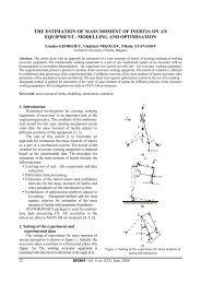
Model actuation is yet ano<strong>the</strong>r complexity.<br />
Hevyside step function is applied to deal with it<br />
(figure 3). This function causes sharp changes in<br />
<strong>the</strong> kinematic parameters, but <strong>the</strong> SI2 formulation<br />
relaxes <strong>the</strong>m and any fur<strong>the</strong>r discontinuities.<br />
Figure 1. Hydraulic drive velocity,<br />
t start = 0.84s, Vc=0.14m/s<br />
The SI2 formulation preserves <strong>the</strong> continuity<br />
<strong>of</strong> derivatives and makes unnecessary any<br />
additional decrease in step size. Moreover, a lifelike<br />
starting <strong>of</strong> <strong>the</strong> model is realized, since <strong>the</strong><br />
steady-state velocity is reached after a certain<br />
period <strong>of</strong> starting time. The same is true for<br />
simulating a working cycle <strong>of</strong> starting, <strong><strong>lift</strong>ing</strong> and<br />
stopping <strong>the</strong> <strong><strong>lift</strong>ing</strong> gear.<br />
Gravity is a must for <strong>the</strong> model. Providing<br />
gravity for <strong>the</strong> model, however, leads to necessary<br />
inertia relaxation prior to model actuation, so that<br />
RECENT, Vol. 10, no. 3(27), November, 2009 421
Some Aspects <strong>of</strong> <strong>the</strong> Lifting Dynamics <strong>of</strong> Fork Lift Trucks<br />
static equilibrium is obtained and additional<br />
undesired impacts are avoided.<br />
A real-life penetration depth <strong>of</strong> 100 µm is<br />
set for <strong>the</strong> contact between tackle rolls and chain<br />
members. It makes <strong>the</strong> system aware <strong>of</strong> <strong>the</strong>ir<br />
presence and relaxes impacts during simulation.<br />
Fur<strong>the</strong>rmore, precise geometry is used for <strong>the</strong> 3D<br />
contacts by setting values <strong>of</strong> <strong>the</strong> scaling factor for<br />
<strong>the</strong> facet tolerance. It decreases errors in forces and<br />
accelerations in contacts. After <strong>the</strong> integrator and<br />
contact settings are adjusted, simulations are<br />
solved and results are measured.<br />
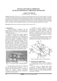
The 3D model <strong>of</strong> a triple telescopic <strong><strong>lift</strong>ing</strong><br />
gear with one hydraulic drive (model 1) is shown<br />
in figure 4.<br />
Figure 2. 3-D model 1<br />
Q n , G f , G t , G 2 , G 1 , G C - weight <strong>of</strong> <strong>the</strong> payload,<br />
<strong>fork</strong>, truck, movable masts and <strong>the</strong> piston <strong>of</strong> <strong>the</strong><br />
hydraulic drive<br />
4. Numerical experiment and analysis<br />
Computer simulations are performed with<br />
both models for <strong>the</strong> following input data:<br />
model 1 Q n = 10kN, G f = 0.7kN, G t = 0.7kN,<br />
G 2 = 0.9kN, G 1 = 1.1kN, G C = 0.3 kN, chain n1 =<br />
30 N (chain has 93 members and step 20mm),<br />
chain n2 = 40N (95 members), chain stiffness k1≈<br />
k2 = 11.62MN/m, c =500mm, c1 = 600mm, m =<br />
60mm;<br />
model 2 all parameters are <strong>the</strong> same as for<br />
model 1 but here <strong>the</strong> weight <strong>of</strong> hydraulic drive 1 is<br />
included as G C1 = 0.3kN. Fork stiffness<br />
(100×40mm) – k <strong>fork</strong> =4.55 MN.m/deg<br />
Hydraulic system parameters are:<br />
A hose =A tube =0.785cm 2 ; r hose =r tube =5mm; l hose =1m;<br />
l tube =2m; δ hose /r hose ≈0.6÷0.7; l cyl =1.4m; A cyl =31cm 2 ;<br />
γ=9kN/m 3 ; α fluid A valve ≈0.02cm 2 (for α fluid =0.6÷0.7);<br />
for model 2, parameters are <strong>the</strong> same and l hose =4m.<br />
Simulations are performed for: <strong><strong>lift</strong>ing</strong> from<br />
<strong>the</strong> ground (case A – sharp <strong>lift</strong>, case B – smooth<br />
<strong>lift</strong>) and <strong><strong>lift</strong>ing</strong> from <strong>the</strong> air (no impact) with<br />
payload velocities v Q =0.3, 0.36, 0.42 and 0.48m/s.<br />
For <strong>the</strong> piston velocities it is obtained: for model 1<br />
from<br />
formula<br />
Error! Reference source not found. at i=3, v ci =<br />
v Q / 3, and <strong>the</strong> start time is defined from<br />
Error! Reference source not found. for λ 1 =6 and<br />
λ 2 =8. These values are listed in Table 1.<br />
Similarly, model 2 parameters are defined<br />
for which velocities in <strong>the</strong> first and second strokes<br />
are equal v c1 = v c2 = v Qi /2. Start times are<br />
determined by:<br />
vQi<br />
tstart1,<br />
2 = ⋅λ1,<br />
2 + ∆t<br />
(9)<br />
2<br />
∆t≈0.3s, is <strong>the</strong> time for accelerating <strong>the</strong> fluid<br />
for <strong>the</strong> longer hydraulic system (drive 1);<br />
Start time <strong>of</strong> <strong>the</strong> second drive is determined<br />
by <strong>the</strong> same formula for ∆t=0.<br />
Table 1 lists data about <strong>the</strong> dynamic<br />
response <strong>of</strong> model 1.<br />
Table 1 – Dynamic response <strong>of</strong> model 1 when <strong>the</strong><br />
payload is <strong>lift</strong>ed from <strong>the</strong> ground<br />
Force [kN] /<br />
t start [s]<br />
/case<br />
v C<br />
[m/s]<br />
0.6<br />
A<br />
0.1<br />
0.8<br />
B<br />
0.72<br />
A<br />
0.12<br />
0.96<br />
B<br />
0.84<br />
A<br />
0.14<br />
1.12<br />
B<br />
0.96<br />
A<br />
0.16<br />
1.28<br />
B<br />
static<br />
force [kN]<br />
Dynamic coefficients<br />
drive chain n1 chain n2<br />
66.27 42.84 20.49<br />
1.81 1.81 1.8<br />
66.07 42.76 20.46<br />
1.80 1.8 1.79<br />
72.30 47.08 22.62<br />
1.97 1.98 1.99<br />
70.32 45.16 21.63<br />
1.92 1.91 1.91<br />
74.09 49.08 23.56<br />
2.02 2.07 2.07<br />
68.35 46.01 22.11<br />
1.86 1.94 1.94<br />
76.68 50.14 24.05<br />
2.09 2.11 2.11<br />
71.01 46.29 22.20<br />
1.94 1.95 1.95<br />
36.68 23.75 11.38<br />
Figures 5 to 7 shows chain responses for<br />
model 1. Figure 8 and 9 show chain responses for<br />
model 2. Figure 8 illustrates contact forces in chain<br />
422 RECENT, Vol. 10, no. 3(27), November, 2009
Some Aspects <strong>of</strong> <strong>the</strong> Lifting Dynamics <strong>of</strong> Fork Lift Trucks<br />
members P and R. Figure 10 gives chain force for<br />
model1, case A in <strong>the</strong> event <strong>of</strong> sharp stopping.<br />
Figure 3. Forces in chains n1 and n2, model 1,<br />
case B, v c =0.1m/s<br />
Figure 6. Forces in chains n1 and n2, model 2, <strong><strong>lift</strong>ing</strong><br />
with impact, t start =1.5s, v c =0.15m/s<br />
Figure 4. Forces in chain n1, model 1,<br />
cases A and B, v c =0.16m/s<br />
Figure 7. Forces in chain n1 and chain members P and<br />
R, model 2 <strong><strong>lift</strong>ing</strong> with impact, t start =1.5s, Vc=0.15m/s<br />
Figure 5. Forces in chain n1, model 1, <strong><strong>lift</strong>ing</strong> with and<br />
without impact, case B, v c =0.16m/s<br />
Figure 8. Force in chain n1, model 1, case A,<br />
sharp stopping t stop =0.1s<br />
RECENT, Vol. 10, no. 3(27), November, 2009 423
Some Aspects <strong>of</strong> <strong>the</strong> Lifting Dynamics <strong>of</strong> Fork Lift Trucks<br />
The corresponding values <strong>of</strong> <strong>the</strong><br />
fundamental natural frequencies <strong>of</strong> <strong>the</strong> models are<br />
ν1=3.2 Hz – for model 1 and ν1=4.78 Hz – for<br />
model 2.<br />
It is established from results analyses that<br />
<strong>the</strong> dynamic response <strong>of</strong> forces in chains and drive<br />
is identical regardless <strong>of</strong> <strong><strong>lift</strong>ing</strong> velocities. When<br />
<strong>the</strong> payload is <strong>lift</strong>ed from <strong>the</strong> ground, model1, <strong>the</strong><br />
dynamic response is 50% higher compared to <strong>the</strong><br />
case when <strong>the</strong> payload is located on <strong>the</strong> <strong>fork</strong> and<br />
<strong>the</strong>n <strong>lift</strong>ed up. Model 1 has shown a dynamic<br />
response that is 17% higher than in model 2.<br />
Beating effects are observed in case B at<br />
higher <strong><strong>lift</strong>ing</strong> velocities but <strong>the</strong>se are quickly<br />
dissipated. The reason for <strong>the</strong> effects is found in<br />
<strong>the</strong> external loading behaviour – Heavyside step<br />
function.<br />
Contact forces in chain members passing<br />
over <strong>the</strong> tackle rolls are to be noticed. As shown in<br />
figure 9, members P and R are loaded differently.<br />
Member P is in contact with <strong>the</strong> roll at <strong>the</strong> instant<br />
<strong>of</strong> max. force in <strong>the</strong> chain and <strong>the</strong>refore this<br />
member turns out to be <strong>the</strong> one with <strong>the</strong> highest<br />
loading. In ano<strong>the</strong>r instant (t=2.39s), when member<br />
Q is in contact with <strong>the</strong> roll, it is clear that this<br />
o<strong>the</strong>r member is not loaded as high.<br />
Besides, when members pass over <strong>the</strong> roll,<br />
transversal vibrations occur with amplitude <strong>of</strong><br />
0.3÷0.5mm. These cause high frequency vibrations<br />
in <strong>the</strong> range 20 ÷ 30 Hz.<br />
Analyzing figure 10 results has proved that<br />
<strong><strong>lift</strong>ing</strong> and sharp stopping have <strong>the</strong> same effect on<br />
<strong>the</strong> dynamic response <strong>of</strong> <strong>the</strong> system.<br />
References<br />
1. Slavchev, Tzv.: Regarding selection <strong>of</strong> <strong><strong>lift</strong>ing</strong> velocities <strong>of</strong><br />
<strong>fork</strong> <strong>lift</strong> <strong>trucks</strong>. International Conference, Plovdiv, 1982<br />
2. Wecksler, V.М., Mouha, Т.I.: Design and analyses <strong>of</strong><br />
materials handling machines. Mechanical Engineering.<br />
1971<br />
3. Slavchev, Tzv.: R&D <strong>of</strong> <strong><strong>lift</strong>ing</strong> gears <strong>of</strong> <strong>fork</strong> <strong>lift</strong> <strong>trucks</strong>.<br />
Dissertation <strong>the</strong>sis, 1986<br />
4. ***: MSC.Adams Help documentation<br />
5. Brenan, K.E., Campbell, S.L, Petzold, L.R.: Numerical<br />
Solution <strong>of</strong> Initial-Value Problems in Differential-<br />
Algebraic Equations (Classics in Applied Ma<strong>the</strong>matics,<br />
14). Society for Industrial & Applied Ma<strong>the</strong>matics, ISBN<br />
0-89871-353-6, Philadelphia, USA, 1996<br />
6. Orlandea, N.V.: A study <strong>of</strong> <strong>the</strong> effects <strong>of</strong> <strong>the</strong> lower index<br />
methods on ADAMS sparse tableau formulation for <strong>the</strong><br />
computational <strong>dynamics</strong> <strong>of</strong> multi-body mechanical systems.<br />
<strong>Journal</strong> <strong>of</strong> Multi-body Dynamics, Vol. 213, No. 1, 1999, p.<br />
1-9, ISSN 1464-4193, London UK<br />
7. Johnson, K.L.: Contact Mechanics. Cambridge University<br />
Press, ISBN 0-521-34796-3, London UK, 2001<br />
8. Roberson, R.E., Schwertassek, R.: Dynamics <strong>of</strong> Multibody<br />
Systems. Springer-Verlag, ISBN 0-387-17447-8, Berlin,<br />
Germany, 1998<br />
424 RECENT, Vol. 10, no. 3(27), November, 2009