Sections 1 and 2
Sections 1 and 2
Sections 1 and 2

Create successful ePaper yourself
Turn your PDF publications into a flip-book with our unique Google optimized e-Paper software.
Name:__________________________________<br />
Number:___________________<br />
Spring 2010<br />
CPE231 Digital Logic<br />
Section 1<br />
Quiz 3-A<br />
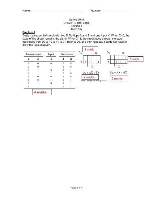
Problem 1<br />
Design a sequential circuit with two D flip-flops A <strong>and</strong> B <strong>and</strong> one input X. When X=0, the<br />
state of the circuit remains the same. When X=1, the circuit goes through the state<br />
transitions from 00 to 10 to 11 to 01, back to 00, <strong>and</strong> then repeats. You do not have to<br />
draw the logic diagram.<br />
1 mark<br />
1 mark<br />
2 marks<br />
2 marks<br />
4 marks<br />
Page 1 of 1
Name:__________________________________<br />
Number:___________________<br />
Spring 2010<br />
CPE231 Digital Logic<br />
Section 1<br />
Quiz 3-B<br />
Problem 1<br />
Design a sequential circuit with two D flip-flops A <strong>and</strong> B <strong>and</strong> one input X. When X=1, the<br />
state of the circuit remains the same. When X=0, the circuit goes through the state<br />
transitions from 00 to 11 to 01 to 10, back to 00, <strong>and</strong> then repeats. You do not have to<br />
draw the logic diagram.<br />
Present state Input Next state<br />
A B X A B<br />
0 0 0 1 1<br />
0 0 1 0 0<br />
0 1 0 1 0<br />
0 1 1 0 1<br />
1 0 0 0 0<br />
1 0 1 1 0<br />
1 1 0 0 1<br />
1 1 1 1 1<br />
4 marks<br />
DA<br />
A<br />
B<br />
1 1<br />
1 1<br />
X<br />
1 mark<br />
DA=AX+A'X'<br />
2 marks<br />
DB<br />
A<br />
B<br />
1 1<br />
1 1<br />
X<br />
1 mark<br />
DB=AB+BX+A'B'X'<br />
2 marks<br />
Page 1 of 1
Name:__________________________________<br />
Number:___________________<br />
Spring 2010<br />
CPE231 Digital Logic<br />
Section 2 ; Quiz 3-A<br />
A serial leading 0’s detector is to be designed. A binary integer of arbitrary length is presented to the<br />
serial leading 0’s detector, most significant bit first, on input X. When a given bit is presented on input X,<br />
the corresponding output bit is to appear during the same clock cycle on output Z. As long as the bits<br />
applied to X are 1, Z = 1. When the first 0 is applied to X, Z = 0. For all bit values applied to X after the<br />
first 0 is applied, Z = 1. To indicate that a sequence is complete <strong>and</strong> that the circuit is to be initialized to<br />
receive another sequence, input Y becomes 1 for one clock cycle. Otherwise, Y is 0.<br />
(a) Find the state diagram for the serial leading 0’s detector.<br />
(b) Find the state table for the serial leading 0’s detector.<br />
a.<br />
b.<br />
A(present<br />
state)<br />
X Y A(next<br />
state)<br />
0 0 0 1 0<br />
0 0 1 0 0<br />
0 1 0 0 1<br />
0 1 1 0 1<br />
1 0 0 1 1<br />
1 0 1 0 1<br />
1 1 0 1 1<br />
1 1 1 0 1<br />
Z<br />
Page 1 of 1
Name:__________________________________<br />
Number:___________________<br />
Spring 2010<br />
CPE231 Digital Logic<br />
Section 2 ; Quiz 3-B<br />
Problem<br />
A communication network link requires a circuit that produces the sequence 01111110. You are to<br />
design a synchronous sequential circuit that starts producing this sequence for input E = 1. Once the<br />
sequence starts, it completes. If E = 1, during the last output in the sequence, the sequence repeats.<br />
Otherwise, if E 0, the output remains constant at 0.<br />
(a) Draw the Moore state diagram for the circuit.<br />
(b) Find the state table <strong>and</strong> make a state assignment.<br />
a.<br />
b.<br />
D2D1D0 E=0 E=1 Z<br />
000 001 001 0<br />
001 010 010 1<br />
010 011 011 1<br />
011 100 100 1<br />
100 101 101 1<br />
101 110 110 1<br />
110 111 111 1<br />
111 111 000 0<br />
Page 1 of 1


![Problem 1: Loop Unrolling [18 points] In this problem, we will use the ...](https://img.yumpu.com/36629594/1/184x260/problem-1-loop-unrolling-18-points-in-this-problem-we-will-use-the-.jpg?quality=85)