ISSN : 2277-1328 (Online) - ISRM
ISSN : 2277-1328 (Online) - ISRM
ISSN : 2277-1328 (Online) - ISRM

You also want an ePaper? Increase the reach of your titles
YUMPU automatically turns print PDFs into web optimized ePapers that Google loves.
6 <strong>ISRM</strong> (India) Journal<br />
drive closure are plotted in Figure 3. This shows<br />
representative, underlying inwards wall movement versus<br />
model step in the 1/10 footprint sub model at 3 key<br />
locations in the sub model; a drawpoint, crosscut and<br />
drawpoint intersection. Note that the specific location was<br />
selected in the basis of expected large deformation and<br />
that the model is calibrated using measured drive closure.<br />
Almost all of the rest of the footprint shows much lower<br />
expected drive closure. The model indicates that at this<br />
selected location, with effective TH or universal beam<br />
support, up to 255-300 mm of closure is eventually<br />
expected after propagation of the cave.<br />
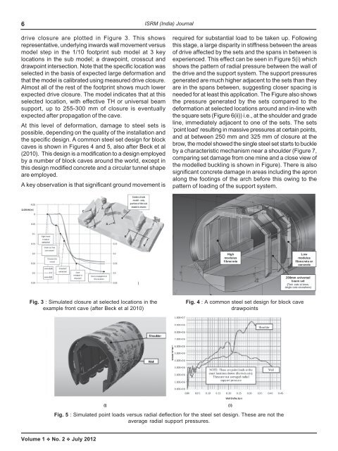
At this level of deformation, damage to steel sets is<br />
possible, depending on the quality of the installation and<br />
the specific design. A common steel set design for block<br />
caves is shown in Figures 4 and 5, also after Beck et al<br />
(2010). This design is a modification to a design employed<br />
by a number of block caves around the world, except in<br />
this design modified concrete and a circular tunnel shape<br />
are employed.<br />
A key observation is that significant ground movement is<br />
required for substantial load to be taken up. Following<br />
this stage, a large disparity in stiffness between the areas<br />
of drive affected by the sets and the spans in between is<br />
experienced. This effect can be seen in Figure 5(i) which<br />
shows the pattern of radial pressure between the wall of<br />
the drive and the support system. The support pressures<br />
generated are much higher adjacent to the sets than they<br />
are in the spans between, suggesting closer spacing is<br />
needed for at least this application. The Figure also shows<br />
the pressure generated by the sets compared to the<br />
deformation at selected locations around and in-line with<br />
the square sets (Figure 6(ii)) i.e., at the shoulder and grade<br />
line, immediately adjacent to one of the sets. The sets<br />
‘point load’ resulting in massive pressures at certain points,<br />
and at between 250 mm and 325 mm of closure at the<br />
brow, the model showed the single steel set starts to buckle<br />
by a characteristic mechanism near a shoulder (Figure 7,<br />
comparing set damage from one mine and a close view of<br />
the modelled buckling is shown in Figure). There is also<br />
significant concrete damage in areas including the apron<br />
along the footings of the arch before this owing to the<br />
pattern of loading of the support system.<br />
Fig. 3 : Simulated closure at selected locations in the<br />
example front cave (after Beck et al 2010)<br />
Fig. 4 : A common steel set design for block cave<br />
drawpoints<br />
Fig. 5 : Simulated point loads versus radial deflection for the steel set design. These are not the<br />
average radial support pressures.<br />
Volume 1 No. 2 July 2012