
You also want an ePaper? Increase the reach of your titles
YUMPU automatically turns print PDFs into web optimized ePapers that Google loves.
<strong>technical</strong><br />
<strong>sheet</strong><br />
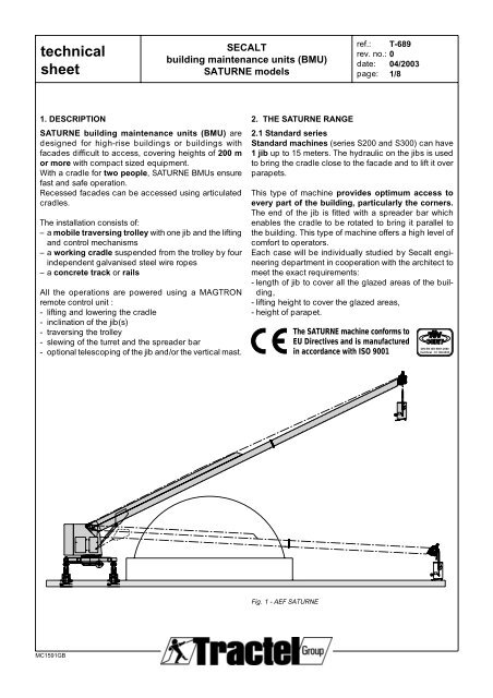
1. DESCRIPTION<br />
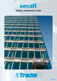
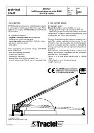
SATURNE building maintenance units (BMU) are<br />
designed for high-rise buildings or buildings with<br />
facades difficult to access, covering heights of 200 m<br />
or more with compact sized equipment.<br />
With a cradle for two people, SATURNE BMUs ensure<br />
fast and safe operation.<br />
Recessed facades can be accessed using articulated<br />
cradles.<br />
The installation consists of:<br />
–a mobile traversing trolley with one jib and the lifting<br />
and control mechanisms<br />
–a working cradle suspended from the trolley by four<br />
independent galvanised steel wire ropes<br />
–a concrete track or rails<br />
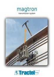
All the operations are powered using a MAGTRON<br />
remote control unit :<br />
- lifting and lowering the cradle<br />
- inclination of the jib(s)<br />
- traversing the trolley<br />
- slewing of the turret and the spreader bar<br />
- optional telescoping of the jib and/or the vertical mast.<br />
MC1591GB<br />
SECALT<br />
building maintenance units (BMU)<br />
SATURNE models<br />
Fig. 1 - AEF SATURNE<br />
ref.: T-689<br />
rev. no.: 0<br />
date: 04/2003<br />
page: 1/8<br />
2. THE SATURNE RANGE<br />
2.1 Standard series<br />
Standard machines (series S200 and S300) can have<br />
1 jib up to 15 meters. The hydraulic on the jibs is used<br />
to bring the cradle close to the facade and to lift it over<br />
parapets.<br />
This type of machine provides optimum access to<br />
every part of the building, particularly the corners.<br />
The end of the jib is fitted with a spreader bar which<br />
enables the cradle to be rotated to bring it parallel to<br />
the building. This type of machine offers a high level of<br />
comfort to operators.<br />
Each case will be individually studied by Secalt engineering<br />
department in cooperation with the architect to<br />
meet the exact requirements:<br />
- length of jib to cover all the glazed areas of the building,<br />
- lifting height to cover the glazed areas,<br />
- height of parapet.<br />
The SATURNE machine conforms to<br />
EU Directives and is manufactured<br />
in accordance with ISO 9001<br />
DIN EN ISO 9001:2000<br />
Certificat : 01 100 6535
<strong>technical</strong><br />
<strong>sheet</strong><br />
Sa515B<br />
Sa518B<br />
Sa618B<br />
Sa625B<br />
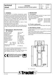
The above drawings show:<br />
- special machines Sa500 and Sa600 with their<br />
maximum range achieved to date.<br />
Max. suspended load : articulated cradle AC3 +<br />
working load limit + weight of wire ropes = ± 900 kg.<br />
3. IDENTIFICATION OF MACHINES<br />
MC1591GB<br />
SECALT<br />
building maintenance units (BMU)<br />
SATURNE models<br />
0 5 10<br />
15m<br />
Sa = SATURNE machine<br />
3 m cradle<br />
for 2 people<br />
5, 6 = single jib machine,<br />
with or without telescopic jib<br />
ref.: T-689<br />
rev. no.: 0<br />
date: 04/2003<br />
page: 2/8<br />
models Sa515/Sa518: single jib machines<br />
(fix or telescopic jib) with spreader bar<br />
and slewing ring. Optional increased jib<br />
height. Traversing on concrete track or<br />
rails. Jib length and working height*<br />
adapted to the configuration of the building.<br />
Weight ± 10000 kg.<br />
models Sa618/Sa625: single jib machines<br />
(fixed or telescopic jib) with spreader bar<br />
and slewing ring. Traversing on rails. Jib<br />
length and working height* adapted to<br />
the configuration of the building.<br />
Weight ± 18000 kg.<br />
* Above a lifting height of 40 meters, anchor plugs attached to the<br />
facade or continuous guides are necessary to limit the movement of<br />
the cradle caused by the wind. The cradle stops automatically at each<br />
anchor plug when being lowered or lifted (for details see <strong>technical</strong><br />
<strong>sheet</strong> T-517).<br />
Sa 5 15 A<br />
15 = fixing distance 1500 mm<br />
18 = fixing distance 1800 mm<br />
25 = fixing distance 2500 mm<br />
A = concrete track<br />
B = rails
<strong>technical</strong><br />
<strong>sheet</strong><br />
MC1591GB<br />
SECALT<br />
building maintenance units (BMU)<br />
SATURNE models<br />
4. STANDARD SATURNE MACHINES - SUMMARY TABLE<br />
ref.: T-689<br />
rev. no.: 0<br />
date: 04/2003<br />
page: 3/8<br />
maximum working height standard length of jibs track fixing distance<br />
model m m A B mm<br />
60 80 100 120 180 240 3 3,5 4 4,5 5 5,5 6 6,5 7 7,5 8 8,5 concr. rails 1500 1800<br />
Sa 515A P X X X X X X X<br />
P X X X X X X X X X X X X<br />
F X X X X X X X<br />
F X X X X X X X X X X X X<br />
Sa 515B P X X X X X X<br />
P X X X X X X X X X X X X<br />
F X X X X X X X<br />
F X X X X X X X X X X X X X<br />
Sa 518 B P X X X X X X X<br />
P X X X X X X X X X X<br />
F X X X X X X X<br />
F X X X X X X X X X X<br />
maximum working height standard length of jibs track fixing distance<br />
model m m A B mm<br />
60 80 100 120 180 240 5 6 7 8 9 10 11 12 13 14 15 16 concr. rails 1800 2500<br />
Sa 618B R X X X X X X X X X X X X<br />
Sa 618B T1 5/7 R X X X X X X X X X X X<br />
Sa 618B T1 6/9 R X X X X X X X X X X X X<br />
Sa 625B T1 8/12 R X X X X X X X X X X X X X<br />
Sa 625B T1 9/13 R X X X X X X X X X X X X X<br />
Sa 625B T1 10/14 R X X X X X X X X X X X X X<br />
Sa 625B T2 6/12 R X X X X X X X X X X X X X X X<br />
F = fixed spreader bar<br />
P = rotating spreader bar with parallelogram system<br />
R = rotating spreader bar<br />
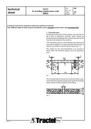
5. MAIN COMPONENTS OF A SPECIAL SATURNE MACHINE Sa515B and Sa625B (see figure 3)<br />
1. Turret<br />
2. Powered slewing ring<br />
3. Traversing trolley<br />
4. Jib<br />
5. Powered roller frame<br />
6. Geared motor with brake<br />
7. Rear roller frame (not powered)<br />
8. Guide wheel<br />
9. Reeler for power supply cable<br />
10. Guide for power supply cable<br />
11. Counterweight<br />
12. Hydraulic ram / connecting bar<br />
13. TWIN-TIRAK hoist with double wire rope reel<br />
14. Geared slewing motor<br />
15. Hydraulic unit<br />
16. Overload limit device<br />
18. Upper limit safety device<br />
19. FINAL upper limit safety device<br />
21. Suspension rope<br />
22. Cradle<br />
23. Support roller<br />
24. Anti-collision bar<br />
25. Swivel castor<br />
26. Cradle control box<br />
28. Side beam<br />
28.1 Side beam motor<br />
28.2 Spreader bar slewing ring<br />
28.3 Spreader bar arm
<strong>technical</strong><br />
<strong>sheet</strong><br />
28.2<br />
28<br />
28.1<br />
21<br />
16<br />
23<br />
2<br />
25 24<br />
3<br />
26<br />
28.3<br />
Fig. 3<br />
SATURNE BMU on rails<br />
MC1591GB<br />
22<br />
18/19<br />
4<br />
SECALT<br />
building maintenance units (BMU)<br />
SATURNE models<br />
12<br />
1<br />
5<br />
8<br />
6 9<br />
15<br />
14<br />
10<br />
7<br />
11<br />
13<br />
ref.: T-689<br />
rev. no.: 0<br />
date: 04/2003<br />
page: 4/8
<strong>technical</strong><br />
<strong>sheet</strong><br />
6. DESCRIPTION OF THE COMPONENTS<br />
6.1. Traversing trolley<br />
The lower trolley (3) is a tubular structure with hot dip<br />
galvanised protection.<br />
The trolley (3) and the turret (1) are connected by a<br />
powered slewing ring (2).<br />
For a SATURNE running on concrete trackway and with<br />
a 1500 mm turret, the rear wheels are mounted on an<br />
articulated spreader beam to ensure an even spread of<br />
the load on each of the four roller frames.<br />
6.2. Traversing system<br />
Traversing by electrical motor, speed 8 m/min.<br />
The trolley is fitted with 4 wheels with polyurethan tread<br />
giving smooth and silent traversing and a good grip.<br />
From the series Sa625 upwards these roller wheels are<br />
in steel. In general, only the 2 wheels on the facade are<br />
powered.<br />
The trolley is guided along the track by guide wheels<br />
(8) placed laterally on the roller frames, whether "L"<br />
shaped guide rails (Fig. 4), concrete guides or rails (Fig.<br />
5) are used.<br />
Fig. 4 - Traversing on concrete track,<br />
with "L" shaped guide rail<br />
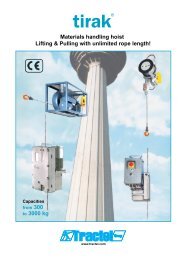
6.3. Lifting mechanism<br />
The lifting mechanism (13)<br />
consists of two TWIN-TIRAK<br />
model T-1000 hoists, manufactured<br />
by the TRACTEL Group<br />
and specially designed for<br />
SECALT building maintenance<br />
units. The wire rope travels in an<br />
"S" shaped path around the two<br />
adhesion pulleys (Fig. 6). The<br />
TWIN-TIRAK hoist is fitted with<br />
an overspeed safety brake<br />
which operates if the cradle descends<br />
too fast, and a disc brake,<br />
which is opened electrically as<br />
soon as the power is supplied<br />
to the motor.<br />
MC1591GB<br />
SECALT<br />
building maintenance units (BMU)<br />
SATURNE models<br />
Fig. 5 - Traversing on rails<br />
Fig. 6 - TIRAK<br />
lifting mechanism<br />
ref.: T-689<br />
rev. no.: 0<br />
date: 04/2003<br />
page: 5/8<br />
6.4. Hydraulic system<br />
– Depending upon the configuration of the machine,<br />
the hydraulic unit supplies :<br />
a) the motor for slewing the turret<br />
b) a ram which operates the extension/retraction of<br />
the telescopic jib or the inclination of the jib<br />
c) a ram which operates the extension/retraction of<br />
the telescopic mast (see 6.7).<br />
6.5. Jib(s)<br />
– SPECIAL series: The single jib can be fixe or telescopic<br />
(1 or 2 telescopic parts).<br />
6.6. Spreader bar<br />
The spreader bar on the special machines is fixed at<br />
the head of the jib. It enables the cradle to be rotated by<br />
of about 140°.<br />
6.7. Electrical circuit<br />
The electrical circuit consists of the following main items<br />
a) On the building (supplied by the customer)<br />
- the main switch, located on the roof<br />
- power supply points, 3-phase + earth, positioned along<br />
the track and protected by a 30 mA differential circuitbreaker<br />
b) On the trolley<br />
- the power supply cable for connecting the trolley to<br />
the power points. This cable is stored on a reeler (9)<br />
under the trolley.<br />
- an electrical box with a remote control for the trolley<br />
c) On the cradle<br />
- a MAGTRON control box<br />
- an auxiliary control box.
<strong>technical</strong><br />
<strong>sheet</strong><br />
6.8. Cradle<br />
The standard cradle (22) is a tubular aluminium structure,<br />
cladded in perforated aluminium panels.<br />
Length 3 m. Capacity 240 kg max.<br />
The special articulated cradle (Fig. 3.1) is suitable for<br />
facades recessed up to 3 m with regards to the suspension<br />
ropes (model AC3). There is also another, lighter,<br />
version for recesses up to 2 m (see <strong>technical</strong> <strong>sheet</strong> T-527).<br />
Two foam rollers (23) allow the cradle to rest lightly<br />
against the facade (max. effort 25 daN) and absorb the<br />
swinging movements of the cradle. Four swivel castors<br />
(25) fitted to the base of the cradle ease transport on<br />
the ground.<br />
An anti-collision bar (24) fitted under the cradle prevents<br />
collision with obstacles on lowering.<br />
6.9. Wire ropes<br />
The cradle is suspended from the jib by four steel wire<br />
ropes (21), Ø 8.3 mm, type E8 (5x26 + greased PP),<br />
minimum guaranteed breaking load 5150 daN. When<br />
the wire ropes have passed through the hoist they are<br />
wound on powered double reelers (13.1), driven by the<br />
output shaft of the hoist, via a chain and pinion system.<br />
MC1591GB<br />
spreader bar<br />
cradle<br />
traversing<br />
trolley<br />
SECALT<br />
building maintenance units (BMU)<br />
SATURNE models<br />
27<br />
16.1<br />
16.2<br />
16.3<br />
13.2<br />
16<br />
13.1<br />
13<br />
16.3<br />
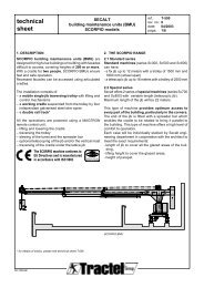
Fig. 7 - Diagrammatic representation of the wire ropes<br />
standard machine<br />
13 TWIN-TIRAK hoist 16.1 Overload safety device<br />
13.1 Wire rope reel 16.2 Insulated attachment<br />
13.2 Return pulley 16.3 MAGTRON link<br />
16 Slack wire rope safety device 21. Suspension wire rope<br />
27. Transducer<br />
Magnetic<br />
sensor<br />
Fig. 8<br />
Fault display<br />
Position<br />
switch<br />
Coding<br />
card<br />
Valve<br />
20-function<br />
trolley<br />
remote<br />
control<br />
ref.: T-689<br />
rev. no.: 0<br />
date: 04/2003<br />
page: 6/8<br />
7. ELECTRICAL EQUIPMENT<br />
In order to meet customers’ requirements during installation,<br />
reduce maintenance costs and improve the<br />
efficiency of operators, the design of our electrical<br />
equipment uses the most modern techniques :<br />
- programmable logic controller (PLC)<br />
- MAGTRON patented remote control system<br />
- microprocessor card, developed by SECALT for the<br />
remote control of the trolley<br />
- display units to assist with control and maintenance.<br />
7.1 Control circuit<br />
The equipment is controlled by a TELEMECANIQUE TSX<br />
37-10 programmable controller (PLC) with commands<br />
via :<br />
- 1 trolley remote control panel with a 20-function keypad<br />
- 1 cradle remote control panel with MAGTRON 4020<br />
The PLC performs three essential functions:<br />
a) Control of the various operating sequences<br />
b) Handling faults<br />
c) Decoding the trolley and cradle control signals.<br />
Transmission<br />
on 2 wires<br />
Contactor<br />
MAGTRON<br />
4020<br />
remote<br />
control<br />
Motor<br />
AUTOMATE / PLC<br />
MAGTRON<br />
CARD<br />
Transmission on<br />
RS485 serial link<br />
Trolley<br />
transducers<br />
Closed circuit<br />
Cradle<br />
transducers
<strong>technical</strong><br />
<strong>sheet</strong><br />
7.2 MAGTRON remote control<br />
The MAGTRON system is used for duplex transmission<br />
of data and telephone signals between the cradle and<br />
the trolley, by induction of the magnetic field in a closed<br />
circuit created by the steel carrying wire ropes (Fig.<br />
8). The signals are transmitted by 4 transducers (1<br />
transmission/1 reception on the cradle and on the trolley).<br />
7.2.1. Advantages of the MAGTRON system<br />
- transmission of commands via the standard metal<br />
suspension rope, removing the need for a pendant<br />
electrical cable or a special suspension cable with<br />
integrated electrical wires;<br />
- MAGTRON does not need a special frequency band;<br />
- as the transmission medium is the metal wire rope and<br />
not radio waves, MAGTRON is much less sensitive to<br />
interference created by other devices and does not<br />
itself cause interference to other systems (electronic<br />
or data processing systems, etc);<br />
- MAGTRON control is exclusively for our machines,<br />
whereas radio remote control systems are used by<br />
many other applications, with the possible risk of<br />
there being 2 radios of the same frequency on 2<br />
neighbouring sites;<br />
- control voltage reduced to 10 V, thus preventing any<br />
risk of electrocution;<br />
- the telephone and the display to assist with control<br />
are provided as standard;<br />
- one MAGTRON model covers our whole range of<br />
BMUs;<br />
- the MAGTRON cradle control box is easy to remove<br />
in order to protect it from adverse weather conditions<br />
and prevent improper use of the machine.<br />
The MAGTRON equipment has been the subject of a<br />
safety analysis (APAVE no. 9454079) [French organisation]<br />
which guarantees that a system failure will not cause<br />
a dangerous situation such as the loss of the emergency<br />
stop or the transmission of an incorrect command.<br />
7.3 Telephone and alarm system<br />
7.3.1 Trolley/cradle telephone<br />
The MAGTRON remote control is fitted with a telephone<br />
(106) for communication with the trolley telephone, using<br />
the principle of alternate transmission.<br />
7.3.2 Control office telephone (option)<br />
Telephone link between the cradle and the building’s<br />
control office (using the principle of alternate transmission).<br />
7.3.3 Control office alarm (option)<br />
In the event of a fault, an alarm (1 volt-free contact) is<br />
sent automatically to the control office or the <strong>technical</strong><br />
room.<br />
MC1591GB<br />
SECALT<br />
building maintenance units (BMU)<br />
SATURNE models<br />
ref.: T-689<br />
rev. no.: 0<br />
date: 04/2003<br />
page: 7/8<br />
7.4 Controls<br />
The equipment has two control panels :<br />
- 1 main control panel (112) on the cradle (Fig. 11)<br />
- 1 control panel (Fig. 9) on the trolley for switching to<br />
work phase and for backup operations in the event of<br />
failure of the main panel.<br />
The control panel is selected using the key switch (32)<br />
on the main control box.<br />
The electrical enclosure is fitted with a heater to prevent<br />
condensation.<br />
7.4.1 Main control box<br />
31. Main switch<br />
33<br />
34 32. Lockable rotary<br />
T1<br />
switch for<br />
T1<br />
F1 F3<br />
F2 F4<br />
TROLLEY control or<br />
CRADLE control<br />
33. PLC display<br />
106<br />
34. Trolley remote<br />
32 control<br />
31 43. Buzzer<br />
115<br />
106. Telephone<br />
43 115. Call cradle<br />
Fig. 9 - Main control box and trolley remote control<br />
7.4.2 MAGTRON remote control in the cradle (Fig. 11)<br />
113. MAGTRON control keypad (identical commands<br />
to those of the trolley remote control)<br />
104. Display<br />
106. Telephone<br />
114. Charger<br />
7.4.3 Cradle auxiliary control box (Fig. 10)<br />
42. Emergency stop<br />
102. Start/Stop MAGTRON<br />
103. Lower anti-collision bar shunt<br />
102<br />
42<br />
103<br />
104<br />
113<br />
112<br />
Fig. 10 - Cradle auxiliary control box Fig. 11 - Cradle control box<br />
7.5 Power supply to cradle MAGTRON control box<br />
The cradle assembly is supplied by a NI/MH (nickel<br />
hydride) main battery with a capacity of 9 hours.<br />
Recharging takes 3 hours.<br />
A NI/CD (nickel cadmium) back-up battery which<br />
provides one hours operation is brought into operation<br />
automatically when the main battery is flat so that the<br />
user can take the cradle back up to the roof.<br />
106<br />
114
<strong>technical</strong><br />
<strong>sheet</strong><br />
8. SAFETY DEVICES<br />
To ensure safe operation without danger to personnel,<br />
the machine is fitted with a number of safety<br />
devices which monitor the correct operation of the<br />
various components and operate in the event of a<br />
breakdown or fault.<br />
8.1. Safety devices on the cradle<br />
- emergency stop<br />
- lower anti-collision bar<br />
- overload safety device<br />
- cradle anti-tilt safety device<br />
8.1.1 Optional safety devices on the cradle<br />
- upper anti-collision bar<br />
8.2 Safety devices on the trolley<br />
- emergency stop<br />
- cradle upper safety limit switch<br />
- cradle FINAL upper safety limit switch<br />
- spreader bar slewing<br />
- slack wire rope safety device<br />
- end of wire rope safety device<br />
- electrical supply cable end limit switch<br />
- traversing end limit switch<br />
- turret slewing<br />
- overspeed<br />
- emergency lowering handle<br />
- phase order safety device<br />
- manual lowering in the event of a power break<br />
- telescopic jib retraction/extension<br />
8.2.1 Optional safety devices on the trolley<br />
- jib lifting safety device<br />
- jib anti-collision device<br />
- anemometer (wind speed indicator)<br />
- detector for presence of rail or concrete guide<br />
8.3 Self-test safety devices<br />
- on the MAGTRON<br />
- on the trolley remote control<br />
- on the contactors<br />
MC1591GB<br />
SECALT<br />
building maintenance units (BMU)<br />
SATURNE models<br />
9. FAULT MANAGEMENT<br />
ref.: T-689<br />
rev. no.: 0<br />
date: 04/2003<br />
page: 8/8<br />
9.1 Display on the PLC<br />
The faults listed below are handled by the TSX 37-10<br />
PLC and shown on the display (33).<br />
The display can also be temporarily assigned to the<br />
following maintenance functions :<br />
- display of the state of the PLC I/O<br />
- display of faults on the I/O cards<br />
- display of codes sent by the trolley or cradle remote<br />
controls<br />
CODES DEFAUTS - FAULT CODES<br />
Machine prête Mou de câble<br />
Machine ready Slack wire rope detector<br />
Arrêt d'urgence chariot Bimétal TIRAK<br />
Trolley emergency stop TIRAK heat sensor<br />
Arrêt d'urgence plate-forme Magnétiques moteurs<br />
Platform emergency stop Magnetic motor protection<br />
Arrêt d'urgence phonie chariot Défaut E/S automate<br />
Trolley phone emergency stop PLC system I/O fault<br />
Arrêt d'urgence phonie plate-forme Défaut RS485<br />
Platform phone emergency stop RS485 faulty<br />
Défaut test feedback Détecteur de rotation<br />
Feedback test faulty Slewing detector<br />
Défaut test entrées chariot Défaut contrôles télécommande<br />
Trolley inputs test faulty Pendant control card faulty<br />
Défaut test entrées plate-forme Défaut pile automate<br />
Platform inputs test faulty PLC battery fault<br />
Défaut test RS485 / Arrêt d'urgence Barre anticollision haute<br />
RS485 / Emergency stop test faulty Upper anti-collision bar<br />
Fin de course ultime haut Anticollision droit sur flèche<br />
Final upper limit switch Jib right anti-colllision<br />
Survitesse Anticollision gauche sur flèche<br />
Overspeed Jib left anti-collision<br />
Fin de câble Anémomètre<br />
End wire rope detector Wind speed indicator<br />
Contrôleur de phases<br />
Phase control<br />
Défaut contacteurs Demande de start<br />
Power relay faulty Start required<br />
Fin de course manivelle Manque fin de course haut<br />
Limit switch handle No upper limit switch<br />
Surcharge Manque sélection chariot ou plate-forme<br />
Overload No selection of trolley or cradle<br />
Barre anticollision basse<br />
Lower anti-collision bar<br />
Les défauts 2 et 23 restent mémorisés jusqu'au prochain start.<br />
The faults 2 and 23 are memorised until next start.<br />
9.2 Display in the cradle<br />
This display provides the operator with information on :<br />
- the battery capacity<br />
- the state of the sensors fitted on the cradle<br />
- the control fault codes.