technical sheet
technical sheet
technical sheet

You also want an ePaper? Increase the reach of your titles
YUMPU automatically turns print PDFs into web optimized ePapers that Google loves.
<strong>technical</strong><br />
<strong>sheet</strong><br />
MC1211<br />
tracks<br />
for building maintenance units<br />
(BMU)<br />
T-528<br />
2<br />
11/98<br />
1/11<br />
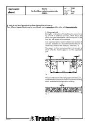
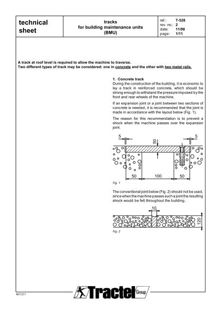
A track at roof level is required to allow the machine to traverse.<br />
Two different types of track may be considered: one in concrete and the other with two metal rails.<br />
1. Concrete track<br />
During the construction of the building, it is economic to<br />
lay a track in reinforced concrete, which should be<br />
strong enough to withstand the pressure imposed by the<br />
front and rear wheels of the machine.<br />
If an expansion joint or a joint between two sections of<br />
concrete is needed, it is recommended that the joint is<br />
made in accordance with the layout below (Fig. 1).<br />
The reason for this recommendation is to prevent a<br />
shock when the machine passes over the expansion<br />
joint.<br />
Fig. 1<br />
5 5<br />
50<br />
50<br />
100<br />
50<br />
The conventional joint below (Fig. 2) should not be used,<br />
since when the machine passes such a joint the resulting<br />
shock would be felt throughout the building.<br />
Fig. 2<br />
10<br />
ref.:<br />
rev. no.:<br />
date:<br />
page:<br />
120
<strong>technical</strong><br />
<strong>sheet</strong><br />
110<br />
100-<br />
140<br />
MC1211<br />
270<br />
2200<br />
10<br />
100<br />
20 20<br />
40<br />
30<br />
L 100x50x6<br />
DIN 1029<br />
HOLE TROU Ø 15<br />
PLAT FLAT 40x10 PLATE 40x10<br />
DIN 1017<br />
500 1300 400<br />
230<br />
tracks<br />
for building maintenance units<br />
(BMU)<br />
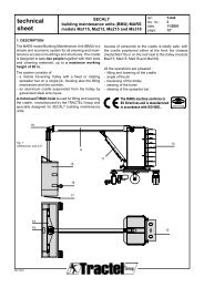
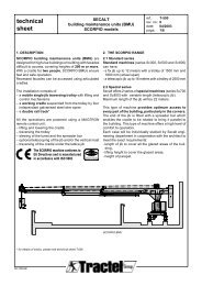
Fig. 3<br />
Concrete track with<br />
"L" shaped guide rail<br />
for JUNIOR 213A machine.<br />
ref.:<br />
rev. no.:<br />
date:<br />
page:<br />
T-528<br />
2<br />
11/98<br />
2/11<br />
1.1. Concrete track - with "L" shaped guide rail<br />
Angled metal guide rail fixed to the concrete.<br />
Hot galvanised for protection.<br />
The drawing below (Fig. 3) shows the track for a<br />
JUNIOR 213A machine:<br />
a) location and size of the trolley in relation to the track<br />
b) location of the track in relation to the parapet.<br />
concrete<br />
safety guide<br />
100x100<br />
concrete track<br />
weatherproofing<br />
insulation
<strong>technical</strong><br />
<strong>sheet</strong><br />
2200<br />
MC1211<br />
270<br />
230<br />
1700<br />
1530<br />
568<br />
330<br />
268<br />
930 1270<br />
concrete safety guide<br />
tracks<br />
for building maintenance units<br />
(BMU)<br />
R 1000<br />
268 979<br />
1530<br />
37°<br />
568<br />
330<br />
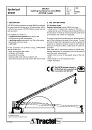
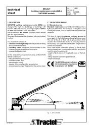
Fig. 4<br />
Example of layout<br />
of a concrete track<br />
with "L" shaped guide rail<br />
for JUNIOR 213A machine *<br />
R 1000<br />
R 700<br />
90°<br />
979<br />
268<br />
250<br />
1270 930<br />
R 1000<br />
37°<br />
164°<br />
R 3056<br />
100<br />
268<br />
*please consult SECALT<br />
for the other types of machine<br />
ref.:<br />
rev. no.:<br />
date:<br />
page:<br />
250<br />
T-528<br />
2<br />
11/98<br />
3/11<br />
2200<br />
1700 230 270
<strong>technical</strong><br />
<strong>sheet</strong><br />
110<br />
100-<br />
140<br />
MC1211<br />
100<br />
270<br />
500 1300 400<br />
230<br />
tracks<br />
for building maintenance units<br />
(BMU)<br />
2200<br />
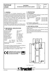
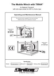
1.2. Concrete track - with concrete safety guide<br />
Fig. 5<br />
Concrete track with<br />
concrete guide for<br />
JUNIOR 213A machine.<br />
ref.:<br />
rev. no.:<br />
date:<br />
page:<br />
T-528<br />
2<br />
11/98<br />
4/11<br />
concrete<br />
safety guide<br />
100x100<br />
concrete track<br />
weatherproofing<br />
insulation
<strong>technical</strong><br />
<strong>sheet</strong><br />
2200<br />
MC1211<br />
270<br />
230<br />
1700<br />
1530<br />
568<br />
330<br />
268<br />
930 1270<br />
concrete safety guide<br />
tracks<br />
for building maintenance units<br />
(BMU)<br />
R 1000<br />
268 979<br />
1530<br />
37°<br />
568<br />
330<br />
Fig. 6<br />
Exampl of layout<br />
of a concrete track with<br />
concrete guide<br />
for JUNIOR 213A machine *<br />
R 1000<br />
R 700<br />
90°<br />
979<br />
268<br />
250<br />
1270 930<br />
R 1000<br />
37°<br />
164°<br />
R 3056<br />
100<br />
268<br />
*please consult SECALT<br />
for the other types of machine<br />
ref.:<br />
rev. no.:<br />
date:<br />
page:<br />
250<br />
T-528<br />
2<br />
11/98<br />
5/11<br />
2200<br />
1700 230 270
<strong>technical</strong><br />
<strong>sheet</strong><br />
Fig. 7<br />
Points for changing direction<br />
MC1211<br />
Curved<br />
rail section<br />
for change of<br />
direction<br />
straight rail section to be removed<br />
tracks<br />
for building maintenance units<br />
(BMU)<br />
ref.:<br />
rev. no.:<br />
date:<br />
page:<br />
T-528<br />
2<br />
11/98<br />
6/11<br />
1.3. Points for changing direction or parking<br />
In some cases the tracks on the roof must be fitted with<br />
points for :<br />
- the machine to change direction<br />
(in certain special cases)<br />
- parking the machine.<br />
The points consist in replacing a straight rail with a<br />
curved rail and vice versa so that the machine can<br />
change direction.<br />
The points are the same type as the guide rail on the<br />
roof, either an angled "L" rail, or concrete guide type.
<strong>technical</strong><br />
<strong>sheet</strong><br />
2. Metal track<br />
The rails are designed for fast and accurate assembly.<br />
The rail sections are joined together using bolted or<br />
welded fishplates. In open circuits, the last rail section<br />
must be attached using bolted fishplates.<br />
The rails and sleepers are hot galvanised to prevent<br />
corrosion. The size of the rail depends on the weight of<br />
the machine and the distance between the track support<br />
plinths.<br />
5 rail sizes are recommended (IPE160, IPE180, IPE200,<br />
HEA180, HEB200).<br />
The roller frames are defined by the type of BMU machine<br />
(Fig. 10, 11, 12, 13 and 14).<br />
MC1211<br />
tracks<br />
for building maintenance units<br />
(BMU)<br />
C<br />
A B<br />
6000<br />
5998<br />
Fig. 8<br />
Rail joint using<br />
2 bolted fishplates (A+B)<br />
= 2 flat plates 190x25x10 (IPE160) or<br />
230x30x10 (IPE180, IPE200,<br />
HEA180, HEB200)<br />
fishplate A<br />
with 4 countersunk holes<br />
fishplate B<br />
with 4 threaded holes M12<br />
2 1<br />
Fig. 9<br />
Rail joint using<br />
2 welded fishplates (A + B)<br />
= 2 flat plates 190x25x10 (IPE160) or<br />
230x30x10 (IPE180, IPE200,<br />
HEA180, HEB200)<br />
Bolt C:<br />
- For IPE and HEA<br />
Bolt M12x25<br />
DIN 7991 stainless steel<br />
- For HEB<br />
Bolt M12x30<br />
DIN 7991 stainless steel<br />
ref.:<br />
rev. no.:<br />
date:<br />
page:<br />
T-528<br />
2<br />
11/98<br />
7/11
<strong>technical</strong><br />
<strong>sheet</strong><br />
MC1211<br />
Fig. 10<br />
VENUS roller frame<br />
1000 daN<br />
on IPE 160 rail<br />
Fig. 13<br />
Roller frame 3800 daN<br />
on HEA 180 rail<br />
tracks<br />
for building maintenance units<br />
(BMU)<br />
Fig. 11<br />
Roller frame 2400 daN<br />
on IPE 180 rail<br />
ref.:<br />
rev. no.:<br />
date:<br />
page:<br />
Fig. 14<br />
Roller frame 4900 daN<br />
on HEB 200 rail<br />
T-528<br />
2<br />
11/98<br />
8/11<br />
Fig. 12<br />
Roller frame 2400 daN<br />
on IPE 200 rail
<strong>technical</strong><br />
<strong>sheet</strong><br />
rail<br />
sealing plate +<br />
packing<br />
cover<br />
reinforced concrete<br />
Fig. 15 - Concrete track support plinth<br />
rail<br />
sealing plate +<br />
packing<br />
cover<br />
reinforced concrete<br />
Fig. 16 - Concret plinth<br />
rail<br />
anchor flange<br />
sealing plate<br />
steel track<br />
support plinth<br />
MC1211<br />
M16 bolt<br />
separator<br />
cover<br />
reinforcing " I " type 125 Halfen M16<br />
type 50/30 bolt<br />
packing Halfen HTA 52/3 rail<br />
Fig. 17 - Potelet acier<br />
500<br />
500<br />
tracks<br />
for building maintenance units<br />
(BMU)<br />
anchor flange<br />
separator<br />
chemical plug<br />
type EPCON<br />
STIT M16<br />
anchor flange<br />
separator<br />
spacer<br />
M16 threaded rod<br />
The rails are supported on plinths every 2 or 3 m depending<br />
on the loading on the wheels of the machine.<br />
Three examples are given below:<br />
2.1. Concrete track support plinths (Fig. 15 & 16)<br />
A concrete track support plinth is made every 2 to 3 m<br />
to support the rail. The sleeper has a zinc cover and a<br />
seating plate which takes the adaptable rail fixing system.<br />
2.2. Steel track support plinths (Fig. 17)<br />
The steel track support plinth is a length of square hollow<br />
section to which a seating plate is soldered at one end.<br />
The adaptable rail fixing system is fitted to the seating<br />
plate.<br />
3000<br />
Fig. 18 - Position of seating plates<br />
ref.:<br />
rev. no.:<br />
date:<br />
page:<br />
6000<br />
T-528<br />
2<br />
11/98<br />
9/11<br />
2.3. Rail fixing system<br />
The concrete or steel track support plinths are fitted with<br />
an adaptable rail fixing system. This system has a<br />
separator placed under the rail with 2 or 4 anchor<br />
flanges.<br />
The separator has been specially designed to allow for<br />
flexing and expansion in the rail when it is fixed.<br />
It has three functions:<br />
- to spread the load on the seating plate<br />
- to absorbe the uneven contact between the rail and<br />
the seating plate<br />
- to reduce the noise and vibrations.<br />
The anchor flanges have been specially designed to<br />
meet the requirements of our machines, and in particular<br />
regarding the transverse adjustment and resistance to<br />
the lateral pressure applied by the guide rollers.<br />
The low height of the anchor flanges allows the travel of<br />
the horizontal guide rollers. Between the anchor flanges<br />
and the rail there is a block of synthetic elastomer. The<br />
anchor flanges are fixed to the seating plate by M16<br />
bolts, quality 8.8 and are galvanised for protection.
<strong>technical</strong><br />
<strong>sheet</strong><br />
7200 7200 7200<br />
MC1211<br />
butoir*<br />
Fig. 19 - Example of layout of track on rails<br />
5074<br />
buffer*<br />
tracks<br />
for building maintenance units<br />
(BMU)<br />
5124<br />
5998<br />
1300 500<br />
5998<br />
2944<br />
5998<br />
ref.:<br />
rev. no.:<br />
date:<br />
page:<br />
R700<br />
T-528<br />
2<br />
11/98<br />
10/11<br />
45°<br />
R2000<br />
*an end of track buffer<br />
must be used for<br />
"open" circuits<br />
45°
<strong>technical</strong><br />
<strong>sheet</strong><br />
100<br />
MC1211<br />
450<br />
190<br />
530<br />
Fig. 20<br />
Power point on concrte track support plinth<br />
gravel<br />
100<br />
weatherproofing<br />
thermic insulation<br />
stean shield<br />
concrete<br />
230<br />
500<br />
power point<br />
Fig. 21<br />
Power point on steel track support plinth<br />
110<br />
tracks<br />
for building maintenance units<br />
(BMU)<br />
300x300<br />
160<br />
100<br />
3. Power supply<br />
There should be power points every 40 m along the<br />
track (for JUNIOR and SENIOR machines) or every 30<br />
m for MINI machines.<br />
These power points may be fitted to the concrete (Fig.<br />
20) or steel sleepers (Fig. 21).<br />
chain link<br />
71<br />
tube 100x100x4<br />
150 70 120<br />
10 20<br />
ref.:<br />
rev. no.:<br />
date:<br />
page:<br />
HILTI HST M12/20-115 plug plate 10...200x200<br />
83<br />
T-528<br />
2<br />
11/98<br />
11/11<br />
130<br />
75<br />
Ø14<br />
100<br />
150<br />
200<br />
100<br />
790<br />
150<br />
200