Use of COMSOL In Aerodynamic Optimization of the ... - COMSOL.com
Use of COMSOL In Aerodynamic Optimization of the ... - COMSOL.com
Use of COMSOL In Aerodynamic Optimization of the ... - COMSOL.com

You also want an ePaper? Increase the reach of your titles
YUMPU automatically turns print PDFs into web optimized ePapers that Google loves.
Excerpt from <strong>the</strong> Proceedings <strong>of</strong> <strong>the</strong> <strong>COMSOL</strong> Conference 2008 Boston<br />
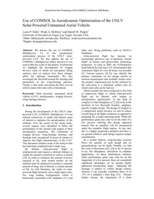
<strong>Use</strong> <strong>of</strong> <strong>COMSOL</strong> <strong>In</strong> <strong>Aerodynamic</strong> <strong>Optimization</strong> <strong>of</strong> <strong>the</strong> UNLV<br />
Solar-Powered Unmanned Aerial Vehicle<br />
Louis P. Dube 1 , Wade A. McElroy 2 and Darrell W. Pepper 3<br />
University <strong>of</strong> Nevada Las Vegas, Las Vegas, Nevada, USA<br />
1 Dube: ldube@unlv.nevada.edu, 2 McElroy: wade.mcelroy@charter.net,<br />
3 Pepper: dwpepper@nscee.edu<br />
Abstract: We discuss <strong>the</strong> use <strong>of</strong> <strong>COMSOL</strong><br />
Multiphysics 3.4 in <strong>the</strong> aerodynamic<br />
optimization process <strong>of</strong> <strong>the</strong> UNLV solarpowered<br />
UAV. We also address <strong>the</strong> use <strong>of</strong><br />
<strong>COMSOL</strong>’s Multiphysics ability and how it was<br />
used within <strong>the</strong> scope <strong>of</strong> <strong>the</strong> project. <strong>In</strong> particular<br />
we highlight <strong>the</strong> development <strong>of</strong> wingtip<br />
devices, some <strong>of</strong> which are non-planar lifting<br />
surfaces, and we analyze how <strong>the</strong>se changes<br />
affect <strong>the</strong> airframe structurally. We also<br />
investigate <strong>the</strong> flowfield around <strong>the</strong> fuselage and<br />
particularly at <strong>the</strong> wing-fuselage junction.<br />
Finally, a side study concerning <strong>the</strong> flow over an<br />
airfoil coated with solar cells is introduced.<br />
Keywords: Solar powered, unmanned aerial<br />
vehicle (UAV), aerodynamics, wingtip devices,<br />
wing-fuselage junction.<br />
1. <strong>In</strong>troduction<br />
During <strong>the</strong> development <strong>of</strong> <strong>the</strong> UNLV solarpowered<br />
UAV, <strong>COMSOL</strong> Multiphysics 3.4 was<br />
utilized extensively to model and analyze areas<br />
<strong>of</strong> interest to optimize <strong>the</strong> aerodynamics <strong>of</strong> <strong>the</strong><br />
airframe. Over <strong>the</strong> course <strong>of</strong> <strong>the</strong> sizing study,<br />
several regions were identified to better <strong>the</strong><br />
performance <strong>of</strong> <strong>the</strong> aircraft with respect to <strong>the</strong>ir<br />
aerodynamic properties. The refinement <strong>of</strong><br />
wingtip devices, wing-fuselage interface and<br />
fuselage were recognized as areas <strong>of</strong> interest to<br />
improve <strong>the</strong> flight characteristics <strong>of</strong> <strong>the</strong> UAV.<br />
This document outlines some <strong>of</strong> <strong>the</strong> analysis that<br />
has both been <strong>com</strong>pleted and is under way.<br />
By default, solar-powered flight is<br />
underpowered and requires a delicate balance to<br />
enable <strong>the</strong> aircraft to perform as well as it should<br />
[10]. <strong>In</strong> order to minimize <strong>the</strong> amount <strong>of</strong> power<br />
required to fly, each wetted surface on <strong>the</strong><br />
airplane must be optimized to produce a minimal<br />
amount <strong>of</strong> drag, and if desired, a certain amount<br />
<strong>of</strong> lift. As [10] illustrates, <strong>the</strong> realm <strong>of</strong> solarpowered<br />
flight primarily uses a high aspect ratio,<br />
low wing loading configuration, which is<br />
historically associated with sailplanes [11] and<br />
o<strong>the</strong>r slow flying platforms, such as NASA’s<br />
Pathfinder.<br />
Solar-powered flight has be<strong>com</strong>e an<br />
increasingly attractive way <strong>of</strong> attaining “eternal<br />
flight” as battery and photovoltaic technology<br />
progresses. As early as 2005, <strong>the</strong> ACPropulsion<br />
team behind <strong>the</strong> SoLong UAV demonstrated that<br />
continuous flight for over 48 hours was possible<br />
[1]. Various sources, [4] for one, identify <strong>the</strong><br />
primary constraints on <strong>the</strong> design criteria as<br />
mission requirements and available surface area:<br />
<strong>the</strong> primary requirement put on <strong>the</strong> airframe by<br />
<strong>the</strong> solar-array is a minimum surface area on<br />
which solar cells can be laid out.<br />
Much research has been conducted in <strong>the</strong> field<br />
<strong>of</strong> unpowered flight, to which solar-powered<br />
flight can be likened, with respect to<br />
aerodynamics optimization. <strong>In</strong> <strong>the</strong> field <strong>of</strong><br />
winglets we find Maughmer ([7], [8]) to be at <strong>the</strong><br />
forefront <strong>of</strong> low Reynolds Number, sailplanespecific<br />
winglet design. The design <strong>of</strong> winglets is<br />
a <strong>com</strong>plicated matter because we aim to reduce<br />
overall drag in all flight conditions as opposed to<br />
designing for a single operating point. While <strong>the</strong><br />
performance gains may only be on <strong>the</strong> order <strong>of</strong> a<br />
few percent, utilizing this design approach<br />
ensures that no penalties will be encountered<br />
under <strong>the</strong> <strong>com</strong>plete flight regime. At any rate,<br />
this is a highly proprietary problem and <strong>the</strong>re is<br />
no general solution: each design requires unique<br />
consideration.<br />
<strong>In</strong> a similar fashion, wing-fuselage junction<br />
flows are specific to each design and no<br />
generalizations can be made. Notably, we find<br />
<strong>the</strong> work <strong>of</strong> Boermans ([2], [3]) to be <strong>of</strong> interest<br />
as he, like Maughmer, specializes in sailplane<br />
applications. As <strong>the</strong>se publications mention,<br />
while performance gains may only be on <strong>the</strong><br />
magnitude <strong>of</strong> a few percent, <strong>the</strong>se are considered<br />
significant advantages on an already highly<br />
optimized aerodynamic shape. <strong>In</strong>herently <strong>the</strong><br />
fuselage is subject to similar design criteria,<br />
whereas it can typically contribute from 10 to<br />
15% <strong>of</strong> a sailplane’s total drag [13]. Thomas<br />
fur<strong>the</strong>r stresses <strong>the</strong> importance <strong>of</strong> a clean
aerodynamic shape, specifically in reference to<br />
<strong>the</strong> large wetted area associated with <strong>the</strong> fuselage<br />
and its consequent tapering around <strong>the</strong> wing root<br />
to lessen <strong>the</strong> adverse pressure gradients which<br />
may occur o<strong>the</strong>rwise.<br />
<strong>COMSOL</strong> was used to model <strong>the</strong> fluid flow<br />
around <strong>the</strong>se particular parts. As a follow-on<br />
study, structural parameters were input and <strong>the</strong><br />
mechanical behavior <strong>of</strong> <strong>the</strong> airframe <strong>the</strong>n<br />
observed simultaneously. Additionally, we<br />
explored <strong>the</strong> flow field around a twodimensional<br />
airfoil section and <strong>the</strong> effect <strong>of</strong> heat<br />
generation related to <strong>the</strong> solar cells.<br />
2. Problem Formulation<br />
The primary objective <strong>of</strong> winglets is to<br />
reduce overall drag. Originally, endplates were<br />
seen as a way to curb induced drag on real wings<br />
but it wasn’t until much later that winglets came<br />
into <strong>the</strong> form that we can all appreciate today on<br />
modern airliners [15]. There are various schools<br />
<strong>of</strong> thought in wingtip device design and some<br />
devices try to merge <strong>the</strong>se ideas. Planar devices<br />
usually try to ei<strong>the</strong>r capture <strong>the</strong> strength <strong>of</strong> <strong>the</strong><br />
trailing vortices or delay <strong>the</strong>ir creation fur<strong>the</strong>r<br />
outboard. Non-planar devices usually aim to do<br />
<strong>the</strong> same but tend to be more efficient since <strong>the</strong>y<br />
are out <strong>of</strong> <strong>the</strong> wing’s plane.<br />
Winglets have be<strong>com</strong>e an economical way <strong>of</strong><br />
retr<strong>of</strong>itting existing aircraft with a modification<br />
that lessens induced drag and thus reduces <strong>the</strong><br />
power requirements to fly at a particular<br />
airspeed. <strong>In</strong> <strong>the</strong> late 1980’s and early 1990’s,<br />
many would argue that winglets require too<br />
much design work to be effective, especially at<br />
slower speeds [11]. This was in part due to <strong>the</strong><br />
lack <strong>of</strong> <strong>com</strong>puting power and <strong>the</strong> difficulty<br />
involved in optimizing <strong>the</strong>se non-planar lifting<br />
surfaces for more than one flight condition.<br />
Similarly, a balance must be found between <strong>the</strong><br />
reduction in induced drag and <strong>the</strong> increase in<br />
parasitic drag that incurs with respect to <strong>the</strong> new<br />
wetted surfaces. For a fur<strong>the</strong>r discussion on<br />
induced and parasitic drag, please consult [6] and<br />
[14].<br />
Winglets conventionally have a set <strong>of</strong><br />
geometric parameters which can be modified to<br />
achieve desired performance. <strong>In</strong> addition to <strong>the</strong>se<br />
parameters, <strong>the</strong> airfoil used for a winglet will<br />
usually differ from <strong>the</strong> wing’s airfoil selection<br />
since it effectively is implemented for a different<br />
purpose. For a more detailed discussion on <strong>the</strong>se<br />
various parameters and how <strong>the</strong>y may affect <strong>the</strong><br />
results, refer to [8].<br />
The goal <strong>of</strong> this part <strong>of</strong> <strong>the</strong> study was to<br />
minimize <strong>the</strong> drag <strong>of</strong> <strong>the</strong> overall plane in all<br />
flight conditions. Due to <strong>the</strong> size restrictions put<br />
upon <strong>the</strong> project, <strong>the</strong> aspect ratio achieved was<br />
not nearly as high as o<strong>the</strong>r contemporary solar<br />
airplanes. To <strong>com</strong>bat this heightened induced<br />
drag factor and to better span efficiency, <strong>the</strong><br />
incorporation <strong>of</strong> winglets are studied and<br />
developed.<br />
Additionally, winglets usually increase wing<br />
bending moment, especially if <strong>the</strong>y result in a<br />
wingspan increase or if <strong>the</strong>y are non-planar<br />
lifting surfaces. As a result, a structural study<br />
had to be <strong>com</strong>pleted to ensure that <strong>the</strong> desired<br />
fabrication techniques and material selections<br />
were still appropriate.<br />
On an already highly optimized aerodynamic<br />
body, one <strong>of</strong> <strong>the</strong> major drag penalties arise from<br />
junction flow, categorized as interference drag<br />
[11]. Junction flows are highly proprietary in<br />
that <strong>the</strong>y cannot be generalized. Every situation<br />
is simply different, and while broad guidelines<br />
may be outlined, seldom will <strong>the</strong>y be <strong>the</strong><br />
<strong>com</strong>plete answer. For fur<strong>the</strong>r discussion on<br />
juncture flows and three-dimensional boundary<br />
layer interaction, see [12].<br />
Composites have made <strong>com</strong>plex,<br />
aerodynamically advantageous shapes a reality.<br />
As with winglets, increasing <strong>com</strong>puting power<br />
and more accurate fluid flow models have<br />
ramped up interest in <strong>the</strong> analysis and design <strong>of</strong><br />
wing-fuselage flow interaction. See [9] and [5],<br />
for example.<br />
The main objective <strong>of</strong> this part <strong>of</strong> <strong>the</strong> study<br />
was to minimize flow separation, which occurs<br />
at <strong>the</strong> junction and thus lessen <strong>the</strong> overall drag <strong>of</strong><br />
<strong>the</strong> plane. Additionally, <strong>the</strong> overall fuselage<br />
design was modeled to view <strong>the</strong> flow field and<br />
pressure distribution to ensure that laminar flow<br />
was preserved. One major design criterion <strong>of</strong> <strong>the</strong><br />
fuselage is to minimize and separate <strong>the</strong> adverse<br />
pressure gradients. Ano<strong>the</strong>r vital evaluation<br />
criterion is <strong>the</strong> interaction <strong>of</strong> <strong>the</strong> streamlines<br />
from <strong>the</strong> upper and lower halves <strong>of</strong> <strong>the</strong> fuselage,<br />
as well as <strong>the</strong> trailing edge <strong>of</strong> <strong>the</strong> wing. This<br />
evaluation is even fur<strong>the</strong>r <strong>com</strong>plicated, and<br />
generally dictated by, <strong>the</strong> taper <strong>of</strong> <strong>the</strong> fuselage<br />
around <strong>the</strong> airfoil section.<br />
Finally, a side study concerning <strong>the</strong> fluid flow<br />
over a solar-cell coated airfoil section is<br />
presented. <strong>In</strong> this on-going study, <strong>the</strong> flow field<br />
is analyzed for changes over <strong>the</strong> airfoil section as<br />
all three heat transfer modes are active. This<br />
model is currently being built up to accept a<br />
wider range <strong>of</strong> inputs, as discussed in <strong>the</strong> next<br />
section.
3. Models and Resources<br />
As most problems involved with fluid flow, a<br />
setup that would constitute a virtual wind tunnel<br />
was ideal. All <strong>of</strong> <strong>the</strong> three-dimensional problems<br />
could be divided along <strong>the</strong> longitudinal axis for<br />
symmetry. After <strong>the</strong> models were imported from<br />
<strong>the</strong> SolidWorks, a box was created which<br />
surrounded <strong>the</strong> whole <strong>of</strong> <strong>the</strong> model and gave<br />
sufficient room around <strong>the</strong> object to analyze <strong>the</strong><br />
flow, yet was tight enough to lower <strong>the</strong> number<br />
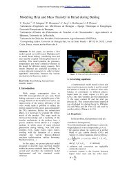
<strong>of</strong> internal nodes to a minimum. Figure 1<br />
illustrates such a configuration for a wingjunction<br />
flow study.<br />
Figure 1. Wing-junction flow model, isometric view.<br />
Typically, <strong>the</strong> fluid box was modeled to have<br />
one inlet and one outlet, three slip surfaces and<br />
one symmetry boundary, at <strong>the</strong> root <strong>of</strong> <strong>the</strong><br />
geometry being analyzed. The geometry itself<br />
consisted <strong>of</strong> non-slip interior boundaries. The<br />
box also provided easy boundary specifications<br />
for <strong>the</strong> structural problems. Additionally, this<br />
method allowed easy estimation <strong>of</strong> <strong>the</strong> drag<br />
forces produced by <strong>the</strong> various <strong>com</strong>ponents, if<br />
desired.<br />
Most models had around 170,000 elements,<br />
depending on <strong>the</strong> physical size <strong>of</strong> <strong>the</strong> object<br />
being studied and <strong>the</strong> accuracy desired. A mesh<br />
this size yielded about 580,000 degrees <strong>of</strong><br />
freedom, on average, for a single physics<br />
problem.<br />
<strong>COMSOL</strong>’s built-in fluid dynamics package<br />
uses <strong>the</strong> Navier-Stokes equations, as shown in<br />
(1) and (2).<br />
<strong>COMSOL</strong>’s ability to converge, but for <strong>the</strong> flow<br />
analysis <strong>the</strong> Vanka algorithm worked well.<br />
Additionally, <strong>COMSOL</strong>’s adaptive solver was<br />
used in conjunction with <strong>the</strong>se settings with good<br />
results. Some issues related to <strong>the</strong>se choices will<br />
be discussed later.<br />
For <strong>the</strong> structural analysis, <strong>the</strong> multiphysics<br />
aspect <strong>of</strong> <strong>the</strong> problem and <strong>the</strong> desire to<br />
simultaneously solve <strong>the</strong> fluid and structure<br />
problem proved demanding, but <strong>COMSOL</strong>’s<br />
fluid-structure interaction module handled <strong>the</strong>se<br />
problems properly and efficiently with <strong>the</strong><br />
default segregated solver settings, with minor<br />
modifications to <strong>the</strong> geometric multigrid solver.<br />
The fluid-structure module employs <strong>the</strong><br />
previously mentioned Navier Stokes equations<br />
coupled with a solid stress-strain physics module<br />
and a moving mesh module (ALE method).<br />
<strong>COMSOL</strong>’s free mesh utility had trouble dealing<br />
with some <strong>of</strong> <strong>the</strong> structure’s areas with more<br />
curvature and an automatic mesh hierarchy could<br />
not be readily achieved. This was resolved by<br />
building specific mesh cases but <strong>com</strong>puting<br />
times were found to be quite sluggish for some<br />
<strong>of</strong> <strong>the</strong> geometries.<br />
For <strong>the</strong> two-dimensional multiphysics<br />
problem involving flow and heat transfer, a<br />
similar arrangement to <strong>the</strong> three-dimensional<br />
problems was used with a fluid box being built<br />
around <strong>the</strong> airfoil. The fluid-<strong>the</strong>rmal module was<br />
used for this problem. For <strong>the</strong> fluid sub-problem,<br />
<strong>the</strong>re is one inlet, one outlet and two slip<br />
surfaces, with <strong>the</strong> airfoil’s surface set as a nonslip<br />
interior boundary. The Weakly<br />
Compressible Navier Stokes mode was<br />
employed since <strong>the</strong> fluid’s density is expected to<br />
change, although slightly, with pressure and<br />
temperature. For <strong>the</strong> heat transfer, <strong>the</strong> boundaries<br />
were slightly more <strong>com</strong>plicated. Figure 2<br />
illustrates <strong>the</strong> problem configuration.<br />
u = V ∞ , T = T ∞<br />
<br />
· (1)<br />
<br />
·· (2)<br />
Various solvers were used for <strong>the</strong> fluid flow<br />
problems but generally speaking GMRES and<br />
FGMRES gave <strong>the</strong> best results when paired with<br />
Geometric Multigrid preconditioning. The preand<br />
postsmoo<strong>the</strong>rs played a large role in<br />
u = V ∞ , T = T ∞<br />
u = V ∞ , T = T ∞ p = 0, T = T ∞<br />
Figure 2. Boundary layout, heat generation module.
The airfoil’s top surface, highlighted in green<br />
in Figure 2, is considered a heat source to mimic<br />
an embedded thin-film solar panel. This surface<br />
also produces radiation that is both surface-toambient<br />
and surface-to-surface. The conduction<br />
through <strong>the</strong> panel itself is ignored since it is 60<br />
microns thick. The energy emanating from <strong>the</strong><br />
panel can be described as a function <strong>of</strong> its<br />
efficiency and <strong>the</strong> solar flux, as in equation (3),<br />
where denotes <strong>the</strong> heat generated, is <strong>the</strong><br />
solar panel efficiency and is <strong>the</strong> solar intensity,<br />
in units <strong>of</strong> W/m 2 .<br />
1 (3)<br />
The panel section <strong>of</strong> <strong>the</strong> airfoil can be<br />
formulated as a heat generator. Additionally, η<br />
varies with temperature , in degrees Kelvin, as<br />
described by equation (4). This equation was<br />
determined by ga<strong>the</strong>ring empirical data from<br />
solar cells used in a past iteration <strong>of</strong> <strong>the</strong> UAV<br />
project. The model could be made to consider a<br />
variety <strong>of</strong> solar panels but this not within <strong>the</strong><br />
scope <strong>of</strong> this study. The final term in <strong>the</strong><br />
equation represents peak cell efficiency. For<br />
example, <strong>the</strong>se particular cells have a maximum<br />
efficiency <strong>of</strong> 5% while more efficient cells may<br />
run as high as 10 to 15%.<br />
. <br />
0.05 (4)<br />
The bottom surface <strong>of</strong> <strong>the</strong> airfoil, which can<br />
be viewed as <strong>the</strong> remainder <strong>of</strong> <strong>the</strong> airfoil<br />
boundary in black on Figure 2, is modeled as<br />
continuity, or equation (5). The edges <strong>of</strong> <strong>the</strong> fluid<br />
box, <strong>the</strong> box around <strong>the</strong> airfoil, have temperature<br />
boundaries, as prescribed by equation (6). This<br />
simulates an ambient temperature envelope.<br />
∑ Δ (5)<br />
(6)<br />
The temperature <strong>of</strong> <strong>the</strong> airfoil core starts at an<br />
initial temperature which matches <strong>the</strong> subdomain’s<br />
initial temperature. With <strong>the</strong> model<br />
generated in such a way, solar radiation is<br />
assumed to be constant. The model could be<br />
built to fur<strong>the</strong>r consider additional variables.<br />
A dedicated machine was built to solve <strong>the</strong>se<br />
problems. Using previous experience with <strong>the</strong><br />
<strong>COMSOL</strong> engine, requirements for a simulation<br />
workstation were put toge<strong>the</strong>r. An abbreviated<br />
<strong>com</strong>ponents list can be viewed in Table 1. The<br />
final cost, as <strong>of</strong> August 2008, was around $1,300<br />
USD. Table 2 outlines some <strong>of</strong> <strong>the</strong> results used<br />
to benchmark <strong>the</strong> machine’s speed and stability.<br />
4. Results<br />
<strong>COMSOL</strong>’s output capabilities allowed us to<br />
easily and quickly analyze <strong>the</strong> results from<br />
simulations and ga<strong>the</strong>r a tremendous amount <strong>of</strong><br />
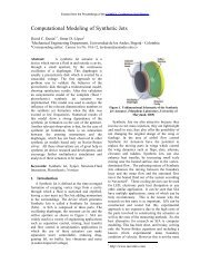
information simply by inspection. Figure 3<br />
shows how isosurface plots <strong>of</strong> <strong>the</strong> flow over <strong>the</strong><br />
fuselage were used to determine where and how<br />
pressure gradients occurred, and how to move<br />
through <strong>the</strong> design iterations to properly<br />
optimize <strong>the</strong> shape.<br />
While <strong>the</strong> primary function <strong>of</strong> <strong>the</strong> fuselage is<br />
to carry avionics and payload, <strong>the</strong> adverse<br />
pressure gradients near <strong>the</strong> wing must be<br />
minimized to reduce drag and special thought<br />
Table 1: Workstation <strong>com</strong>ponents list.<br />
CPU<br />
RAM<br />
Chipset<br />
Video<br />
OS<br />
<strong>In</strong>tel Q9450 Quad Core, rated at 2.66GHz per core, operating at 3.2GHz per core<br />
PC8500 RAM, 8GB, tightened timings 3-3-3-14, operating at 866MHz<br />
<strong>In</strong>tel P43<br />
Nvidia 9600GT<br />
Micros<strong>of</strong>t Vista Enterprise 64-bit<br />
Table 2: Workstation benchmarking; free bi/tri-linear mesh; GMRES, Geometric Multigrid except 04 (PARDISO).<br />
Benchmark<br />
Model Name<br />
Analysis Type<br />
Number <strong>of</strong><br />
Elements<br />
Number <strong>of</strong> Degrees<br />
<strong>of</strong> Freedom<br />
Time to Solution<br />
(seconds)<br />
01 Fluid, Steady State, 3D 56,780 261,567 1209.12<br />
02 Fluid, Steady State, 3D 157,570 651,248 3345.67<br />
03 Fluid, Steady State, Adaptive, 3D 9361/31096 45043/140756 8584.35<br />
04 Fluid-Thermal <strong>In</strong>teraction, 2D 3433 21191 37.64<br />
05 Fluid-Structure <strong>In</strong>teraction, 3D 4078 37299 377.03
vorticity streamline fields and boundary velocity<br />
plots, among o<strong>the</strong>rs. Figure 6 <strong>com</strong>pares pressure<br />
and flow behavior over <strong>the</strong> original wing and one<br />
<strong>of</strong> <strong>the</strong> winglet design iterations.<br />
Figure 3. Isosurface plot <strong>of</strong> <strong>the</strong> pressure distribution<br />
(lb f /ft 2 ) around <strong>the</strong> fuselage.<br />
must be put into its shaping. A secondary<br />
objective is to keep <strong>the</strong> flow laminar over <strong>the</strong><br />
body <strong>of</strong> <strong>the</strong> plane for as long as possible and to<br />
prevent separation in areas with <strong>com</strong>plex<br />
boundary layer interaction; for example, at <strong>the</strong><br />
wing-fuselage junction. Figure 4 shows a closeup<br />
<strong>of</strong> such a junction flow study. According to<br />
[9], only 20% <strong>of</strong> <strong>the</strong> wingspan from <strong>the</strong> root<br />
need be included to obtain valid results.<br />
Figure 5. Typical <strong>COMSOL</strong> output for winglet study:<br />
isosurface pressure distribution (lb f /ft 2 ) and velocity<br />
streamlines.<br />
Figure 4. Fluid flow at <strong>the</strong> wing-fuselage junction,<br />
with surface pressure (lb f /ft 2 ) and velocity streamlines.<br />
The winglet design study has so far shown an<br />
overall drag reduction <strong>of</strong> 8.1% at cruise<br />
condition over <strong>the</strong> original wing design, with<br />
smaller reductions in o<strong>the</strong>r flight conditions,<br />
such as turning flight or landing approach.<br />
Superimposition <strong>of</strong> <strong>the</strong> ga<strong>the</strong>red data from<br />
<strong>COMSOL</strong> onto <strong>the</strong> UAV’s flight polars shows<br />
no performance penalties. Figure 5 outlines <strong>the</strong><br />
typically sought information from <strong>COMSOL</strong>,<br />
such as isosurface pressure plotting, velocity and<br />
Figure 6. Flow field <strong>com</strong>parison between original<br />
wing and winglet design (top and bottom). Depicted:<br />
boundary plots representing surface pressure<br />
(lb f /ft 2 ) and velocity streamlines.<br />
<strong>COMSOL</strong>’s boundary integration mode is<br />
especially powerful when coupled with <strong>the</strong> weak
constraint variables. The boundary integration<br />
mode itself allows us to quickly find changes in<br />
overall drag. The weak constraint variables <strong>of</strong>fer<br />
an easy way <strong>of</strong> <strong>com</strong>puting <strong>the</strong> coefficients <strong>of</strong><br />
drag and lift, if desired. This feature was used in<br />
numerous instances during <strong>the</strong> fluid flow<br />
analysis, both as a way to benchmark <strong>the</strong><br />
accuracy <strong>of</strong> <strong>the</strong> models against known values and<br />
<strong>the</strong> obtained results against predicted data using<br />
various panel methods.<br />
The fluid-structure analysis allowed us to<br />
dynamically observe <strong>the</strong> effect <strong>of</strong> <strong>the</strong><br />
incorporation <strong>of</strong> winglets on <strong>the</strong> airframe, both<br />
from an aerodynamics and structural point-<strong>of</strong>view.<br />
The results could be numerically <strong>com</strong>pared<br />
to <strong>the</strong> original cases and direct considerations<br />
regarding <strong>the</strong> manufacturing <strong>of</strong> <strong>the</strong> airframe<br />
could be <strong>com</strong>pleted on <strong>the</strong> fly. For example,<br />
using one <strong>of</strong> <strong>the</strong> evaluated building materials,<br />
polystyrene, <strong>the</strong> original wing showed a<br />
deflection <strong>of</strong> 0.0004” at <strong>the</strong> tip, as <strong>com</strong>pared to a<br />
0.007” tip deflection with a winglet device.<br />
Figure 7 shows typical output in close-up.<br />
The fluid-<strong>the</strong>rmal analysis on <strong>the</strong> twodimensional<br />
airfoil section is still on-going but<br />
preliminary results have been obtained and <strong>the</strong><br />
study is being pushed ahead toward more<br />
ambitious concepts. So far, <strong>COMSOL</strong>’s<br />
multiphysics abilities have been used to observe<br />
<strong>the</strong> effect <strong>of</strong> heat generation on <strong>the</strong> flow and its<br />
propagation through <strong>the</strong> wing core, through a<br />
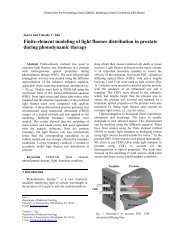
simplified model as described earlier. Figure 9<br />
shows a surface plot <strong>of</strong> <strong>the</strong> temperature pr<strong>of</strong>ile<br />
around and in <strong>the</strong> airfoil section, coupled with a<br />
streamline plot.<br />
Figure 8. Full airframe fluid analysis with boundary<br />
plot showing surface pressure (lb f /ft 2 ) and velocity<br />
streamlines for flow analysis.<br />
These plots revealed some interesting<br />
information which was not expected at <strong>the</strong> onset<br />
<strong>of</strong> <strong>the</strong> study. For example, <strong>the</strong> maximum service<br />
temperature <strong>of</strong> some <strong>of</strong> <strong>the</strong> building materials in<br />
<strong>the</strong> wing core were quite low and it was found<br />
that this temperature could be exceeded in some<br />
cases.<br />
Figure 7. Boundary plot showing wing total<br />
displacement (in) with velocity streamlines.<br />
Additional data regarding <strong>the</strong> <strong>com</strong>plete<br />
airframe was ga<strong>the</strong>red by studying <strong>the</strong> flow field<br />
around <strong>the</strong> <strong>com</strong>plete structure. Such simulations<br />
enabled a direct correlation between estimated<br />
flight polars from <strong>the</strong> original sizing study and<br />
<strong>COMSOL</strong>’s numerically evaluated aerodynamic<br />
values, such as <strong>the</strong> various lift and drag<br />
coefficients earlier discussed. <strong>In</strong> general, <strong>the</strong> data<br />
agreed well. Additionally, estimated values from<br />
<strong>the</strong> sizing study, such as overall zero-lift drag<br />
coefficient, could now be validated numerically<br />
and flight performance could be assessed at a<br />
deeper level. Figure 8 shows one such<br />
simulation’s output.<br />
Figure 9. Heat propagation in <strong>the</strong> flow field (surface<br />
plot, ºF) plotted with velocity streamlines (m/s).
5. Conclusion<br />
<strong>COMSOL</strong> Multiphysics 3.4 proved to be a<br />
valuable tool in <strong>the</strong> development <strong>of</strong> <strong>the</strong> UNLV<br />
solar-powered UAV. <strong>In</strong> overview, we have<br />
demonstrated that this s<strong>of</strong>tware package can be<br />
used for small-scale evaluation <strong>of</strong> flying<br />
platforms, such as UAVs, and that <strong>the</strong><br />
multiphysics package provides an all-inclusive<br />
way to approach a design problem and quickly<br />
<strong>com</strong>e up with a development solution.<br />
<strong>COMSOL</strong> provided results in a timely<br />
manner and allowed <strong>the</strong> designers <strong>of</strong> <strong>the</strong> UAV to<br />
optimize key parts <strong>of</strong> <strong>the</strong> airframe, primarily<br />
from an aerodynamics standpoint, but also to<br />
observe <strong>the</strong> structural side effects <strong>of</strong> <strong>the</strong>se<br />
modifications. The ability to simulate various<br />
flight conditions using single or multiple physics<br />
enabled <strong>the</strong> iterative design process and<br />
facilitated <strong>the</strong> development <strong>of</strong> <strong>the</strong> design into a<br />
(numerically) ready airframe. The fluid and<br />
structure modules were effective but <strong>COMSOL</strong>’s<br />
mesher had difficulties with <strong>the</strong> <strong>com</strong>plex<br />
curvature <strong>of</strong> <strong>the</strong> airfoil pr<strong>of</strong>ile and its subsequent<br />
extrusion along <strong>the</strong> wing’s span. This issue may<br />
have also resided partially with <strong>the</strong> CAD import<br />
module. These two issues resulted in dramatic<br />
increases in preparation time for some <strong>of</strong> <strong>the</strong><br />
simulations.<br />
Additionally, it was shown that <strong>COMSOL</strong><br />
can be run on a high-end desktop personal<br />
<strong>com</strong>puting machine to provide accurate results in<br />
respectable <strong>com</strong>puting times for fairly <strong>com</strong>plex<br />
problems. It was found on this machine that,<br />
using <strong>the</strong> GMRES solver, meshes with up to two<br />
million degrees <strong>of</strong> freedom could be solved<br />
before running out <strong>of</strong> memory.<br />
6. References<br />
[1] AC Propulsion. (2006, February 2).<br />
Technology - SoLong UAV. Retrieved<br />
August 10, 2007, from<br />
http://www.acpropulsion.<strong>com</strong>/solong/<br />
[2] Boermans, L. (2006). Research on sailplane<br />
aerodynamics at Delft University <strong>of</strong><br />
Technology. Recent and present<br />
developments. Presentation, Delft University<br />
<strong>of</strong> Technology, Delft.<br />
[3] Boermans, L., Kubrynski, K., & Nicolosi, F.<br />
(1997). Wing-Fuselage Design <strong>of</strong> High-<br />
Performance Sailplanes. <strong>In</strong> R. Henkes, & P.<br />
Bakker (Ed.), Boundary-Layer Separation in<br />
Aircraft <strong>Aerodynamic</strong>s (pp. 23-41). Delft:<br />
Delft University Press.<br />
[4] Brandt, S. A., & Gilliam, F. T. (1995).<br />
Design Analysis Methodology for Solar-<br />
Powered Aircraft. Journal <strong>of</strong> Aircraft , 32<br />
(4), 703-709.<br />
[5] Green, B. E., & Whitesides, J. L. (2003,<br />
March-April). Method for Designing<br />
Leading-Edge Fillets to Eliminate Flow<br />
Separation. Journal <strong>of</strong> Aircraft , 40 (2), pp.<br />
282-289.<br />
[6] Kue<strong>the</strong>, A. M., & Chow, C.-Y. (1986).<br />
Foundations <strong>of</strong> <strong>Aerodynamic</strong>s (Fourth<br />
Edition ed.). New York: John Wiley & Sons.<br />
[7] Maughmer, M. D. (2002, June). About<br />
Winglets. Soaring Magazine .<br />
[8] Maughmer, M. D. (2003). Design <strong>of</strong><br />
Winglets for High-Performance Sailplanes.<br />
Journal <strong>of</strong> Aircraft , 40 (6), 1099-1106<br />
[9] Maughmer, M., Hallman, D., Ruszkowski,<br />
R., Chappel, G., & Waitz, I. (1989, August).<br />
Experimental <strong>In</strong>vestigation <strong>of</strong><br />
Wing/Fuselage <strong>In</strong>tegration Geometries.<br />
Journal <strong>of</strong> Aircraft , 26 (8), pp. 705-711.<br />
[10] Noth, A. (2008). History <strong>of</strong> Solar flight.<br />
Electronic Report, Swiss Federal <strong>In</strong>stitute <strong>of</strong><br />
Technology Zürich, Autonomous Systems<br />
Lab, Zürich.<br />
[11] Raymer, D. P. (1999). Aircraft Design: A<br />
Conceptual Approach (Third Edition ed.).<br />
Reston, Virginia, United States <strong>of</strong> America:<br />
American <strong>In</strong>stitute <strong>of</strong> Aeronautics and<br />
Astronautics, <strong>In</strong>c.<br />
[12] Schlichting, H., & Gersten, K. (1999).<br />
Boundary Layer Theory (8th Revised and<br />
Enlarged Edition ed.). (K. Mayes, Trans.)<br />
New York: Springer.<br />
[13] Thomas, F. (1999). Fundamentals <strong>of</strong><br />
Sailplane Design. (J. Milgram, Trans.)<br />
College Park, Maryland: College Park Press.<br />
[14] Thwaites, B. (1960). <strong>In</strong><strong>com</strong>pressible<br />
<strong>Aerodynamic</strong>s. New York: Oxford<br />
University Press.<br />
[15] Whit<strong>com</strong>b, R. T. (1976). A Design<br />
Approach and Selected Wind-Tunnel Results<br />
at High Subsonic Speeds for Wing-Tip<br />
Mounted Winglets. NASA, Langley<br />
Research Center. Hampton: NASA.