This ring tester is an inexpensive and effective ... - Main Electronics
This ring tester is an inexpensive and effective ... - Main Electronics
This ring tester is an inexpensive and effective ... - Main Electronics

Create successful ePaper yourself
Turn your PDF publications into a flip-book with our unique Google optimized e-Paper software.
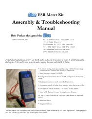
<strong>Th<strong>is</strong></strong> <strong>ring</strong> <strong>tester</strong> <strong>is</strong> <strong>an</strong> <strong>inexpensive</strong> <strong>an</strong>d <strong>effective</strong><br />
way to test <strong>an</strong>y high Q inductive component. It<br />
<strong>is</strong> especially useful for doing a quick check on<br />
flyback, line output tr<strong>an</strong>sformers <strong>an</strong>d other high<br />
frequency wound components like deflection<br />
yoke windings <strong>an</strong>d SMPS tr<strong>an</strong>sformers.<br />
The LEDs on the left side show the Q of the<br />
device being tested, more lights = higher Q, i. e.,<br />
no lights = short circuit, red = Bad or low Q,<br />
yellow = ??? or medium Q, green = Good or<br />
high Q.<br />
<strong>Th<strong>is</strong></strong> document was written by Bob Parker <strong>an</strong>d edited by John Bachm<strong>an</strong> at AnaTek Corporation. Some graphics<br />
<strong>an</strong>d text courtesy of Silicon Chip March/April <strong>is</strong>sue 2004.
Parts L<strong>is</strong>t<br />
Res<strong>is</strong>tors all 5% ¼ Watt Capacitors all 16<br />
WV minimum<br />
270 Ω, R15<br />
Red-Blue-Brown<br />
510 Ω, R7<br />
Green-Brown-Brown<br />
2.2 KΩ, R10, R16, R17, R18,<br />
R21, R22, R23<br />
Red-Red-Red<br />
4.7KΩ, R8, R19, R20<br />
Yellow-Violet-Red<br />
10 KΩ, R4, R14<br />
Brown-Black-Or<strong>an</strong>ge<br />
22 KΩ, R3<br />
Red-Red-Or<strong>an</strong>ge<br />
Semiconductors<br />
M<strong>is</strong>cell<strong>an</strong>eous<br />
1 nf ceramic, C3, C8 1N4148, D1, D2, D3 Pushbutton switch<br />
with cap<br />
100 nf ceramic, C1,<br />
C4, C5, C6 C7, C9<br />
2N3904, Q1, Q2, Q3 Blue Hammond<br />
enclosure<br />
10 uf electrolytic, C2 CD4069, IC1 Label<br />
CD4015, 1C2<br />
Red LED, LED1,<br />
LED2, LED3<br />
Yellow LED, LED4,<br />
LED5<br />
470 KΩ, R9, R13 Green LED, LED6,<br />
LED7, LED8<br />
1 MΩ, R1, R2, R5, R6, R11,<br />
R12<br />
Brown-Black-Green<br />
Pair of test leads<br />
Pair of alligator clips<br />
with insulators<br />
3” tie wrap<br />
2 grommets<br />
printed circuit board<br />
ferrite core <strong>an</strong>d wire<br />
LED
Construction<br />
As you c<strong>an</strong> see in the photos, all the components are mounted on a single PC board which <strong>is</strong> then attached to the<br />
enclosure bottom.<br />
Even though the pc board <strong>is</strong> high-quality with solder-mask it <strong>is</strong> still w<strong>is</strong>e to check it for defects. To do th<strong>is</strong>,<br />
illuminate the component side with a bright light <strong>an</strong>d examine the copper side very carefully – preferably with a<br />
magnifier – for <strong>an</strong>y hairline fractures in the tracks.<br />
Du<strong>ring</strong> assembly frequently check for <strong>an</strong>y solder “wh<strong>is</strong>kers” or bridges <strong>an</strong>d pay particular attention to <strong>an</strong>y tracks,<br />
which pass between IC pads, where such defects tend to congregate <strong>an</strong>d hide. It <strong>is</strong> good practice to install 5 or 6<br />
components <strong>an</strong>d then check the solde<strong>ring</strong> of them under a magnifier. Then move on <strong>an</strong>d install 5 or 6 more.<br />
The PC board <strong>is</strong> tightly packed <strong>an</strong>d the solder pads are quite small so be very careful with your solde<strong>ring</strong>. Always<br />
lift the iron vertically from a just soldered joint <strong>an</strong>d never wipe it sideways as so m<strong>an</strong>y constructors seem to do!<br />
Component Installation Sequence<br />
The kit package contains five plastic bags of components. Install them in the following order:<br />
5% res<strong>is</strong>tors<br />
Capacitors<br />
Semiconductors (See detailed description of LED installation)<br />
M<strong>is</strong>cell<strong>an</strong>eous parts<br />
The bag labeled “test” contains <strong>an</strong> inductor that will use after your unit <strong>is</strong> assembled. The inductor <strong>is</strong> not installed<br />
on the pc board.<br />
NOTE: A late design ch<strong>an</strong>ge made R7 510 ohms (green-brown-brown) instead of the 2.2 Kohms shown<br />
on the pcb silkscreen. <strong>Th<strong>is</strong></strong> ch<strong>an</strong>ge makes the <strong>tester</strong> more sensitive when used on low imped<strong>an</strong>ce<br />
components such as SMPS tr<strong>an</strong>sformers <strong>an</strong>d deflection yoke horizontal coils.<br />
Installing components<br />
The construction sequence basically installs the smallest components first. The table of color codes above will help<br />
you select the res<strong>is</strong>tor values prior to checking.<br />
It <strong>is</strong> a good idea to check the value of all of the res<strong>is</strong>tors with <strong>an</strong> ohm meter as m<strong>an</strong>ufacturers occasionally make<br />
labeling m<strong>is</strong>takes.<br />
Take care with the orientation of the polarized components: the electrolytic capacitor, diodes, LEDs <strong>an</strong>d tr<strong>an</strong>s<strong>is</strong>tors.<br />
OPTION: Some kit builders are nervous about solde<strong>ring</strong> directly to the integrated circuit pins <strong>an</strong>d prefer to install<br />
sockets for that reason. Feel free to do so although sockets are not included in the kit. If you solder your<br />
integrated circuits <strong>an</strong>d m<strong>an</strong>age to damage them in doing so contact AnaTek. We will replace the integrated circuits<br />
for FREE!
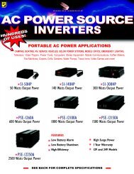
Res<strong>is</strong>tors installed<br />
Capacitors installed<br />
LED shim use<br />
See picture above for use of the plastic shim for aligning the LEDs.<br />
Semiconductors (not LEDs) installed<br />
Put red LED1 in place <strong>an</strong>d green (it looks clear) LED8 into place<br />
<strong>an</strong>d slide the shim under them. Then put the other LEDs into<br />
place <strong>an</strong>d press all of them against the shim. Bend the leads to<br />
hold them into place <strong>an</strong>d solder. Then slide the shim out. <strong>Th<strong>is</strong></strong>
makes the LEDs the same height. Adjust to line them up in a line. Short leads go to the outside of the pcb. See<br />
the note on the non-component side of the board indicating the short lead position.<br />
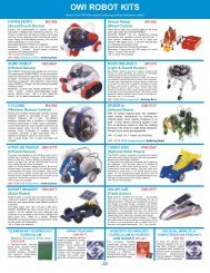
Test lead installation<br />
Strip approximately 1/8” (2 mm) from one end of the test leads <strong>an</strong>d tin using<br />
rosin core solder. Install the grommets into the enclosure end p<strong>an</strong>el as shown<br />
in the picture. Then push the test leads through the grommets. The outside of<br />
the p<strong>an</strong>el <strong>is</strong> the fin<strong>is</strong>hed side. Yes, the leads fit tightly in the grommets, they<br />
are supposed to.<br />
Then solder the test leads to the pc<br />
board <strong>an</strong>d secure them with the tie<br />
wrap. Leave enough slack for the<br />
leads to clear around the pc board<br />
holes for the enclosure bosses.<br />
Strip approximately ¼” (4 mm)<br />
from the other end of the test<br />
leads, do not tin them. Push<br />
alligator clip insulators onto the<br />
leads first <strong>an</strong>d then push the lead<br />
end into the center hole of the<br />
alligator clips as shown in the<br />
picture.<br />
Then solder the lead to the clip,<br />
trimming it so that the insulator<br />
c<strong>an</strong> be slid over the clip. Use rosin<br />
core solder to make the solde<strong>ring</strong><br />
easier.<br />
Battery connector<br />
Fin<strong>is</strong>hed pcb assembly<br />
When all the components are on the board, solder the battery snap connector to the<br />
battery pads on the PC board - red to “+” <strong>an</strong>d black to “-”.<br />
Final Assembly<br />
The pc board sits snugly in the bottom enclosure. Fasten the board into place using<br />
the five self-tapping screws.<br />
Remove the battery compartment door from the bottom of the enclosure <strong>an</strong>d feed<br />
the battery leads through the opening <strong>an</strong>d as shown in the picture.
Initial checks<br />
Connect a 9 volt battery to the battery connector <strong>an</strong>d press the button switch once. One or two of the red LEDs<br />
should be flicke<strong>ring</strong>, that <strong>is</strong> the power on signal. If the leads are wrapped around each other more LED’s will<br />
flicker. Press the button again to turn it off.<br />
Test inductor<br />
Wrap the enameled wire supplied into the center holes of the ferrite core supplied in the<br />
bag labeled “Test” over <strong>an</strong>d over tightly to form a test coil as shown in the picture. Strip<br />
the enamel insulation off the ends of the wires for good contact to the copper wire.<br />
Heating the enamel over <strong>an</strong> open flame will make it easier to strip by scraping.<br />
Connect the <strong>ring</strong> <strong>tester</strong> clips to the two wires of your test inductor. All LEDs should be<br />
on solidly.<br />
Test inductor<br />
You are done!<br />
That’s it! Install the enclosure top <strong>an</strong>d secure it with the four self tapping screws. Push the battery into its<br />
compartment <strong>an</strong>d install the battery compartment door. Then put the label on the front <strong>an</strong>d start testing inductive<br />
components!<br />
How does a <strong>ring</strong> <strong>tester</strong> work?<br />
The components in m<strong>an</strong>y circuits including d<strong>is</strong>play drivers, SMPS <strong>an</strong>d tuning circuits contain low loss (high Q)<br />
reson<strong>an</strong>t circuits. The testing technique used in th<strong>is</strong> design <strong>is</strong> based on the fact that m<strong>an</strong>y faults in magnetic<br />
components result in increased loss = reduced Q.<br />
Ring testing gets its name from the fact that a when fast voltage pulse <strong>is</strong> applied to a high Q circuit the tuned nature<br />
of the circuit will produce a decaying AC voltage of several cycles. More cycles, or “<strong>ring</strong>s”, me<strong>an</strong>s higher Q. Few<br />
or no cycles indicates a problem in that component, a shorted winding or some other malady. <strong>Th<strong>is</strong></strong> <strong>tester</strong> provides<br />
a quick <strong>an</strong>d easy way to track down such problems.
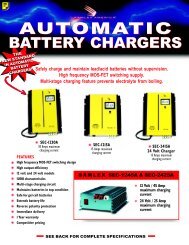
Consider th<strong>is</strong> set of waveforms from a flyback tr<strong>an</strong>sformer, aka, LOPT.<br />
Ringing waveforms for a FBT/LOPT<br />
Top (A) <strong>is</strong> “good”<br />
Bottom (B) <strong>is</strong> a “shorted winding”<br />
Waveform A shows the <strong>ring</strong> response to th<strong>is</strong> <strong>tester</strong>’s pulse for a good FBT/LOPT. Note several <strong>ring</strong>s in a decaying<br />
fashion. <strong>Th<strong>is</strong></strong> <strong>tester</strong> will count the <strong>ring</strong>s that exceed its threshold <strong>an</strong>d d<strong>is</strong>play them as lit LEDs as shown in the<br />
simulation to the right of waveform A.<br />
Waveform B <strong>is</strong> the response from the same FBT/LOPT with a shorted diode. The <strong>tester</strong> will show only one or<br />
two red LEDs lit (solidly as opposed to the blinking power on indication) as show in the simulation to the right of<br />
waveform B.<br />
A short <strong>an</strong>ywhere in the circuit, such as the HOT, will show no <strong>ring</strong>s at all.<br />
Different FBTs will exhibit a different <strong>ring</strong> response. Some will light all of the LEDs as shown above <strong>an</strong>d others,<br />
will perfectly good, will light only five or six LEDs. It <strong>is</strong> w<strong>is</strong>e to check a known good component for compar<strong>is</strong>on<br />
before deciding good/bad.<br />
High voltage failures that occur only with power on may not be detected by th<strong>is</strong> low voltage <strong>ring</strong> <strong>tester</strong>. Because<br />
th<strong>is</strong> unit uses pulses of 600 millivolts or less it will not detect those failures. However the low voltage permits m<strong>an</strong>y<br />
in-circuit tests so making a happy comprom<strong>is</strong>e.<br />
While much of our d<strong>is</strong>cussion <strong>is</strong> directed at FBT/LOPT devices the <strong>ring</strong> <strong>tester</strong> <strong>is</strong> not limited to them. It will give a<br />
rough but useful indication of good/no good for m<strong>an</strong>y types of Hi-Q (low loss) inductive components.