Assembly & Troubleshooting Manual - Main Electronics
Assembly & Troubleshooting Manual - Main Electronics
Assembly & Troubleshooting Manual - Main Electronics

Create successful ePaper yourself
Turn your PDF publications into a flip-book with our unique Google optimized e-Paper software.
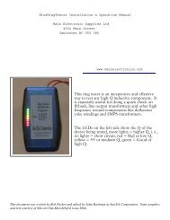
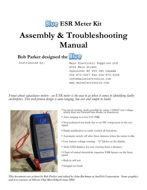
Blue ESR Meter Kit<br />
<strong>Assembly</strong> & <strong>Troubleshooting</strong><br />
<strong>Manual</strong><br />
Blue<br />
Bob Parker designed the Blue<br />
Forget about capacitance meters - an ESR meter is the way to go when it comes to identifying faulty<br />
electrolytics. This well-proven design is auto-ranging, low cost and simple to build.<br />
• In-circuit testing, made possible by using
Parts List and <strong>Assembly</strong> Order<br />
PC board 47K (R4), 4 2.2K (R5, 7. 9,<br />
15)<br />
4 pieces 5 position inline<br />
header strip<br />
1% MF Resistors 6 10K (R1,19,20,21,23,24) Semiconductors<br />
100R (R10)<br />
Miniature pushbutton switch<br />
with cap<br />
470K (R22)<br />
10kΩ PC-mount trim pot<br />
(VR1)<br />
10.0K (R6) 220Ω PC-mount trim pot<br />
(VR2)<br />
1.0K (R8) 3.58MHz crystal resonator<br />
with internal capacitors<br />
4 1N4148 or 1N914 signal<br />
diodes (D1, D2, D5, D6)<br />
2 1N4004, 5, 6 or 7 power<br />
diodes (D3,D4)<br />
7 2N3906 PNP transistors<br />
(Q1, Q3, Q4, Q5, Q8, Q9,<br />
Q10)<br />
6 2N3904 NPN transistors<br />
(Q2. Q6, Q7, Q11, Q12, Q13)<br />
2 3/8” rubber grommets<br />
2 test leads, banana plugs and<br />
alligator clips<br />
3” tie wrap<br />
Miscellaneous<br />
ESR chart label<br />
contact information label<br />
5% Resistors Capacitors<br />
LP2950CZ-5.0 3-terminal<br />
regulator low-dropout (IC1)<br />
220R (R11)<br />
3 100µF 16V RB electrolytic Z86E0412 programmed<br />
(C1, C3, C9)<br />
microcontroller (IC2)<br />
1K (R12), 100K (R13)<br />
22uf, 33uf or 47µF 50V 4094 / MC14094 CMOS<br />
bipolar RB electrolytic (C6) shift<br />
register (IC3)<br />
220K (R14), 180R (R16)<br />
22µF 16/25V RB electrolytic 2 LTS-5503AB 7-segment<br />
(C8)<br />
displays (DIS1, 2)<br />
82.0R for alignment<br />
6.8K (R17), 680R (R18) 470nF 63V MKT (C10) 2 3mm blue LEDs (LED1,2) 5R6 for alignment<br />
3 4.7K (R2, 27, 28) 3 100nF 50V disc or<br />
multilayer (C4,C5,C13)<br />
27K (R25), 2.7K (R29)<br />
33nF 63/100WV (C7)<br />
2 15K (R3, 26), 100R (R30) 10uf 16/25WV electrolytic<br />
(C2)<br />
plastic enclosure with battery<br />
lead and hardware<br />
6 #2 self tapping screws<br />
Value<br />
Resistor Color Codes<br />
4-Band Code (5%) 5-Band Code (1%)<br />
5.60 Ω green blue gold brown green blue black silver brown<br />
82 Ω grey red black brown grey red black gold brown<br />
100 Ω brown black brown brown brown black black black brown<br />
180 Ω brown grey brown brown brown grey black black brown<br />
220 Ω red red brown brown red red black black brown<br />
680 Ω blue grey brown brown blue grey black black brown<br />
1k Ω brown black red brown brown black black brown brown<br />
2.2k Ω red red red brown red red black brown brown<br />
2.7k Ω red violet red brown red violet black brown brown<br />
4.7k Ω yellow violet red brown yellow violet black brown brown<br />
6.8k Ω blue grey red brown blue grey black brown brown<br />
10k Ω brown black orange brown brown black black red brown<br />
15k Ω brown green orange brown brown green black red brown<br />
27k Ω red violet orange brown red violet black red brown<br />
47k Ω yellow violet orange brown yellow violet black red brown<br />
100k Ω brown black yellow brown brown black black orange brown<br />
220k Ω red red yellow brown red red black orange brown<br />
470k Ω yellow violet yellow brown yellow violet black orange brown
Construction<br />
Even if the ESR Meter’s<br />
operation seems<br />
complicated, at least it is<br />
easy to build. As you can<br />
see in the photos, all the<br />
components are mounted<br />
on a single PC board<br />
which is then attached to<br />
the enclosure bottom.<br />
Even though the pc<br />
board is high-quality with<br />
solder-mask it is still wise<br />
to check it for defects.<br />
To do this, illuminate the<br />
component side with a<br />
bright light and examine<br />
the copper side very<br />
carefully – preferably with<br />
a magnifier – for any<br />
hairline fractures in the<br />
tracks.<br />
During assembly<br />
frequently check for any<br />
solder “whiskers” or<br />
bridges and pay particular<br />
attention to any tracks,<br />
which pass between IC<br />
pads, where such defects<br />
tend to congregate and<br />
hide. It is good practice<br />
to install 5 or 6<br />
components and then<br />
check the soldering of<br />
them under a magnifier.<br />
Then move on and install<br />
5 or 6 more.<br />
The PC board is tightly<br />
packed and the solder<br />
pads are quite small so be<br />
very careful with your<br />
soldering. Always lift the<br />
iron vertically from a just<br />
soldered joint and never<br />
wipe it sideways as so<br />
many constructors seem<br />
to do!
Component Installation Sequence<br />
The kit package contains six plastic bags of components and one bag of static sensitive components. Install them in<br />
the following order:<br />
1% resistors<br />
5% resistors<br />
Semiconductors (Do not install the decimal LEDs until after installing the 7-segment displays. See Install<br />
LED Displays.)<br />
Capacitors<br />
Miscellaneous parts<br />
Static Sensitive components (Do not install the integrated circuits until after performing the Initial<br />
Checks.)<br />
The bag labeled “For alignment and test” contains two resistors that are used for that purpose and are not installed<br />
on the pc board.<br />
Installing components<br />
The construction sequence basically installs the smallest components first. It is notoriously difficult to correctly<br />
identify the color bands on 1% resistors so check each one’s value with an ohmmeter before soldering it to the<br />
board. The table of color codes above will help you select the resistor values prior to checking.<br />
It is a good idea to check the value of all of the resistors with an ohm meter as manufacturers occasionally make<br />
labeling mistakes.<br />
Take care with the orientation of the polarized components: the electrolytic capacitors, diodes, and transistors. You<br />
should also make sure that the two different transistor types go into their correct places.<br />
Note that there is provision on the pc board for two 27 pf capacitors near the crystal. Your kit has a crystal<br />
resonator with internal capacitors supplied so that those two components are not needed.<br />
After you have the small parts installed and soldered into place you can install the larger components. These parts<br />
include crystal XTAL1, the electrolytic capacitors, trim-pots VR1 & VR2, the transistors, and the headers for the<br />
LED displays.<br />
Note particularly that the 7-segment LED displays are each mounted on two 5 pin headers which are soldered to<br />
the pc board (see picture below). Make sure that the headers are absolutely vertical and flush with the pc board<br />
before soldering the pins so that the displays will fit properly under the enclosure cover.<br />
OPTION: Some kit builders are nervous about soldering directly to the integrated circuit pins and prefer to install<br />
sockets for that reason. Feel free to do so although sockets are not included in the kit. If you solder your<br />
integrated circuits and manage to damage them in doing so contact AnaTek. We will replace the integrated circuits<br />
for FREE!
Miscellaneous parts – see text<br />
for display header installation.<br />
The headers must be installed<br />
carefully to ensure proper<br />
alignment of the 7-segment<br />
displays.<br />
Strip and tin the one end of<br />
the test lead ends. Put the two<br />
grommets into the test lead<br />
holes in the enclosure end<br />
panel. Then feed the test<br />
leads through the grommets.<br />
The outside of the panel is the<br />
finished side.<br />
Test lead connection. Note<br />
the tie wrap retainer.
Test lead installation<br />
Strip approximately 1/8” (2 mm) from one end of the test leads and tin using rosin core solder. Install the<br />
grommets into the enclosure end panel as shown in the picture. Then push the test leads through the grommets.<br />
The outside of the panel is the finished side<br />
Then solder the test leads to the pc board and secure them with the<br />
tie wrap. Leave enough slack for the leads to clear around the pc<br />
board holes for the enclosure bosses.<br />
Strip approximately 1/2” (12 mm) from the other end of the test<br />
leads, do not tin them but bend the bare wire back on itself. Push<br />
the banana plug insulators onto the leads first and then push the<br />
bare wire end into the center hole of the banana jacks so that it is<br />
lined up with the securing screw as shown in the picture on the left.<br />
Banana Plug assembly<br />
Slide the insulator over the banana plug and screw the retaining<br />
screw in tightly.<br />
Install LED displays<br />
Before handling the 7-segment displays make sure that you are grounded as they are sensitive to static electricity.<br />
Orient the 7-segment displays with their decimal points toward the bottom of the pc board (battery connection end)<br />
and push the pins into headers making sure that they are fully seated. Then insert the two decimal point LEDs such<br />
that the tops of the LEDs are the same height as the 7-segment displays. Make sure that they are correctly oriented;<br />
ie, the shorter lead must go toward the 7-segment displays. The top of the decimal LEDs should be flush with the<br />
top of the 7-segment displays.<br />
DO NOT INSTALL THE INTEGRATED CIRCUITS YET!<br />
Once everything except the integrated circuits are on the PC board,<br />
hold the component side up to a bright light and carefully check for<br />
any solder bridges or other problems. In particular, check for light<br />
shining through the holes of unsoldered joints.<br />
7-segment displays and decimal LEDs<br />
installed<br />
Battery connector<br />
When all the components are on the board, solder the battery snap<br />
connector to the battery pads on the PC board - red to “+” and black<br />
to “-”.
Initial checks<br />
With IC2 and IC3 still not installed connect the supply leads to the batteries (or a 9V DC power supply), with a<br />
milliammeter in series with one of the supply leads. Note, some digital multimeters have too high an impedance to<br />
be useful for this test.<br />
Initially, you should not see any current being drawn. Press and hold the pushbutton switch and check that the<br />
current drawn is between 3 and 5 milliamps (the current will initially pop higher as all of the capacitors charge). If it<br />
is significantly higher or lower, start looking for assembly errors (component placement errors, missed solder joints<br />
and solder splashes).<br />
Assuming the current checks OK, connect the negative lead of a voltmeter to the negative battery lead, then check<br />
that there’s +5V on pin 5 of IC2 (18 pin) and on pin 16 of IC3 (16 pin).<br />
If everything is OK, disconnect the 9V supply and the milliammeter. That done, discharge any static electricity you<br />
may have accumulated by touching something earthed, then install IC2 (Z86E041) and IC3 (4094). Double-check<br />
to ensure that these are both oriented correctly – their indented pin 1 ends are to the left.<br />
Next, set both VR1 and VR2 to their mid-range positions and reconnect the 9V supply. Press the pushbutton, you<br />
should see something on the 7-segment LED displays, hopefully “-” on the left hand one.<br />
Press the pushbutton again and the meter should turn off.<br />
Turn it back on and short the leads together. The meter should read something less than 0.5 ohm. With the leads<br />
shorted press the pushbutton again to zero the test leads. The reading should be “.00” with the left decimal lit. The<br />
reading may bounce around +.02 ohms or so due to variation in the lead contact resistance.<br />
Calibration<br />
It is best to calibrate the unit before assembling it into the box. That way you can correct any assembly errors that<br />
show up during calibration without having to disassemble the board from the box.<br />
With the meter on and the leads zeroed as described above connect the supplied 82Ω 1% calibration resistor to the<br />
probes and carefully adjust VR2 until the meter reads “82.” Then check that that it reads the supplied 5.6Ω<br />
calibration resistor reasonably accurately (5.2 to 6.0) with the middle decimal lit.<br />
Battery warning setup<br />
Skip this bit if you disabled the automatic switch-off function by leaving one lead of R25 disconnected (see the<br />
“Optional Modifications” section).<br />
This adjustment is easiest if you have access to a variable DC power supply. If not, you will need to build the little<br />
circuit shown here.<br />
The adjustment procedure is as follows:<br />
(1) With the ESR meter off and nothing<br />
attached to the test leads turn VR1 (10K<br />
ohm) fully clockwise (as viewed from the<br />
component side of the PC board).
(2) Adjust the supply voltage to 5.5 volts, then switch the meter on.<br />
(3) Slowly turn VR1 counter clockwise until the “b” battery warning indication begins flashing on the right hand<br />
display.<br />
(4) Turn the meter off, wind the power supply back up to 9 volts, then switch the meter back on and check that the<br />
battery warning triggers when you drop the supply back to 5.5 volts.<br />
Final <strong>Assembly</strong><br />
The pc board sits snugly in the bottom enclosure. Fasten the board<br />
into place using the six self-tapping screws. The screw under the tiewrapped<br />
test leads may be difficult to get into place. You can omit it.<br />
Remove the battery<br />
compartment door<br />
from the bottom of<br />
the enclosure and<br />
run the battery leads<br />
through the opening<br />
and as shown in the<br />
picture.<br />
Final <strong>Assembly</strong><br />
You are done!<br />
Battery Lead Dress<br />
That’s it! Install the enclosure top and secure it with the four self tapping screws. Push the battery into its<br />
compartment and install the battery compartment door. Then put the labels on the front and start finding bad caps!<br />
Before using your new meter we recommend that you read the section on ESR meter operation – it not only<br />
contains useful hints but also lists precautions that you should follow.<br />
What is bad ESR?<br />
There is a chart of 3 X normal average ESR for various capacitor values and voltage ratings on the meter front<br />
panel. There is no one bad value; it depends upon the rating of the capacitor you are testing.<br />
In general, a capacitor with bad ESR will read at least 2 – 3 times the values given for a new capacitor by the<br />
manufacturer. The values shown on the chart are generally 3 times the manufacturer’s specs. A really bad one<br />
might be 10 times the values shown or more.<br />
With experience you will be able recognize bad ones without consulting the chart.<br />
Basic operation<br />
The ESR Meter is extremely simple to operate but there are a few precautions to follow. Here is its basic step-bystep<br />
operation:
(1). Insert the probe terminator of your choice into the shrouded plugs. A croc clip works well for out of circuit<br />
capacitors, a probe for in-circuit.<br />
(2). Press the button so the “-” symbol appears on the display.<br />
(3). Hold the test probes tightly together – the test lead resistance is displayed.<br />
(4). With the probes still together, press the button again to give a zeroed reading of “.00”. You can repeat this at<br />
any time.<br />
(5). Measure the capacitor’s ESR (it should be discharged first). A reading of “-” indicates a reading greater than<br />
99Ω. Compare the reading to the graph on the front label. Good capacitors will have ESR below the graph lines,<br />
bad above.<br />
(6). When you’ve finished measuring, press the button with the probes separated. The meter switches off when<br />
you release the button.<br />
(7). When the battery is getting low, “b” flashes once per second and the display dims to conserve the remaining<br />
battery capacity.<br />
Precautions<br />
(1). Beware charged capacitors:<br />
The very first thing to do is to make certain that the equipment you’ll be using the ESR Meter on is disconnected<br />
from all power. Most electrolytic capacitors will be discharged by the circuitry around them within a few seconds of<br />
the power being switched off. However, be warned that filter capacitors in power supplies can remain<br />
dangerously charged, especially if there’s a fault. Before using the meter, make sure that all power supply capacitors<br />
are fully discharged. You can do this using well-insulated probes that include a series 100Ω 5W or similar power<br />
resistor. Do not just short the capacitor’s terminals together as that can not only damage the capacitor but can also<br />
be dangerous. Always allow several seconds to ensure a complete discharge. Apart from the risk of surprise and<br />
injury to you, large charged capacitors can seriously damage the meter.<br />
(2). Watch out for interference:<br />
The meter can produce unsteady indications if its test leads pick up strong horizontal deflection signal voltages. To<br />
avoid this, be sure to keep it away from operating (CRT) TVs and monitors when making measurements.<br />
(3). Use straight test leads:<br />
Do not add self-retracting “curly” test leads with your meter. Their inductance can cause measurement errors.<br />
What else can it do?<br />
Since publication of the Mk.1 design in 1996, I have received a lot of feedback from imaginative ESR Meter users<br />
regarding other uses for it. The full list is on at<br />
http://members.ozemail.com.au/ ~bobpar/esrhints.htm but here are some of the best ones:<br />
(1). Resistance Measurement: as stated previously, this meter is really an AC ohmmeter with an equivalent test<br />
frequency of about 100kHz and capable of measuring non-inductive resistances from 0.01Ω to 99Ω. As such, it can<br />
be useful for locating short circuits on PC boards by showing the resistance of a copper track decreasing or<br />
increasing as you approach or move away from the short. For example, this is useful when trying to identify which<br />
one in a paralleled set of power transistors is shorted (thanks Mike Diack) or the check out power leads and<br />
connectors (resistance is too low for a multimeter).
You can also make your own very low-value resistors by measuring out a length of nichrome or similar resistance<br />
wire to give the required resistance. In addition, the ESR Meter can be used to check the contact resistance of<br />
switches, connectors and relays. Just remember that any significant amount of inductance will cause measurement<br />
errors. You cannot measure the DC resistance of a choke, transformer winding, video head or a roll of electrical<br />
cable, for example.<br />
(2). Basic Signal Generator: the meter’s test signal is a 500mV P-P (open circuit) burst of 8 usec pulses at a 2kHz<br />
rate, repeated several times per second. As a result, it can be used as a signal source for basic checks on amplifiers,<br />
loudspeakers and other audio components (thanks Joe Lussy). Richard Newstead (our UK distributor) reports that<br />
the meter can be used as a simple wideband signal generator with useful signals out to 30 Mhz.<br />
(3.)<br />
<strong>Main</strong>tenance<br />
The meter’s readings might become unsteady after a lot of use, due to oxidation or loosening of the test lead s.<br />
Heavily spray the test lead plugs with contact cleaner of the kind which evaporates completely (eg, CRC “CO”<br />
Contact Cleaner), then repeatedly insert and withdraw them from their s before it dries. If the test lead s have<br />
become loose, gently re-tighten them with long needle-nose pliers.<br />
If the test probes have developed a resistive layer of oxidation, give them a wipe with a tissue soaked in tuner<br />
cleaner like CRC 2.26 or similar (thanks Joe Sopko).<br />
It does not work, now what?<br />
The ESR Meter’s firmware allows the microcontroller to do some basic testing of the electronics to help you<br />
narrow down a problem to one area of the board. Before doing the self-test, it’s very important to first set VR1<br />
to the center of its adjustment range and make sure that the meter’s supply voltage is in the range of 6.2 –<br />
6.8V. You cannot use the 9 volt battery for this test. Also short out R30, 100R.<br />
Switch the meter on by pressing and continuing to hold the button down, regardless of what the displays are<br />
showing. After five seconds, they will go blank for a moment and then show a test result for two seconds. The<br />
meter will then switch off by itself after you release the button.<br />
If everything is more or less OK, you’ll see “.8.8” on the displays (this shows that all the display segments and<br />
decimal point LEDs are working). However, if the microcontroller has detected a problem it will flash a fault code<br />
consisting of an “F” on the left hand display and a character from 0-9 or an “A” on the right hand one.<br />
Experience has shown that by far the most common cause of ESR meter kits not working properly is defective<br />
soldering. When a fault code directs you to a particular part of the circuit, carefully check (using a bright light and<br />
magnifier) for solder whiskers, non-soldered joints and track damage such as lifted solder pads.<br />
If you cannot see anything abnormal, start checking for incorrect components and component placement errors<br />
such as transistors of the wrong type or with their leads in the wrong holes. If that does not show up anything, you<br />
might have received a defective component in the kit, though this is very rare. OK, here is a list of what the fault<br />
codes indicate:<br />
F0: Q11 is not discharging C10. Check around Q11 (2N3904), R21 (10kΩ), R22 (470kΩ) and pin 4 of IC2<br />
(Z86E0412).<br />
F1: C10 is charging too quickly. Check that R22 really is 470kΩ and that R19 & R20 are 10kΩ. Make sure C10 is<br />
470nF (0.47µF, code “474”). Check also for soldering and component placement problems around transistors Q9 &<br />
Q10 (2N3906).
F2: C10 is charging too slowly (or not at all). Check around Q9, Q10 (2N3906), R22 (470kΩ), R19 & R20 (10kΩ)<br />
and C10 (470nF).<br />
F3: Pulse amplifier output bias 1V. Carry out the same checks as for “F3” code. Check also that D5 isn’t<br />
reversed.<br />
F5: A test current source is permanently on. Check area around Q3, Q4 & Q5 (all 2N3906); R5, R7 & R9 (2.2kΩ);<br />
and pins 15, 16 & 17 of IC2.<br />
F6: No output from pulse amplifier. Check around C7 (33nF), R12 (1kΩ), D3 & D4 (1N4002), C5 (100nF) and C6<br />
(47µF bipolar).<br />
F7: Q3 not sourcing current. Check around Q3 (2N3906), R5* (2.2kΩ), R6 (10kΩ) and pin 15 of IC2.<br />
F8: Q4 not sourcing current. Check around Q4 (2N3906), R7* (2.2kΩ), R8 (1kΩ) and pin 16 of IC2. F9: Q5 not<br />
sourcing current. Check around Q5 (2N3906), R9* (2.2kΩ), R10 (100Ω), IC2 pin 17.<br />
F9: Q5 not sourcing current. Check around Q5 (2N3906), R9* (2.2kΩ), R10 (100Ω), IC2 pin 17.<br />
FA: Q6 not switching on. Check around Q6 (2N3904), R24 (10kΩ) and pin 1 of IC2. The microcontroller cannot<br />
perform detailed tests on every component, so it’s possible that your meter is malfunctioning even though the selftesting<br />
hasn’t shown up a problem. For example, if the meter is behaving strangely, “freezing” up or giving absurd<br />
readings on some values of test resistors, the most likely cause is a mix-up in the values of R6 (10kΩ), R8 (1kΩ) and<br />
R10 (100Ω). On the other hand, if the meter produces readings but there’s something wrong with the displayed<br />
characters, this is almost certainly due to one or more solder bridges between the pins of the displays or around IC3.<br />
If the meter does not stay switched on when you push the button, check around Q2 (2N3904), R3 (15kΩ), R29<br />
(2.7kΩ) and pin 2 of IC2. If it switches off when you short the test leads, R2 (4.7kΩ) may be the incorrect value or<br />
Q1 (2N3906) may have a low current gain. Finally, if you can’t get the meter into the test mode, zero it or switch it<br />
off, check for solder “whiskers” and open circuits around pin 3 of IC2, R4 (47kΩ) and D2.<br />
If none of the above has helped you to identify the problem, there is a page of fault-finding information on my<br />
website: http://members.ozemail.com.au/ ~bobpar/esrprob.htm. Do a Google search for “ESR meter<br />
faultfinding” if you can’t find it.<br />
Disabling automatic switch-off<br />
If you’d like to power the meter from an external 9V DC supply and have it operating continuously, just disconnect<br />
one end of R25 (47kΩ). This disables the automatic switch-off function but note that the low battery warning will<br />
no longer work if you do this.<br />
Of course, you can easily reconnect R25 if you change your mind in the future.<br />
For more modifications, including a buzzer to help you discriminate between good and bad electrolytics without<br />
having to look at the meter, go to my ESR Meter Hints web page at http://members.ozemail.com.<br />
au/~bobpar/esrhints.htm. If all else fails send a question to esrquestion@anatekcorp.com.