LSU-4.9 Data - RB Racing
LSU-4.9 Data - RB Racing
LSU-4.9 Data - RB Racing

Create successful ePaper yourself
Turn your PDF publications into a flip-book with our unique Google optimized e-Paper software.
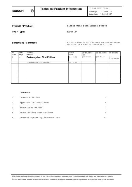
Technical Product Information<br />
Y 258 E00 015e<br />
Seite/Page 1 von/of 13<br />
Datum/Date 14.6.2005<br />
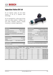
Produkt / Product:<br />
Typ / Type:<br />
Planar Wide Band Lambda Sensor<br />
<strong>LSU</strong><strong>4.9</strong><br />
Bemerkung / Comment:<br />
All data given in this document are nominal values<br />
and might be subject of change at all time.<br />
Nr.<br />
Index<br />
Seite<br />
Page<br />
Änderung<br />
Revision<br />
Datum<br />
Date<br />
GS-EX/ENG6-<br />
Ham<br />
GS-EX/ENG6<br />
GS-EX/ENG<br />
1 - Erstausgabe / First Edition 14.6.05 gez Hamann gez Meier gez.<br />
Stanglmeier<br />
translation to English 26.8.05<br />
Contents<br />
1. Characteristics 2<br />
2. Application conditions 5<br />
3. Functional values 7<br />
4. Installation instructions 9<br />
5. General operating instructions 12<br />
©Alle Rechte bei Robert Bosch GmbH, auch für den Fall von Schutzrechtsanmeldungen. Jede Verfügungsbefugnis, wie Kopier- und Weitergaberecht, bei uns.<br />
©Robert Bosch GmbH reserves all rights even in the event of industrial property.We reserve all rights of disposal such as copying and passing on to third parties
Technical Product Information<br />
Y 258 E00 015e<br />
Seite/Page 2 von/of 13<br />
Datum/Date 14.6.2005<br />
General<br />
The wide band lambda sensor <strong>LSU</strong> is a planar ZrO 2 dual cell limiting current<br />
sensor with an integrated heater. It is used to measure the oxygen content<br />
and the λ-value of exhaust gases in automotive engines (gasoline and diesel).<br />
Its monotonic output signal in the range of λ=0.65 to air makes the<br />
<strong>LSU</strong> capable of being used as an universal sensor for λ=1 measurement as<br />
well as for other λ ranges.<br />
The connector module contains a trimming resistor, which defines the<br />
characteristics of the sensor and is necessary for the sensor function.<br />
The wide band sensor <strong>LSU</strong> operates only in combination with a special<br />
<strong>LSU</strong> control unit (e.g. AWS control box, LA4 or CJ125 IC).<br />
1. Characteristics<br />
1.1 Circuit of <strong>LSU</strong> and control unit<br />
Sensor Cell<br />
AWS<br />
O 2 , CO, HC, H 2<br />
APE ← Ip<br />
red IP<br />
Trimming Resistor<br />
30-300 Ohm<br />
green<br />
IA<br />
← Ip meas<br />
Measuring<br />
Resistance 61.9 Ohm<br />
+<br />
−<br />
IPN<br />
RE<br />
yellow<br />
VM=2,5V<br />
U N<br />
O 2− +<br />
O 2− 20 µA Reference Pump Current<br />
Reference<br />
Voltage<br />
450 mV<br />
−<br />
R V<br />
V CC<br />
black<br />
R i -control<br />
H -<br />
H +<br />
white<br />
grey<br />
−<br />
+<br />
1.2 Electrical connection:<br />
Pin1: Pumping Current APE<br />
Pin2: Virtual Ground IPN<br />
Pin3: Heater Minus H-<br />
Pin4: Heater Vbatt H+<br />
Pin5: Trim Current RT<br />
Pin6: Nernst Voltage RE+<br />
red<br />
yellow<br />
white<br />
grey<br />
green<br />
black<br />
©Alle Rechte bei Robert Bosch GmbH, auch für den Fall von Schutzrechtsanmeldungen. Jede Verfügungsbefugnis, wie Kopier- und Weitergaberecht, bei uns.<br />
©Robert Bosch GmbH reserves all rights even in the event of industrial property.We reserve all rights of disposal such as copying and passing on to third parties
Technical Product Information<br />
Y 258 E00 015e<br />
Seite/Page 3 von/of 13<br />
Datum/Date 14.6.2005<br />
1.3 Sensor element<br />
The heater supply voltage must be controlled, so that the temperature of<br />
the sensor is kept at the operation point. The temperature is measured by<br />
measuring the internal resistance of the sensor’s Nernst cell R i,N<br />
Nominal internal resistance of λ=1 Nernst cell R i,N<br />
for new sensors (operating and calibration point)<br />
(measured with AC f = 1...4 kHz)<br />
300 Ω<br />
Max. current load of λ=1 Nernst cell<br />
Continuous AC (f = 1...4 kHz) ≤ 250 µA<br />
for R I,N measurement<br />
Recommended value for reference pumping current<br />
continuous = 20 µA<br />
Max. pumping current into pump cell (I p )<br />
- for rich gas signal (λ≥0,65) ≥ -9 mA<br />
- for lean gas signal (air) ≤ 6 mA<br />
1.4 Isolation resistance<br />
(all values for new sensors in static air, heater off)<br />
- between housing and each heater- and<br />
sensor circuit connector pin at room<br />
temperature<br />
- between sensor signal circuit and heater<br />
circuit at 600°C hexagon temperature<br />
- between sensor signal pin APE and housing<br />
at 600°C hexagon temperature:<br />
≥ 30 MΩ<br />
≥ 1 MΩ<br />
≥ 100 kΩ<br />
©Alle Rechte bei Robert Bosch GmbH, auch für den Fall von Schutzrechtsanmeldungen. Jede Verfügungsbefugnis, wie Kopier- und Weitergaberecht, bei uns.<br />
©Robert Bosch GmbH reserves all rights even in the event of industrial property.We reserve all rights of disposal such as copying and passing on to third parties
Technical Product Information<br />
Y 258 E00 015e<br />
Seite/Page 4 von/of 13<br />
Datum/Date 14.6.2005<br />
1.5 Heater supply<br />
Nominal voltage:<br />
Nominal heater power at 7.5 V heater supply<br />
at thermal equilibrium in air:<br />
Nominal heater cold resistance at room temp.<br />
for new sensor, including cable and connector<br />
Minimum heater cold resistance at -40°C:<br />
7.5 V<br />
approx. 7.5 W<br />
3.2 Ω<br />
1.8 Ω<br />
1.6 When the heater is switched on, heater power must be limited as follows:<br />
effective heater voltage<br />
V Heff [V]<br />
operating point reached<br />
13 V<br />
heater power reduced<br />
during condensation<br />
water phase<br />
//<br />
max. value<br />
13Volt<br />
8.5V<br />
maximum<br />
ramp rate<br />
= 0.4V/s<br />
//<br />
max. initial value<br />
8.5V<br />
application specific<br />
← application specific → time after heater start<br />
Maximum permissible heat up rate with limited heater power to reduce the thermal stresses in<br />
the heat-up phase<br />
During the condensation water phase the heater power must be limited to<br />
rule out thermo shock damage of the sensor ceramic.<br />
Heater voltage during condensation water phase V H,eff ≤ 2 V<br />
Maximum permissible effective heater voltage V H,eff<br />
to reach the operating point<br />
- short time ≤ 30sec (200h cumulated time): ≤ 13 V<br />
- continuous: ≤ 12 V<br />
Maximum system supply voltage V batt,max<br />
≤ 16.5 V<br />
Minimum system supply voltage<br />
≥ 10.8 V<br />
at this system supply voltage the function of the sensor is given in<br />
typical applications. This must still be tested in the resp. application.<br />
Minimum frequency of heater voltage control ≥ 20 Hz<br />
- recommended value: ≥ 100 Hz<br />
Note: the use of the sensor with 24V power systems is<br />
not permissible except if a voltage converter system is used.<br />
Note: duty cycle = (V H,eff / V batt ) 2<br />
©Alle Rechte bei Robert Bosch GmbH, auch für den Fall von Schutzrechtsanmeldungen. Jede Verfügungsbefugnis, wie Kopier- und Weitergaberecht, bei uns.<br />
©Robert Bosch GmbH reserves all rights even in the event of industrial property.We reserve all rights of disposal such as copying and passing on to third parties
Technical Product Information<br />
Y 258 E00 015e<br />
Seite/Page 5 von/of 13<br />
Datum/Date 14.6.2005<br />
2. Application conditions<br />
2.1 Temperature measurements<br />
Temperature measurements are performed with a special sensor equipped with<br />
NiCrNi thermocouples, see sketch. Sensor Type "MABCD" has measurement<br />
points at the upper side of the PTFE formed hose (T upperhose ), the cable grommet<br />
(T grommet ), the hexagon of the sensor housing (T hexagon ) and for the exhaust<br />
gas temperature (T exhaustgas ). These sensors are available from Bosch.<br />
T Exhaustgas T Grommet T Upperhose<br />
T Hexagon<br />
2.2 Operating temperatures<br />
Exhaust gas (T Exhaustgas ): ≤ 930°C<br />
Hexagon of the sensor housing (T Hexagon ): ≤ 600°C<br />
Cable grommet (PTFE formed hose)<br />
- sensor side (T Grommet ): ≤ 250°C<br />
- cable side (upperhose crimp, T Upperhose ): ≤ 200°C<br />
Cable and protective sleeve: ≤ 250°C<br />
Connector: ≤ 120°C<br />
2.3 Maximum temperatures<br />
2.3.1 (max. 250 h accumulated over lifetime)<br />
Exhaust gas (T Exhaustgas ): ≤ 1030°C<br />
Hexagon of the sensor housing (T Hexagon ): ≤ 680°C<br />
2.3.2 (max. 40 h accumulated over lifetime)<br />
Cable grommet (PTFE formed hose)<br />
- sensor side (T Grommet ): ≤ 280°C<br />
- cable side (upperhose crimp, T Upperhose ): ≤ 230°C<br />
Cable and protective sleeve: ≤ 280°C<br />
©Alle Rechte bei Robert Bosch GmbH, auch für den Fall von Schutzrechtsanmeldungen. Jede Verfügungsbefugnis, wie Kopier- und Weitergaberecht, bei uns.<br />
©Robert Bosch GmbH reserves all rights even in the event of industrial property.We reserve all rights of disposal such as copying and passing on to third parties
Technical Product Information<br />
Y 258 E00 015e<br />
Seite/Page 6 von/of 13<br />
Datum/Date 14.6.2005<br />
2.4 Exhaust gas pressure (absolute pressure)<br />
- continuous: ≤ 2.5 bar<br />
- short time, max. 250h cumulated over lifetime ≤ 4 bar<br />
Notes:<br />
If the operating temperature ( 2.2) or the max. continuous exhaust gas<br />
pressure ( 2.4) is exceeded, the sensor accuracy might be limited during<br />
this time.<br />
2.5 Permissible vibrations<br />
Stochastic vibrations: (peak level) ≤ 1000 m/s 2<br />
Sinusoidal vibrations: ≤ 300 m/s 2<br />
2.6 Corrosion, humidity<br />
The lambda sensor has been developed and tested for use in automotive vehicles,<br />
e.g.<br />
- damp heat cycling acc. to IEC 68-2-30 test Db (21 days, 40°C)<br />
- salt mist test acc. to IEC 68-2-11 test Ka, test time 288 h<br />
- temperature cycling test acc. to IEC 68-2-14 test Na,<br />
250 cycles -40°C / 130°C<br />
- sulfur dioxide test with general condensation of moisture acc. to DIN EN<br />
ISO 6988, 6 cycles of 24h<br />
- submergence test IPx7 acc. to IEC 529<br />
2.7 Permissible fuel additives<br />
In accordance with DIN EN228 for commercially available unleaded fuel or<br />
EN590 for diesel fuel.<br />
Contamination by other fuels, additives or oil consumption must be determined<br />
by the customer by the way of adequate large-scale tests.<br />
©Alle Rechte bei Robert Bosch GmbH, auch für den Fall von Schutzrechtsanmeldungen. Jede Verfügungsbefugnis, wie Kopier- und Weitergaberecht, bei uns.<br />
©Robert Bosch GmbH reserves all rights even in the event of industrial property.We reserve all rights of disposal such as copying and passing on to third parties
Technical Product Information<br />
Y 258 E00 015e<br />
Seite/Page 7 von/of 13<br />
Datum/Date 14.6.2005<br />
3. Functional values<br />
All data must be regarded as nominal values, measured under the following<br />
conditions:<br />
The sensor is operated with circuit as in section 1.1. The heater power is<br />
closed-loop controlled, so that the nominal sensor internal resistance is<br />
reached. The measurement is done in a lab test bench at p gas =1013hPa.<br />
Changes in the test gas composition, especially of the H 2 -concentration,<br />
will have an influence on the characteristics of the sensor. These influences<br />
are stronger in rich gas than under lean gas conditions.<br />
3.1 Nominal characteristic line<br />
I P meas / mA<br />
3,000<br />
2,500<br />
2,000<br />
1,500<br />
gas: O 2 in N 2<br />
1,000<br />
calibration point<br />
0,500<br />
0,000<br />
0 5 10 15 20 25<br />
-0,500<br />
O 2 -concentration x O2 / %<br />
I P meas / mA<br />
1,500<br />
1,000<br />
0,500<br />
lean gas: O 2 in N 2<br />
λ = (x O2 / 3 +1) / (1-4.77*x O2 ) for H/C=2<br />
0,000<br />
0,70 0,80 0,90 1,00 1,1 1,20 1,30 1,40 1,50 1,60 1,70 1,80 1,90 2,00 2,10 2,20 2,30 2,40 2,50<br />
-0,500<br />
λ<br />
-1,000<br />
rich gas mixture of synthetic gas<br />
9%CO, 7%H 2, 7%CO 2 in N 2<br />
-1,500<br />
-2,000<br />
O 2 -conc. x O2 /% 3.0 6.0 8.29 12.0 20.95<br />
λ-value 0.65 0.70 0.80 0.90 1.016 1.18 1.43 1.70 2.42 air<br />
I p,meas /mA -2.22 -1.82 -1.11 -0.50 0.00 0.33 0.67 0.94 1.38 2.54<br />
©Alle Rechte bei Robert Bosch GmbH, auch für den Fall von Schutzrechtsanmeldungen. Jede Verfügungsbefugnis, wie Kopier- und Weitergaberecht, bei uns.<br />
©Robert Bosch GmbH reserves all rights even in the event of industrial property.We reserve all rights of disposal such as copying and passing on to third parties
Technical Product Information<br />
Y 258 E00 015e<br />
Seite/Page 8 von/of 13<br />
Datum/Date 14.6.2005<br />
3.2 Time to activity (light-off time)<br />
Guide value for the time to activity after switching<br />
on the sensor heater (“light-off time”)<br />
≤ 10 s<br />
3.3 Pressure dependency of the sensor signal<br />
A change of the exhaust gas pressure leads to a deviation of the sensor<br />
signal, which can be approximately described as follows:<br />
25,0%<br />
20,0%<br />
15,0%<br />
10,0%<br />
5,0%<br />
0,0%<br />
-5,0%<br />
-10,0%<br />
-15,0%<br />
-20,0%<br />
∆Ip/Ip(1013 hPa)<br />
lambda > 1<br />
lambda < 1<br />
-25,0%<br />
0,5 0,7 0,9 1,1 1,3 1,5 1,7 1,9 2,1 2,3 2,5<br />
absolute pressure<br />
Absolut-Druck in [bar]<br />
3.4 Temperature dependency of the sensor signal and the internal resistance of<br />
the Nernst-cell R i,N<br />
A temperature change of the sensor ceramic gives a deviation of the sensor<br />
output signal of approx. ∆I P,meas /I P,meas = 4%/100°C<br />
The temperature is known by measuring the internal resistance of the Nernst<br />
cell R I,N and the following curve:<br />
Nernst cell resistance RIN / Ohm<br />
1000<br />
100<br />
operating point<br />
R I,N = 300Ω,<br />
T ceramic = 780°C<br />
10<br />
600 700 800 900 1000 1100 1200<br />
Tceramic / °C<br />
©Alle Rechte bei Robert Bosch GmbH, auch für den Fall von Schutzrechtsanmeldungen. Jede Verfügungsbefugnis, wie Kopier- und Weitergaberecht, bei uns.<br />
©Robert Bosch GmbH reserves all rights even in the event of industrial property.We reserve all rights of disposal such as copying and passing on to third parties
Technical Product Information<br />
Y 258 E00 015e<br />
Seite/Page 9 von/of 13<br />
Datum/Date 14.6.2005<br />
4. Installation instructions<br />
The lambda sensor has been developed and tested for use in automotive engines<br />
only.<br />
The sensor installation point and the sensor functionality in the full system<br />
must be assured sufficiently by the customer through appropriate vehicle<br />
tests under realistic conditions of use.<br />
4.1 Installation in the exhaust system must be at a point guaranteeing representative<br />
exhaust gas composition whilst also satisfying the specified temperature<br />
limits.<br />
4.2 The heater power must always be switched on power controlled (e.g. duty<br />
cycled heater power), starting with a maximum ramp-up duty cycle as shown<br />
in the diagram in section 1.6. This is necessary to reduce thermal stress<br />
of the sensor element during cold starts due to high peak power in the<br />
first seconds.<br />
4.3 The sensor ceramic element is heated up quickly after heater start.<br />
After heating up the ceramic all occurrence of condensation water, which<br />
could damage the hot ceramic, must be ruled out.<br />
To allow early heating of the sensor to reach a fast sensor activity, the<br />
sensor installation location design must be selected in a way to minimize<br />
exhaust-side stressing of the sensor with condensation water.<br />
If this is not possible by design measures, the start of the sensor heater<br />
must be delayed until demonstrably no more condensation water appears.<br />
4.3.1 Design measures:<br />
- Locate sensor as close to the engine as possible, respecting max. allowed<br />
temperature range<br />
- The exhaust pipe in front of the sensor must not contain any pockets,<br />
projections, protrusions, edges flex-tubes etc. to avoid accumulation of<br />
condensation water. A downwards slope of the pipe is recommended.<br />
- Make sure, that the front hole of the double protection tube does not<br />
point against exhaust gas stream.<br />
- Attempt to achieve rapid heating-up of the exhaust pipes in the area in<br />
front of the sensor and also of the complete sensor thread boss area, to<br />
avoid developing of condensation water<br />
- The sensor thread boss must be designed as shown in <strong>4.9</strong> to reach a rapid<br />
heat up of the sensor protection tube area. Make sure, that the protection<br />
tube is fully reaching into the exhaust gas stream.<br />
4.3.2 System measures:<br />
- Never switch on sensor heating resp. control unit before engine start.<br />
- Delay of sensor heater start or reduced heater power (see section 1.6)<br />
©Alle Rechte bei Robert Bosch GmbH, auch für den Fall von Schutzrechtsanmeldungen. Jede Verfügungsbefugnis, wie Kopier- und Weitergaberecht, bei uns.<br />
©Robert Bosch GmbH reserves all rights even in the event of industrial property.We reserve all rights of disposal such as copying and passing on to third parties
Technical Product Information<br />
Y 258 E00 015e<br />
Seite/Page 10 von/of 13<br />
Datum/Date 14.6.2005<br />
4.4 Installation angle must be inclined at least 10° towards horizontal (electrical<br />
connection upwards). Thus preventing the collection of liquids between<br />
sensor housing and sensor element during the cold start phase.<br />
The angle against the exhaust gas stream should be aimed as 90°. Maximum<br />
inclination should be 90°+15° (protection tube towards gas stream) or<br />
90°-30°.<br />
Other installation angles must be inspected and tested individually.<br />
4.5 Avoid excessive heating up of sensor cable grommet, particularly when the<br />
engine has been switched off after running under max. load conditions.<br />
4.6 The use of cleaning/greasing fluids or evaporating solids at the sensor<br />
plug connection is not permitted.<br />
4.7 Assembly with special high temperature resistant grease on the screw-in<br />
thread (e.g. Bosch-No. 5 964 080 112).<br />
4.8 Tightening torque: 40-60 Nm, material characteristics and strength of the<br />
thread must be appropriate.<br />
<strong>4.9</strong> Recommended material for the<br />
thread boss in the exhaust pipe:<br />
Temperature resistant stainless<br />
steel, e. g.<br />
X 5 CrNi 18 10, DIN 17440 1.4301<br />
or 1.4303 or SAE 30304 or SAE<br />
30305 (US standard)<br />
Thread boss dimensions should be<br />
as in sketch, note that sensor<br />
thread must be covered completely.<br />
Recommendation(*): For hot<br />
applications (T Hexagon >600°C or<br />
T gas >930°C) the thread boss should<br />
be min. 13mm to avoid overheating<br />
of the protection tube welding<br />
and to cool down the sensor hexagon.<br />
If the length is ≥16mm (max. 22mm permissible) the danger of thermo shock<br />
will be increased due to condensation water formation inside the protection<br />
tube.<br />
#<br />
& #<br />
!<br />
& N #<br />
!<br />
E #<br />
E ! <br />
4 ! <br />
©Alle Rechte bei Robert Bosch GmbH, auch für den Fall von Schutzrechtsanmeldungen. Jede Verfügungsbefugnis, wie Kopier- und Weitergaberecht, bei uns.<br />
©Robert Bosch GmbH reserves all rights even in the event of industrial property.We reserve all rights of disposal such as copying and passing on to third parties
Technical Product Information<br />
Y 258 E00 015e<br />
Seite/Page 11 von/of 13<br />
Datum/Date 14.6.2005<br />
4.10 The sensor and sensor connection must be covered when underbody sealant<br />
(wax, tar etc.) or spray oil is applied to the vehicle.<br />
4.11 The influence of contamination which enters the exhaust gas through the<br />
intake air or as a result of fuel, oil, sealing materials etc., and thus<br />
reaches the λ-sensor, is application specific and must be determined by<br />
customer tests.<br />
4.12 The sensor must not be exposed to strong mechanical shocks (e.g. while the<br />
sensor is installed). Otherwise the sensor element may crack without visible<br />
damage to the sensor housing.<br />
4.13 To ensure the necessary minimum reference pumping current, the isolation of<br />
the vehicle wire harness including all connections must be guaranteed. The<br />
minimum isolation resistance under all ambient conditions (temperature, humidity)<br />
over the whole vehicle life time must be ≥ 2MΩ between all sensor<br />
signal pins.<br />
4.14 Underfloor installation of the sensor at a distance from the engine requires<br />
an additional check of the following points:<br />
- positioning of the sensor with respect to stone impact hazard<br />
- positioning and fixing of cable and connector with respect to mechanical<br />
damage, cable bending stress and thermal stress.<br />
4.15 The PTFE formed hose is part of the reference air volume of the sensor and<br />
must be kept sealed and undamaged. For installation, the minimum bending<br />
radius of the hose must be 20mm (for long PTFE hose) resp. 12mm (for short<br />
hose). Keep the PTFE formed hose away from sharp edges and avoid contact/friction<br />
with frame/engine assembly.<br />
The first fixing point for the cable to the car body should be 200mm to<br />
400mm after the end of the PTFE formed hose, depending on movement of the<br />
exhaust system.<br />
4.16 The sensor should not be exposed to continuous, one-sided dripping of<br />
water, e.g. by the air conditioning condensation water outlet. The thermal<br />
stress could lead to mechanical damage of the sensor.<br />
4.17 The sensors must be stored in the original packaging at a dry place.<br />
Maximum storage time is 2 years.<br />
©Alle Rechte bei Robert Bosch GmbH, auch für den Fall von Schutzrechtsanmeldungen. Jede Verfügungsbefugnis, wie Kopier- und Weitergaberecht, bei uns.<br />
©Robert Bosch GmbH reserves all rights even in the event of industrial property.We reserve all rights of disposal such as copying and passing on to third parties
Technical Product Information<br />
Y 258 E00 015e<br />
Seite/Page 12 von/of 13<br />
Datum/Date 14.6.2005<br />
5. General operating instructions<br />
5.1 Conditions for connection and electrical operation of the sensor<br />
It must be assured, that when the sensor is operated, the connection to the<br />
control unit is not disconnected during operation, or that the control unit<br />
diagnosis recognizes a failing connection.<br />
It is also not allowed, to disconnect or to connect the sensor to the<br />
control unit or ECU while the sensor or control unit is being operated.<br />
Background: if the signal of the λ=1 cell is missing (e.g. connection<br />
failure), the internal control circuit can not operate correctly, so that<br />
- an excessive pumping voltage with wrong polarization can destroy the<br />
pumping cell of the sensor<br />
- the sensor element can be destroyed by overheating, when the closed loop<br />
heater control is not able to measure the ceramic temperature<br />
The control unit may only be switched on after the sensor is connected<br />
completely.<br />
The sensor cables may never be connected in the wrong way or wrong polarity,<br />
otherwise the sensor might be destroyed.<br />
5.2 Use without control unit<br />
The sensor might stay in the exhaust gas stream for a short time also if<br />
the control unit is not connected. Connect and disconnect only, when the<br />
control unit is switched off.<br />
5.3 Use of <strong>LSU</strong> outside of the exhaust gas system<br />
The sensor can also be used outside an exhaust gas system, e.g. in air.<br />
When used in a stoichiometric (λ = 1) or rich gas (λ < 1), e.g. measurement<br />
gas in the test bench, it must be assured, that enough O 2 donators are<br />
available in the gas to allow the pumping cell to work. Otherwise the ZrO 2<br />
ceramic of the sensor can be reduced and the sensor destroyed.<br />
The O 2 donator may be free oxygen (non-equilibrium measurement gas), H 2 O or<br />
CO 2 .<br />
Guide values: H 2 O: ≥ 2 vol %<br />
CO 2 : ≥ 2 vol %<br />
5.4 Electrical heating of the sensor<br />
The sensor heater may never be connected directly to battery voltage. It<br />
must always be controlled by the <strong>LSU</strong> control unit or the vehicle ECU. Heating<br />
the sensor before the engine is started is not allowed.<br />
©Alle Rechte bei Robert Bosch GmbH, auch für den Fall von Schutzrechtsanmeldungen. Jede Verfügungsbefugnis, wie Kopier- und Weitergaberecht, bei uns.<br />
©Robert Bosch GmbH reserves all rights even in the event of industrial property.We reserve all rights of disposal such as copying and passing on to third parties
Technical Product Information<br />
Y 258 E00 015e<br />
Seite/Page 13 von/of 13<br />
Datum/Date 14.6.2005<br />
5.5 General function test (at vehicles, in workshops)<br />
The following tests can be done as a rough check of the sensor function<br />
(operation with control unit):<br />
Plausibility check in rich exhaust gas:<br />
- sensor signal: rich (output voltage in AWS < 2.5V<br />
Plausibility check on air:<br />
- sensor signal: air signal (output voltage in AWS ≥ 5.6V)<br />
Heater cold resistance at room temperature:<br />
- resistance measurement with multimeter between grey and white cable,<br />
sensor not connected to control unit:<br />
R H,cold = 2,5 ... < 5 Ω (sensor at room temperature)<br />
Visual inspection for mechanical damage<br />
5.6 Sensor characteristic at low or high exhaust gas temperatures<br />
Hot exhaust gas with a temperature above the operation temperature of the<br />
ceramic can lead to a deviation of the ceramic temperature and the sensor<br />
output signal.<br />
5.7 Note for calculation of the sensor signal I P,meas when using a control unit<br />
AWS or CJ125:<br />
Output voltage AWS : V AWS [V] = 2.5 + 1.648 * I P,meas [mA]<br />
Output voltage CJ125 : V CJ125 [V] = 1.5 + (61.9/1000*v) * I P,meas [mA]<br />
with v=17 (standard measuring range λ=0.8...air) or v=8 (measuring range<br />
λ=0.65...air).<br />
The amplification factor (v) can be switched between v=8 and v=17 in the<br />
CJ125.<br />
©Alle Rechte bei Robert Bosch GmbH, auch für den Fall von Schutzrechtsanmeldungen. Jede Verfügungsbefugnis, wie Kopier- und Weitergaberecht, bei uns.<br />
©Robert Bosch GmbH reserves all rights even in the event of industrial property.We reserve all rights of disposal such as copying and passing on to third parties