2004-2010 Installation Guide - RealTruck.com
2004-2010 Installation Guide - RealTruck.com
2004-2010 Installation Guide - RealTruck.com

You also want an ePaper? Increase the reach of your titles
YUMPU automatically turns print PDFs into web optimized ePapers that Google loves.
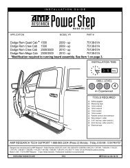
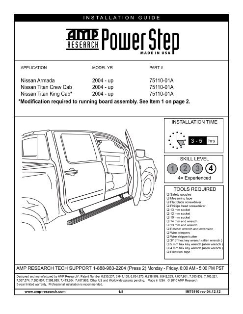
INSTALLATION GUIDE<br />
APPLICATION MODEL YR PART #<br />
Nissan Armada <strong>2004</strong> - up 75110-01A<br />
Nissan Titan Crew Cab <strong>2004</strong> - up 75110-01A<br />
Nissan Titan King Cab* <strong>2004</strong> - up 75110-01A<br />
*Modification required to running board assembly. See Item 1 on page 2.<br />
INSTALLATION TIME<br />
3 - 5 hrs<br />
SKILL LEVEL<br />
1 2 3 4<br />
4= Experienced<br />
TOOLS REQUIRED<br />
Safety goggles<br />
Measuring tape<br />
Flat blade screwdriver<br />
Phillips head screwdriver<br />
13 mm socket<br />
12 mm socket<br />
10 mm socket<br />
14 mm end wrench<br />
13 mm end wrench<br />
Ratchet wrench and extension<br />
Wire crimpers<br />
Wire stripper/cutter<br />
3/16” hex key wrench (allen wrench )<br />
5 mm hex key wrench (allen wrench )<br />
4 mm hex key wrench (allen wrench )<br />
Electrical tape<br />
AMP RESEARCH TECH SUPPORT 1-888-983-2204 (Press 2) Monday - Friday, 6:00 AM - 5:00 PM PST<br />
Designed and manufactured by AMP Research ® . Patent Number 6,830,257; 6,641,158; 6,834,875; 6,938,909; 6,942,233; 7,007,961; 7,055,839; 7,163,221;<br />
7,367,574; 7,380,807; 7,398,985; 7,413,204; 7,487,986. Other US and Worldwide patents pending. Made in USA © <strong>2010</strong> AMP Research<br />
5-year limited warranty. Professional installation is re<strong>com</strong>mended.<br />
www.amp-research.<strong>com</strong> 1/8 IM75110 rev 04.12.12
A<br />
F<br />
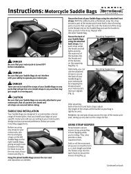
AMP RESEARCH POWER STEP – NISSAN<br />
Note: Some Applications require modification.<br />
Application<br />
Cut Length<br />
Crew Cab / Armada 72” (No Modifi cation Required)<br />
King Cab 60” (Trim 12”)<br />
Cut Dimension<br />
C E<br />
1 x2<br />
Running board assembly<br />
(A) 19-03763-90 End cap left (x1)<br />
(B) 19-03760-90 End cap right (x1)<br />
(C) 19-02663-90 T-nut insert (x2)<br />
(D) 19-02802-90 Socket cap screw (x2)<br />
(E) 19-03761-90 End cap wedge right (x1)<br />
(F) 19-03764-90 End cap wedge left (x1)<br />
B<br />
D<br />
2 x2<br />
10-03072-10<br />
Motor Linkage Assembly<br />
3<br />
x2<br />
10-03073-10<br />
Idler Linkage Assembly<br />
4<br />
19-03082-91<br />
Wire Harness<br />
5<br />
19-03297-93<br />
Controller<br />
www.amp-research.<strong>com</strong> 2/8 IM75110 rev 04.12.12<br />
6<br />
x2<br />
20-03289-92<br />
Motor
AMP RESEARCH POWER STEP – NISSAN<br />
PARTS LIST AND<br />
HARDWARE<br />
IDENTIFICATION<br />
7 x2<br />
19-03339-90<br />
Cable Tie 11”<br />
8 x4<br />
16-03014-90<br />
Washer Block<br />
9 x4<br />
19-02845-90<br />
Hex Nut<br />
10 x6<br />
19-03076-90<br />
Socket Cap Screw<br />
11<br />
x8<br />
19-02802-90<br />
Socket Cap Screw<br />
12 x4 13<br />
19-03353-90<br />
Nylock Nut<br />
x4<br />
19-03352-90<br />
Flat Head Cap Screw<br />
14 x25<br />
19-02805-90<br />
Cable Tie 7”<br />
15<br />
x4 x4 17<br />
19-03354-90<br />
Posi-Tap<br />
16<br />
19-02822-90<br />
Rivet<br />
x2<br />
19-03238-90<br />
Motor Cover<br />
www.amp-research.<strong>com</strong> 3/8 IM75110 rev 04.12.12<br />
18<br />
x2 19<br />
19-02903-90<br />
Motor Bracket<br />
x6<br />
19-02903-90<br />
Socket Cap Screw
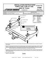
Attach the linkage assemblies with supplied hardware<br />
at the first and third set of attachment points.<br />
-<br />
The Idler linkage will be mounted in the first attachment<br />
point.<br />
8 9<br />
AMP RESEARCH POWER STEP – NISSAN<br />
Tighten bolts. Attach rear Motor linkage assembly<br />
(with large upper pivot shaft) with the same<br />
procedure.<br />
Forward mount shown<br />
3<br />
10<br />
The rear mount will have the large upper shaft<br />
1 2<br />
for the motor.<br />
After both linkage assemblies are securely<br />
mounted, attach step extrusion to lower linkage<br />
by aligning t-nuts with slots.<br />
Adjust step extrusion so that the overhang off<br />
the rear linkage is about 11.5 inches.<br />
1<br />
2<br />
3<br />
4<br />
5<br />
6 7 8 9 1 01<br />
11 112<br />
3<br />
1<br />
Tighten 4 screws with 3/16” allen wrench.<br />
1<br />
4<br />
Mount controller just rearward of air-intake box<br />
using two 11” wire ties. Attach to factory conduit<br />
running between airbox and master cylinder.<br />
7<br />
11<br />
5<br />
www.amp-research.<strong>com</strong> 4/8 IM75110 rev 04.12.12<br />
6<br />
5
AMP RESEARCH POWER STEP – NISSAN<br />
Connect Power Step wire harness to the<br />
controller. Make sure that the locking tabs<br />
engage on the connector.<br />
Route long end of harness and red and black<br />
power lines across to the other side. Secure<br />
with wire wraps along the fire wall.<br />
4<br />
4<br />
7<br />
Remove fuse. Attach eyelet of red wire to<br />
positive terminal. Attach eyelet of black wire to<br />
negative terminal of battery.<br />
4<br />
8<br />
Long end to passenger side and sho rt end to<br />
driver side, route harness under vehicle toward<br />
motors. Run trigger wires through floor board<br />
grommet behind front linkage assemblies.<br />
4<br />
Trigger Wire<br />
9<br />
Route harness back to rear linkages. Secure<br />
with wire wraps.<br />
10<br />
Insert plug from wire harness onto motor.<br />
4<br />
4<br />
11<br />
12<br />
www.amp-research.<strong>com</strong> 5/8 IM75110 rev 04.12.12<br />
6
AMP RESEARCH POWER STEP – NISSAN<br />
Slide rubber grommet on wire harness into<br />
slot of motor cover. Insert motor cover onto<br />
motor.<br />
Insert plastic push pin rivets in mounting<br />
holes of motor cover.<br />
6<br />
17<br />
17<br />
16<br />
13<br />
Install motor mounting bracket using the three<br />
M6x12 bolts. Then mount motor using the two<br />
M6x16 countersink bolts. Use thread locking<br />
<strong>com</strong>pound.<br />
14<br />
After removing sill plate from front door of vehicle,<br />
lift carpet and pull trigger wires though grommet.<br />
Remove kick panel and locate the appropriate<br />
signal wires (will match trigger wires).<br />
19<br />
13<br />
DRIVER SIDE:<br />
• Light Blue<br />
• Red w/ yellow stripe<br />
(Crew Cab and ArmadaOnly)<br />
18<br />
15 16<br />
Using supplied Posi-Tap connector, splice<br />
Power Step trigger wires into the corresponding<br />
signal wires located in step 16.<br />
17<br />
PASSENGER SIDE:<br />
• Red with Blue Stripe &<br />
Silver Dashes<br />
• Grey (Crew Cab and Armada Only)<br />
Reinstall fuse. Check that all doors activate<br />
the Power Step and the LED Lights work when<br />
doors open and close. Reinstall any remaining<br />
trim panels.<br />
4<br />
15<br />
DRIVER SIDE: • Light Blue<br />
17<br />
18<br />
www.amp-research.<strong>com</strong> 6/8 IM75110 rev 04.12.12
FINAL SYSTEM CHECK<br />
Check that all doors activate the PowerStep and the LED lights work when doors open and close.<br />
NORMAL OPERATION: When the doors open, PowerStep automatically deploys from under the vehicle.<br />
When the doors are closed, PowerStep will automatically return to the stowed/retracted position. Note that<br />
there is a 2-second delay before the PowerStep returns to the stowed/retracted position.<br />
CORRECT OPERATION OF LIGHTS: All four lamps will illuminate upon opening any door of vehicle. Lamps<br />
will stay on until restowing of both Power Steps or until 5 minutes has expired with the doors open. When the<br />
lights timeout after 5 minutes, they can be reillumintated by closing and opening any door of vehicle.<br />
www.amp-research.<strong>com</strong> 7/8 IM75110 rev 04.12.12
Congratulations on your purchase of the<br />
genuine AMP Research PowerStep!<br />
Here’s what you should know...<br />
AMP Research PowerStep running boards automatically move<br />
when the doors are opened to assist entering and exiting the vehicle.<br />
Automatic power deploy:<br />
The running boards will extend down and out when the doors are opened.<br />
Automatic power stow:<br />
The running boards will return to the stowed position when the doors are closed. There will be a 2-second<br />
delay before the running boards move to the stowed position.<br />
Automatic stop:<br />
If an object is in the way of the moving running board, the running board will automatically stop.<br />
To reset, clear any obstruction, then simply open and close the door to resume normal operation.<br />
Manually set in the deployed (OUT) position for access to the roof:<br />
your foot while at the same time closing the door. To resume normal operation, open and close the door.<br />
Maintenance: In adverse conditions, debris such as mud, dirt, and salt may be<strong>com</strong>e trapped in the running<br />
board mechanism, possibly leading to unwanted noise. If this occurs, manually set the running boards to<br />
Avoid spraying the motors directly. After washing, apply silicone spray lubricant to the hinge pivot pins.<br />
Do not apply silicone, wax or protectants like Armor All® to the running board stepping surface.<br />
Caution! Keep hands away when the running board is in motion.<br />
5-YEAR LIMITED WARRANTY<br />
AMP RESEARCH warrants this product to be free from defects in material and workmanship for FIVE (5) YEARS FROM<br />
DATE OF PURCHASE, provided there has been normal use and proper maintenance. This warranty applies to the original<br />
purchaser only. All remedies under this warranty are limited to the repair replacement of the product itself, or the repair<br />
or replacement of any <strong>com</strong>ponent part thereof, found by the factory to be defective within the time period specified. The<br />
decision to repair or replace is wholly within the discretion of the manufacturer.<br />
for instructions. You must retain proof of purchase and submit a copy with any items returned for warranty work. Upon<br />
<strong>com</strong>pletion of warranty work, if any, we will return the repaired or replaced item or items to you freight prepaid. Damage<br />
to our products caused by accidents, fire, vandalism, negligence, misinstallation, misuse, Acts of God, or by defective parts<br />
not manufactured by us, is not covered under this warranty.<br />
ANY IMPLIED WARRANTIES OF MERCHANTABILITY AND/OR FITNESS FOR A PARTICULAR PURPOSE CREATED HEREBY ARE<br />
LIMITED IN DURATION TO THE SAME DURATION AND SCOPE AS THE EXPRESS WRITTEN WARRANTY. OUR COMPANY SHALL<br />
NOT BE LIABLE FOR ANY INCIDENTAL OR CONSEQUENTIAL DAMAGE.<br />
Some states do not allow limitations on how long an implied warranty lasts, or the exclusion or limitation of incidental<br />
or consequential damages, so the above limitations or exclusions may not apply to you. This warranty gives you specific<br />
legal rights, and you may also have other rights that vary from state to state.<br />
FOR WARRANTY ISSUES WITH THIS PRODUCT PLEASE CALL AMP RESEARCH CUSTOMER SERVICE 1-800-315-9697<br />
WARNING<br />
Be sure to read and precisely follow the provided instructions when installing this product. Failure to do so could place the vehicle<br />
occupants in a potentially dangerous situation. After installing or reinstalling, re-check to insure that the product is properly installed.