Installation Instructions - AutoAccessoriesGarage.com
Installation Instructions - AutoAccessoriesGarage.com
Installation Instructions - AutoAccessoriesGarage.com

Create successful ePaper yourself
Turn your PDF publications into a flip-book with our unique Google optimized e-Paper software.
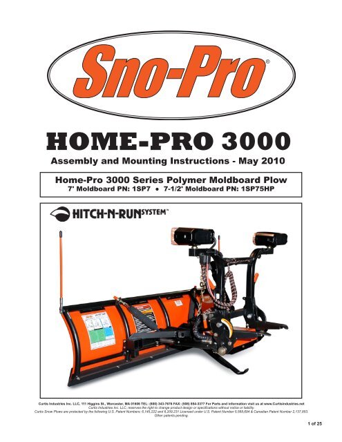
HOME-PRO 3000Assembly and Mounting <strong>Instructions</strong> - May 2010Home-Pro 3000 Series Polymer Moldboard Plow7' Moldboard PN: 1SP7 ● 7-1/2' Moldboard PN: 1SP75HPCurtis Industries Inc. LLC, 111 Higgins St., Worcester, MA 01606 TEL: (800) 343-7676 FAX: (508) 854-3377 For Parts and information visit us at www.Curtisindustries.netCurtis Industries Inc. LLC, reserves the right to change product design or specifications without notice or liability.Curtis Snow Plows are protected by the following U.S. Patent Numbers: 6,145,222 and 6,209,231 Licensed under U.S. Patent Number 5,568,694 & Canadian Patent Number 2,137,853.Other patents pending.1 of 25
Curtis Plows are simple by design. Our unit utilizes an A-Frame assembly for mounting the Electric/Hydraulic unit.This exclusive Curtis feature eliminates the need for Hydraulic Quick-disconnects and also "Hides-Away"our Power unit. Our A-Frame assembly takes the weight of the Power unit off the Lift Frame assembly and allows forincreased airflow to the Radiator. Curtis uses State of the Art techniques for fit and consistency such as an AutomatedConveyor System, Robotic Welding, High Definition Plasma and Hydraulic Press Brakes.We feel these techniques are very important for overall quality and serviceability.To help our customers understand the loads being imposed on their vehicles as well as the importance of ballast insome applications, we also incorporate <strong>com</strong>puter modeled weight distributions. Some vehicles may require "HelperSprings", "Air Shocks" or similar devices to <strong>com</strong>pensate for the added weight of the Plow equipment.This information is available upon request. From all of us at Curtis, Thank you for choosing our products!IMPORTANT: Before you Start...► Install any additional required equipment first, such as Snow tires, Helper Springs, Lights, etc.► Read and understand this manual before beginning Plow assembly.► Check Carton contents prior to beginning Plow assembly.► Work in an organized area large enough to pull vehicle up to Plow for final attachment.► Have your tools ready prior to assembly, it will speed up the assembly time.CAUTION1. Always disconnect vehicle battery when working with vehicle-side wiring.2. Plow assembly requires handling of many heavy parts. Be sure to handlewith care. Use proper tooling, equipment and assistance where indicated.Required Tools■ 1/2" Drive Ratchet■ 3/8" Drive Ratchet■ 15/16" Deep Socket & Wrench■ 3/4" Socket & Wrench■ 5/8" Wrench■ 9/16" Socket■ 9/16" Wrench (2)■ 1/2" Socket & Wrench■ Pliers or Vice-GripsContent Checklist for 2 Cartons:Plow Package #1:● Trip Frame (1TBP22C)● Lift Frame Assembly (1TBP38D)Plow Package #2:● A-Frame Assembly with Angle Pistons● Light Kit (set of 2) (1TBP39H)● Hardware Box #1● Hardware Box #2● Truck-Side Harness with Plug Storage Holder● Blade Markers (set of 2) (1TBP37)Shipped with Cartons:● Moldboard <strong>com</strong>plete with Cutting Edge■ Wire Cutters■ Hammer or Mallet■ 10" or 12" Adjustable Wrench■ 1-1/8" Open End Wrench■ Low Temperature Grease2 of 25
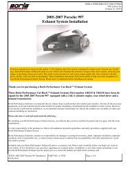
Home-Pro 3000 Illustrated Parts List - Moldboard & Trip Frame53 4126138991112107Moldboard/Trip Frame Parts ListRef # Item # Item Description Qty.1 1TBP21I 7' HOME-PRO MOLDBOARD 12 1TBP21K 7.5' HOME-PRO MOLDBOARD 13 1TBP124 HOME-PRO MOLDBOARD SKIN HMW PLASTIC - 7' 14 1TBP124-90HP HOME-PRO MOLDBOARD SKIN HMW PLASTIC - 7.5' 15 1TBP37 BLADE MARKER 26 1TBP34 SPRING EYEBOLT 5/8"-11 X 7 27 BUY LOCALLY 3/16" X 2" COTTER PIN 28 1TBP22C TRIP FRAME ASSEMBLY (HOME-PRO) 19 1TBP23 1" X 4" CLEVIS PIN 210 1TBP127 TRIP FRAME PIVOT PIN HOME-PRO 3000 (3-7/8" LONG) 111 1TBP49I 7' CUTTING EDGE 112 1TBP49K 7-1/2' CUTTING EDGE 113 1TBP33 TRIP SPRING 23 of 25
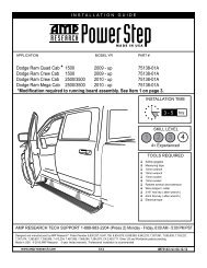
Home-Pro 3000 Illustrated Parts List - A-Frame & Harness2 3PLOW SIDETRUCK SIDEApply Grease1028 2214114Apply Grease10141115 68122415926251617131819Inside A-Frame29202330217274 of 25
Home-Pro 3000 Illustrated Parts List - A-Frame & HarnessA-Frame/Harness Parts ListRef # Item # Item Description Qty.1TBP29C A-FRAME ASSEMBLY COMPLETE 11 8SV-NAFW-B5 A-FRAME ASSEMBLY - FRAME ONLY 12 1TBP58A A-FRAME COVER, SnoPro 3000 13 1TBP30 5/16" x 24" CHAIN 14 1TBP31 5/16" ANCHOR SHACKLE 15 1TBP100 A-FRAME JACK SWITCH 16 1TBP100A TOGGLE SWITCH BOOT 17 1TBP106 JACK LEG 18 1TBP128 A-FRAME HOSE GROMMET 39 1TBP129 HARNESS (SPIRAL) WRAP, 16" LENGTH 1101112131TBP27 10" ANGLE PISTON 21TBP73 1" x 3" CLEVIS PIN 21UHJA JACK ADAPTER 3000 SERIES (HYD JACK ONLY) 11TBP98F 90 DEG. BRASS BAR STREET ELBOW 114 1TBP98G 90 DEGREE ELBOW 215 1UHP UNIVERSAL HARNESS-PLOW SIDE 116 1UHT UNIVERSAL HARNESS-TRUCK SIDE 117 1TBP95 3" JACK CYLINDER 118 1TBP96 6" JACK SPRING 119 1TBP111 JACK SPRING GUIDE ROD 120 BUY LOCALLY 5/8"-11 x 4-1/2" GRADE 5 HEX BOLT 121 BUY LOCALLY 5/8"-11 NYLON LOCKNUT 122 1TBP48A LIGHT SWITCH FOR TRUCK PLOW 123 1TBP62 #4 CABLE 90" 124 1TBP136 VEHICLE SIDE CONTROL WEATHER CAP 125 1TBP140 LOCK PIN STORAGE HOLDER & LANYARD 126 1TBP141 HARNESS LOCK PIN (SET OF 5) 127 1TBP54 HI-AMP WEATHER CAP 128 1TBP61A 12V MOTOR SOLENOID 129 8SV-TBP117-B5 A-FRAME BOTTOM JACK COVER 130 1TBP53 HI-AMP BATTERY HARNESS 15 of 25
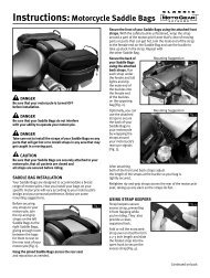
Home-Pro 3000 Illustrated Parts List - Lift Frame1381415191781618711129222024635WARNING12101216 of 25
Home-Pro 3000 Illustrated Parts List - Lift FrameLift Frame Parts ListRef # Item # Item Description Qty.1TBP38D LIFT FRAME HOME PRO 7' & 7.5' COMPLETE 11 8SV-TBP114A-B5 DRIVER'S SIDE LATCH HOOK HOME-PRO 12 8SV-TBP115A-B5 PASSENGER'S SIDE LATCH HOOK HOME-PRO 13 1TBP107 SNAP LOCK HANDLE (INCLUDED IN 9SV-SLH KIT) 24 1TBP33B SNAP LOCK SPRING (INCLUDED IN 9SV-SLH KIT) 25 1TBP103 PLASTIC HANDLE FOR SNAP LOCK SP3000 (INCLUDED IN 9SV-SLH KIT) 26 1TBP112A LIFT FRAME SIDE PLATE, LH SNO-PRO 3000 (INCLUDED IN 8SV-TBP112-B5 KIT) 17 1TBP112B LIFT FRAME SIDE PLATE, RH SNO-PRO 3000 (INCLUDED IN 8SV-TBP112-B5 KIT) 18 1TBP39H PLOW LIGHT KIT, DUAL HALOGEN LAMPS W/SWITCH KIT (2 HEAD LAMPS) 19 1TBP161 PLOW LIGHT MOUNTING HARDWARE 110 1TBP33A-1 TORSION SPRING, LH SNO-PRO 3000 (INCLUDED IN 9SV-TBP33A KIT) 111 1TBP33A-2 TORSION SPRING, RH SNO-PRO 3000 (INCLUDED IN 9SV-TBP33A KIT) 112 1TBP113 TORSION SPRING BUSHING (INCLUDED IN 9SV-TBP33A KIT) 213 1TBP40 LIFT ARM 114 1TBP108 1" x 4-1/2" CLEVIS PIN 115 1TBP42 3/4" x 4-1/2" CLEVIS PIN 116 1TBP43 3/4" x 2-3/4" CLEVIS PIN 117 1TBP44A 7-1/2" LIFT PISTON 118 1TBP98H 45 DEGREE ELBOW FOR LIFT PISTON 119 1TBP109 1" PISTON SPACER 220211TBP135 PLUG STORAGE HOLDER 11TBP159 SNAP LOCK CROSS BOLT WITH BUSHING AND NUT 222 1TBP97 PLASTIC HANDLE COVER (NOT ORDERABLE) 2ORDERABLE AS KITS - NOT SEPARATELYRef 3,4,5 # 9SV-SLH SNAP LOCK HANDLE KIT (KIT INCLUDES 2 HANDLES, 2 SPRINGS, 2 HANDLE COVERS) 16,7 8SV-TBP112-B5 LIFT FRAME SIDE PLATE KIT, SNO-PRO 3000, (KIT INCLUDES L&R PLATES) 110,11,12 9SV-TBP33A TORSION SPRING KIT (SIDE PLATE TORSION SPRINGS & BUSHINGS, SET OF 2) 17 of 25
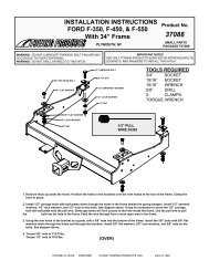
Home-Pro 3000 Illustrated Parts List - Hydraulics1723255292KTI Hydraulics - Aluminum End Head253964344401244238419 8 10 11SPX Hydraulics2136OLDSTYLE30NEWSTYLE31252735 23132326142819173719181616233433 24OLDERMODELS ONLY322021228 of 25
Home-Pro 3000 Assembly <strong>Instructions</strong>Figure 4. Connect Angle Ram Cylinders to Trip Frame1" x 4" Clevis Pin1" x 4" Clevis PinSwing A-Frame L&Rto insert Pins3/16" x 2"Cotter PinSection 4. Lift Frame Side Plate InstallA.) Locate both L&R Lift Frame Side Plates (1TBP112A&B) and slide (1) onto each side of the A-FrameHinge Pin. Figure 5.B.) Slide the L&R Torsion Springs (1TBP33A-1 & 1TBP33A-2) over Hinge Pins with the 90º bent endsinside the hole in the Spring Keeper on the corresponding Side Plate. The straight Spring Legs shouldbe resting on the A-Frame Spring Stop. Refer to Figures 5 on the next page & Figure 8 on page 15.C.) Install Torsion Spring Bushings (1TBP113) through the Torsion Springs and over the Hinge Pins.Fasten loosely with (1) 1/2"-13 x 1" Patch Bolt and 1/2" Flat Washer threaded into each Hinge Pin tosecure the assemblies. Do Not tighten Bolts at this time. Repeat procedure on opposite side.D.) Using the A-Frame as a lever, grasp the A-Frame near the Side Plates at the top of the assembly andpull back, raising the Moldboard to the vertical position.E.) Secure one end link of the Lift Chain to the middle hole in the Chain Bracket on the A-Frameusing (1) 5/16" Chain Shackle supplied in Plow Hardware Bag. See Figure 6.NOTEThe 3 mounting holes are used to fine-tune the attachment and liftingperformance of the Plow on a specific vehicle. The middle hole is a goodstarting point.F.) Install (1) Blade Marker at each end of Moldboard Top Tube using hardware supplied with BladeMarkers. Figure 6.12 of 25
Home-Pro 3000 Assembly <strong>Instructions</strong>Figure 5. Lift Frame Side Plate <strong>Installation</strong>Torsion Springand BushingRightLift FrameSide PlateLeftLift FrameSide PlateTorsion Springand BushingFigure 6. Attach Lift Chain and Mount Blade MarkersChain ShackleMount Blade MarkersCotter Pin13 of 25
Home-Pro 3000 Assembly <strong>Instructions</strong>Section 5. Mount Lift Frame to A-Frame Side PlatesA.) With assistance, position Lift Frame to Side Plates and mount with (4) 5/8"-18 x 1-3/4" Bolts and5/8"-18 Lock Nuts. To provide proper clearance, 5/8" Bolts must be installed from the inside of LiftFrame with Lock Nuts located on the outside of Lift Frame. This is necessary to provide properclearance. Tighten 5/8" Gr.8 fasteners mounting the Lift Frame to 225 ft./lbs., then fully tighten thePatch Bolts retaining the Side Plates to 55 ft/lbs. Refer to Figures 7 & 8.NOTEThe Side Plates have (3) sets of holes that can be used for mounting the Lift Frame.Refer to Page 19 for information on determining hole locations.Installing the Lift Frame in the incorrect holes will affect the attachment andremoval of the Plow to the vehicle.ADDITIONALNOTESWhen setting up the Plow for the first time, adjust the Plow Chain so that the LiftFrame Attaching Forks are parallel to the A-Frame. Once Plow is set-up correctly,index the Chain for future reference. Due to variations from truck to truck, onelink adjustments may be necessary to fine tune the individual Plow to a specificvehicle.Figure 7. Mount Lift Frame to A-Frame Side Plates2-PERSON LIFTLift FrameAlign on both sides of Lift Frameand secure with 5/8" BoltsAlign on both sidesof Lift Frame and securewith 5/8" Bolts14 of 25
Home-Pro 3000 Assembly <strong>Instructions</strong>Figure 8. Lift Frame Mounting Reference ViewLeft Side Shown5/8" Locknuts installedon Outside of Lift FrameSpring Keeper on Side PlateTorsion SpringLift Frame Side PlateA-Frame Spring StopTorsion Spring Bushing1/2" Patch BoltSection 6. Lift Frame SetupA.) Mount Lift Arm (1TBP40) to Upper Mounting Tabs of Lift Frame as shown in Figure 9A. Lift Armmounts with (1) 3/4" x 4-1/2" Clevis Pin (1TBP42) and is secured with a 2" Cotter Pin.B.) Locate Lift Cylinder (1TBP44A) and mount to front of Lift Arm with 1" Piston Spacers (1TBP109).The 1" x 4-1/2" Clevis Pin (1TBP108) will pass through the Piston Spacers and Lift Cylinder and will besecured with a 2" Cotter Pin. As shown in Figure 9A.NOTEThe Hose Port on the Lift Cylinder must face towards the Driver’s Side.C.) With top of Lift Cylinder secured, raise the Lift Arm and swing the Lift Cylinder bottom betweenLower Mounting Tabs on the Lift Frame and secure with a 3/4" x 2-3/4" Clevis Pin (1TBP43) and a2" Cotter Pin to secure the Clevis Pin. Figure 9B.D.) The Hydraulic Hose should now be connected to the 45º Elbow. Use (2) 9/16" Wrenches when tighteningLift Hose to avoid twisting the Hose.E.) Mount Lights to Lift Frame using supplied hardware (1TBP161) and Harness Plug Storage Holder(1TBP135). See Figure 10.15 of 25
Home-Pro 3000 Assembly <strong>Instructions</strong>Figure 9. Lift Arm MountingA3/4" x 4-1/2"Clevis PinB1" x 4-1/2"Clevis PinSecurewith Cotter Pin3/4" x 2-3/4"Clevis PinInsert Clevis Pinthrough 1" PistonSpacers when mountingLift CylinderCotter PinPoint Hose Port toward A-FrameInsert Cylinder Endthrough Lift Frame Tabsand secure with Cotter PinFigure 10. Headlight MountingMetal Adjustment CupRubber Vibration MountThreaded InsertHarness PlugStorage Holderon Driver’s Sideas shown16 of 25
Home-Pro 3000 Assembly <strong>Instructions</strong>Section 7. Harness StepsA.) If Harness and Lift Cylinder Hose are not pre-wrapped together with Hose Wrapping, tie togetherusing (3) Wire Ties 4" apart starting at the A-Frame exit.B.) Secure the Harness to the Lift Frame using supplied Harness Clips, Bolts, Nuts and Wire Ties.C.) Attach Plow Harness to Lift Frame at Tab 'A' using supplied P-Clamp. Route Plow Harness in frontof Lift Frame Up Left tube (Driver’s side) and attach Harness to Tab 'B' using supplied P-Clamp.Tab 'B' has 3 mounting holes to allow proper Harness reach for different height trucks. If the Plow isassembled in the bottom set of Side Plate mounting holes, use the bottom hole in Tab 'B'.See Figures 11 & 12.Figure 11. Secure Harness to Lift FrameConnect Headlightsto Harness then secureconnected Plugs with Cable-TiesTab 'A'with ClampLoop and secureexcess HeadlightCable with Cable-TiesTab 'B'with ClampLift HoseCAUTIONRouting of Harness and location of each Harness Clip & Wire Tie is veryimportant so that it will 'flex' properly when the Plow is lowered or raised.Failure to correctly route and secure Harness may result in severe damage.D.) Plug the Plow Light Connectors into Harness and secure the connected Plugs to the Lift Frame.Excess Cord from Lights can be secured with Tie-Wraps where shown. Figure 11.17 of 25
Home-Pro 3000 Assembly <strong>Instructions</strong>Figure 12. Secure Harness to Lift FrameFront Left (Driver's Side) of Lift FrameHarness Routes behind1/4" Bolt & Lock NutHarness Clipon Tab 'B'To Lift Cylinder1/4" Bolt & Lock NutHarness Clipon Tab 'A'Up to LightsHarness ClipsCAUTIONAfter securing Harness, with Main Plug stored in Plug Storage Holder, it is importantto move Driver's Side Latch Hook through its cycle of motion by hand to ensureclearance between Harness and any moving parts. Failure to properly secureHarness could result in severe damage to the Harness.18 of 25
Home-Pro 3000 Assembly <strong>Instructions</strong>Figure 13. Determine X Height for Correct Side Plate Mounting HolesXSection 8. X Height ProcedureA.) Install Mount Kit on vehicle referring to Mount Kit installation procedure. Wire vehicle referring toPage 22 for detailed Harness & Control System installation information.B.) With vehicle parked on level ground and properly ballasted for snow plow use, measure the distancefrom the ground up to the centerline of the Latch Bar on the Receiver as shown.C.) Once 'X' dimension is measured, use the Application Chart below to determine which hole locationsto use when attaching the Lift Frame to the Side Plates.NOTEThis is a general guideline to help make the assembly process easier.Due to great variations in suspension, tires, age of the vehicle, etc. it may benecessary to change the Side Plate positions after Plow is attached to the vehicle.Figure 14. Select Appropriate Side Plate Mounting HolesTopCenterBottomInsert Spring Endinto KeeperTopCenterIf X is 16-3/4" and above use Top HolesIf X is between 15-3/4" to 16-1/2" use Center HolesBottomIf X is below 15-1/2" use Bottom Holes19 of 25
Home-Pro 3000 Assembly <strong>Instructions</strong>Vehicle to Plow Initial SetupOnce Vehicle Mount Kit and Harness installations are <strong>com</strong>plete, raise the Plow to the same level as theMount Kit Receiver. To ac<strong>com</strong>plish this, drive truck close to Plow and attach the Harness Plug. Put 'In-Cab' Control System into the 'float' position and raise the Plow using the A-Frame Jack Switch to align therear of the Lift Frame with the Mount Kit Receiver. If necessary, readjust the Side Plate positions.Jack Adjustment ProcedureWith the Lift Cylinder & Jack fully retracted, top off the Pump Reservoir. It may be necessary to run theJack for 10 cycles as a break-in period. During the break-in period, check that the Jack retracts fullyagainst the Pan of the A-Frame. If the Jack Leg doesn’t fully retract, remove the A-Frame Cover andmanually adjust the tension on the Jack Leg Return Spring using a 1-1/8" open end wrench. The JackReturn Spring is located forward of the Pump in the A-Frame Pump cavity. See Figure 15 below.A 3/4" Hex Nut holds the tension on the Spring. If more tension is required, tighten the Hex Nut against theSpring. When adjusting the Spring tension, use full turn increments and test the function of the Jack Leg aftereach turn of the Hex Nut. Do not over tighten the Return Spring.Figure 15. Jack Spring AdjustmentA-Frame with Cover removed3/4" Hex Nut to adjust Jack SpringJack Switch20 of 25
Home-Pro 3000 Assembly <strong>Instructions</strong>Figure 17. Home Pro 3000 Harness LayoutRef.: this is for old styleharness p/n 1TBP134(pre-2009 version)Relay for 2009-NOTE: allvalve coilshave oneorange(ground)wire.22 of 25
Home-Pro 3000 Assembly <strong>Instructions</strong>Figure 18. Home Pro 3000 Control Detail23 of 25
Home-Pro 3000 Assembly <strong>Instructions</strong>Section 10. Snow Plow StorageA.) When Plow is disconnected, coat all exposed chrome rods on both Angle Ram Cylinders and Lift Cylinderwith Light Grease. The Grease will keep exterior surfaces free from rust and corrosion.B.) Whenever Moldboard is disconnected, coat the exposed chrome rods of both Angle Ram Cylinders withLight Grease to protect them from rust and corrosion.C.) Coat all Pivot Pins and other wear points with Chassis Lubricant.D.) Unplug all electrical connections. Coat all connections with a dielectric <strong>com</strong>pound to prevent corrosion andplug into their corresponding weather plugs. Unplug the Plow Lights and use a dielectric <strong>com</strong>pound atLight connections to prevent corrosion.25 of 25
SNO-PRO ® 30002004 – Ford F-150 4 x 4(With Snow Plow Prep. Package ONLY)Vehicle Mounting Kit: 1FK26Revised 14 February 2011Curtis Industries Inc. LLC, 111 Higgins St., Worcester, MA 01606 TEL: (800) 343-7676 FAX: (508) 854-3377 For Parts and information visit us at www.Curtisindustries.netCurtis Industries Inc. LLC, reserves the right to change product design or specifications without notice or liability.Curtis Snow Plows are protected by the following U.S. Patent Numbers: 6,145,222 and 6,209,231 Licensed under U.S. Patent Number 5,568,694 & Canadian Patent Number 2,137,853.Other patents pending.1 of 4
1FK26 Vehicle Mount Kit Parts ListItem # Description Qty.1 Mounting Frame Weldment 12 1/2" x 2-3/8" Pipe Spacer with Handle 23 5/8" x 2-5/16" Pipe Spacer 2Hardware Bag Components Included In This Kit4 1/2"-13 x 5" Bolt, Gr. 5, Cad., Plated 25 5/8"-11 x 5-1/2" Bolt, Gr. 5, Cad., Plated 26 1/2" Flat Washer, Cad., Plated 27 1/2" Lock Washer, Cad., Plated 28 1/2"-13 Hex Nut, Cad., Plated 29 5/8" Flat Washer, Cad., Plated 210 5/8" Lock Washer, Cad., Plated 211 5/8"-11 Hex Nut, Cad., Plated 2Hardware Components Included In Plow Kit1a Plug Mount Bracket 1- 10-32 x 3/4" Hex Head Screw, Plated 2- 10-32 Nylock Lock Nut, Plated 2- 8-32 x 1" Hex Head Screw, Plated 1- 8-32 Nylock Lock Nut, Plated 1- #8 Nylon Flat Washer, 3/4" O.D. 1- #8 Flat Washer, SAE, Plated 1WARNINGIt is highly re<strong>com</strong>mended that front “helper springs”, “airshocks”,or other similar devices be installed onto this vehicle to prevent thefront suspension from “bottoming out” while carrying a snow plow.Vehicle must be properly "ballasted" by placing ballast weight behind the centerlineof Rear Axle so that no more than 62% of the total weight of the Vehicle, Snow Plow,Driver, Ballast weight, (and any cargo) is placed on the Front Axle while at the same timenot exceeding the Gross Vehicle Weight Rating and Front or Rear Gross Axle Weight Ratings.2 of 4
1FK26 Mounting23Cut out 32" section as shown6487OriginalBolting Bar9511110To Bolting BarOriginal TowHook Bolts1aCurtis Industries, LLC. reserves the right to change product design or specifications without notice or liability.Curtis Snow Plows and Truck equipment should only be used on vehicles equipped with the manufacturer’s Snow Plow preparation package.Snow Plowing without the original snow plow preparation package may damage your vehicle and the added weight of the equipment mayimpair the operation and control of the vehicle.3 of 4
1FK26: 2004- Ford F-150 4x4Mounting Kit <strong>Installation</strong> <strong>Instructions</strong>1. VEHICLE PREPARATION(1a.) Remove and store the vehicle (front) tow hooks. Leave thethreaded tow hook bolting bars in place inside the framerails and save the tow hook bolts. The tow hook bolts andbolting bars will be reused to install the plow mountingframe (1). The tow hooks will not be reinstalled with themounting frame (1) in place.(1b.) Trim out a piece of the lower plastic section of the frontbumper 32" long and up even with the lower rear steelflange of the bumper.4. FINAL ADJUSTMENT AND INSPECTIONBend over the ends of the handles on the pipe spacers(with handles) (2) that protrude from the slotted hole in eachframe rail. Return the tow hooks with the vehicle so they canbe reinstalled if the mounting frame is removed. Inspect themounting frame (1) attachment bolts to be certain that theyare all in place and that they are all tight.NOTEAll fasteners should remain loose or"finger tight" until all <strong>com</strong>ponents havebeen attached to Vehicle or installationinstructions specify tightening.2. MOUNTING FRAME(2a.) Lift the mounting frame (1) up under the front of the vehiclewith the vertical side plates between the inner walls of theframe rails and with the horizontal bolting plates against thebottom walls of the frame rails. Line up the holes in thehorizontal bolting plates of the mounting frame (1) with thetow hook bolt holes in the frame rails. Fasten loosely usingthe original equipment tow hook bolts threaded into thebolting bars inside the frame rails.(2b.) Place a 5/8" flat washer (9) and pipe spacer (3) onto eachof the 5/8"-13 x 5-1/2" bolts (5) then insert through the largehole in the outer wall of each frame rail just behind thebumper mounting flange continue through the inner wallswith the threaded ends of the bolts through the front holein each vertical side plate of the mounting frame (1).Fasten each side loosely using a 5/8" lock washer (10) and5/8"-13 nut (11).(2c.) Place a pipe spacer (with handle) (2) into each frame railthrough the large slotted hole under the radiator web/bodymount bracket on the outer walls of the rails. Place a 1/2"flat washer (6) onto each of the ½”-13 x 5” bolts (4) andinsert each through the square hole in the outer wall of eachframe rail just below the large slotted hole that the pipespacers (with handle) (2) were placed into. Continueinserting the 1/2"-13 x 5" bolts (4) through the pipe spacers(with handle) (2), and the square hole in the inner walls ofthe frame rails with the threaded ends through the rearholes in the vertical side plates of the mounting frame (1).Fasten each side loosely using 1/2" lock washers (7) and1/2"-13 nuts (8).3. TIGHTENINGMake certain that the pipe spacers (3) are positionedcorrectly through the holes in both the inner and outer wallsof each frame rail, then tighten the original equipment towhook bolts installed through the horizontal bolting platesof the mounting frame (1). Tighten the remaining 1/2" and5/8" fasteners holding the mounting frame (1) to the framerails.The frame rail can be crushed whiletightening the 1/2" and 5/8" fasteners if theIMPORTANTpipe spacers (2) (3) are not installed or areinstalled improperly.4 of 4