EMC Student Wiring Guide - the Georgia Agriculture Curriculum ...
EMC Student Wiring Guide - the Georgia Agriculture Curriculum ...
EMC Student Wiring Guide - the Georgia Agriculture Curriculum ...

Create successful ePaper yourself
Turn your PDF publications into a flip-book with our unique Google optimized e-Paper software.
<strong>Student</strong> <strong>Guide</strong><br />
to<br />
<strong>Wiring</strong><br />
2008 Edition<br />
Brought to you by<br />
<strong>Georgia</strong> <strong>EMC</strong><br />
2100 East Exchange Place<br />
Tucker, GA 30084<br />
(770) 270-6950<br />
www.georgiaemc.com
GEORGIA ELECTRIC MEMBERSHIP CORPORATION<br />
MARKETING, MEMBER SERVICES AND COMMUNICATIONS ASSOCIATION<br />
FOREWORD<br />
The electric membership cooperatives (<strong>EMC</strong>s) of<br />
<strong>Georgia</strong> assembled this booklet as a training guide to<br />
promote standard wiring requirements. This booklet is<br />
comprised of sections of <strong>the</strong> National Electrical Code<br />
(NEC). It is intended as a training guide for students to<br />
be used in a supervised classroom environment that does<br />
not have access to <strong>the</strong> official NEC standards. The NEC<br />
references in this booklet may not be in <strong>the</strong>ir entirety.<br />
Refer to <strong>the</strong> 2008 edition of <strong>the</strong> NEC for complete text.<br />
This booklet is a NOT-FOR-SALE item, intended to<br />
be provided to all users free of charge. This booklet<br />
should only be used as a wiring guideline and does not<br />
supersede any National Electrical Codes, <strong>EMC</strong> special<br />
wiring requirements, or any o<strong>the</strong>r authority having<br />
jurisdiction. Any consumer or licensed electrician<br />
planning to do electrical work should contact <strong>the</strong>ir local<br />
authorities for approval of <strong>the</strong>ir work.<br />
i<br />
This booklet is intended to be used as a resource in<br />
preparation for <strong>the</strong> <strong>EMC</strong>/FFA <strong>Wiring</strong> Contest (Career<br />
Development Event). The annual contest is sponsored by<br />
<strong>the</strong> electric cooperatives in cooperation with <strong>the</strong> FFA. The<br />
purpose of <strong>the</strong> contest is to promote and expand<br />
educational programs in electrification for students of<br />
agricultural education. The electric membership<br />
corporations throughout <strong>Georgia</strong> sponsor <strong>the</strong>se activities<br />
as a means of promoting education in <strong>the</strong> safe, efficient<br />
use of electrical energy.<br />
Participants in <strong>the</strong> contest are students in grades 9-12<br />
enrolled in agricultural education and active members of<br />
<strong>the</strong> <strong>Georgia</strong> FFA. <strong>Student</strong>s compete first in area contests;<br />
<strong>the</strong> top two contestants from each area move on to <strong>the</strong><br />
state competition held each year at <strong>the</strong> FFA/FCCLA<br />
Center in Covington. Scholarships awarded to area and<br />
state winners can be used at college or vocational schools.<br />
For more information on this program, contact <strong>the</strong><br />
Member Services department at your local electric<br />
cooperative, speak with an FFA advisor, contact<br />
<strong>Georgia</strong> <strong>EMC</strong> at 1-800-544-4362, or go to<br />
www.gaaged.org or www.georgiaemc.com.<br />
revised August 2008
ii<br />
Table of Contents<br />
1 GENERAL . . . . . . . . . . . . . . . . . . . . . . . . . . . . . . . . . . . . . . . . . .Page<br />
1.1 through 1-10 General <strong>Wiring</strong> Statements . . . . . . . . . . . . . . . . . . . . 1<br />
2 DEFINITIONS<br />
2.1 through 2-39 Electrical Terms, Devices, Materials & Equipment<br />
Defined . . . . . . . . . . . . . . . . . . . . . . . . . . . . . . . . . . . . . . . . . . . . . . 2<br />
3 SERVICE ENTRANCES<br />
3.1 Point of Attachment . . . . . . . . . . . . . . . . . . . . . . . . . . . . . . . . . . . . 6<br />
3.2 Vertical Clearance for Overhead Service Conductors . . . . . . . . . . . 7<br />
3.3 Service Drop Attachment . . . . . . . . . . . . . . . . . . . . . . . . . . . . . . . . 7<br />
3.4 Underground Service . . . . . . . . . . . . . . . . . . . . . . . . . . . . . . . . . . . 8<br />
3.5 Residential Service Requirements . . . . . . . . . . . . . . . . . . . . . . . . . . 8<br />
3.6 Conduit . . . . . . . . . . . . . . . . . . . . . . . . . . . . . . . . . . . . . . . . . . . . . . 8<br />
3.7 Conductors . . . . . . . . . . . . . . . . . . . . . . . . . . . . . . . . . . . . . . . . . . . 9<br />
3.8 Meter Base . . . . . . . . . . . . . . . . . . . . . . . . . . . . . . . . . . . . . . . . . . 10<br />
4 GROUNDING<br />
4.1 Service Grounding Wire . . . . . . . . . . . . . . . . . . . . . . . . . . . . . . . . 11<br />
4.2 Safety Bonding . . . . . . . . . . . . . . . . . . . . . . . . . . . . . . . . . . . . . . . 11<br />
4.3 Equipment Grounding . . . . . . . . . . . . . . . . . . . . . . . . . . . . . . . . . . 12<br />
4.4 Grounding Electrode . . . . . . . . . . . . . . . . . . . . . . . . . . . . . . . . . . . 13<br />
5 PROTECTIVE EQUIPMENT<br />
5.1 Approval . . . . . . . . . . . . . . . . . . . . . . . . . . . . . . . . . . . . . . . . . . . . 14<br />
5.2 Location . . . . . . . . . . . . . . . . . . . . . . . . . . . . . . . . . . . . . . . . . . . . 14<br />
5.3 Mounting of Equipment . . . . . . . . . . . . . . . . . . . . . . . . . . . . . . . . 15<br />
5.4 Marking of Equipment . . . . . . . . . . . . . . . . . . . . . . . . . . . . . . . . . 15<br />
5.5 Overcurrent Protection . . . . . . . . . . . . . . . . . . . . . . . . . . . . . . . . . 16<br />
6 BRANCH CIRCUIT WIRING<br />
6.1 Length of Free Conductors . . . . . . . . . . . . . . . . . . . . . . . . . . . . . . 17<br />
6.2 Mechanical and Electrical Conductor Continuity . . . . . . . . . . . . . 17<br />
6.3 Splices . . . . . . . . . . . . . . . . . . . . . . . . . . . . . . . . . . . . . . . . . . . . . . 17<br />
6.4 Circuit Identification . . . . . . . . . . . . . . . . . . . . . . . . . . . . . . . . . . . 18<br />
6.5 Cable Clamps and Connectors . . . . . . . . . . . . . . . . . . . . . . . . . . . 18<br />
6.6 Non-Metallic-Shea<strong>the</strong>d Cable . . . . . . . . . . . . . . . . . . . . . . . . . . . . 18<br />
6.7 Knockout Closers . . . . . . . . . . . . . . . . . . . . . . . . . . . . . . . . . . . . . 19<br />
6.8 General Purpose Outlets . . . . . . . . . . . . . . . . . . . . . . . . . . . . . . . . 19<br />
6.9 Small Appliance Circuits . . . . . . . . . . . . . . . . . . . . . . . . . . . . . . . 19<br />
6.10 Dwelling Unit Receptacle Outlets . . . . . . . . . . . . . . . . . . . . . . . . . 20<br />
6.11 Ground Fault Interrupter Protection . . . . . . . . . . . . . . . . . . . . . . . 25<br />
6.12 Arc-Fault Circuit Interrupter Protection . . . . . . . . . . . . . . . . . . . . 27<br />
6.13 Boxes . . . . . . . . . . . . . . . . . . . . . . . . . . . . . . . . . . . . . . . . . . . . . . 27<br />
6.14 Number of Conductors . . . . . . . . . . . . . . . . . . . . . . . . . . . . . . . . . 27<br />
6.15 Conduit . . . . . . . . . . . . . . . . . . . . . . . . . . . . . . . . . . . . . . . . . . . . . 32<br />
7 LIGHT CIRCUIT WIRING<br />
7.1 Lighting Outlets Required . . . . . . . . . . . . . . . . . . . . . . . . . . . . . . . 33<br />
7.2 Switches . . . . . . . . . . . . . . . . . . . . . . . . . . . . . . . . . . . . . . . . . . . . .33<br />
7.3 Installation . . . . . . . . . . . . . . . . . . . . . . . . . . . . . . . . . . . . . . . . . . .34<br />
7.4 Reidentification of Conductors . . . . . . . . . . . . . . . . . . . . . . . . . . .34<br />
7.5 Fixtures in Clo<strong>the</strong>s Closets . . . . . . . . . . . . . . . . . . . . . . . . . . . . . . 35<br />
7.6 Cove Lighting . . . . . . . . . . . . . . . . . . . . . . . . . . . . . . . . . . . . . . . . 36<br />
7.7 Clearance and Installation . . . . . . . . . . . . . . . . . . . . . . . . . . . . . . . 36<br />
7.8 Adjacent Combustible Materials . . . . . . . . . . . . . . . . . . . . . . . . . . 36<br />
8 CONDUCTOR SIZING BASED ON VOLTAGE DROP<br />
8.1 Branch Circuit Conductor Sizing . . . . . . . . . . . . . . . . . . . . . . . . . 36<br />
9 COOKING APPLIANCES<br />
9.1 Installation . . . . . . . . . . . . . . . . . . . . . . . . . . . . . . . . . . . . . . . . . . 36<br />
10 WATER HEATER WIRING<br />
10.1 Installation . . . . . . . . . . . . . . . . . . . . . . . . . . . . . . . . . . . . . . . . . . 37<br />
11 CLOTHES DRYER WIRING<br />
11.1 Receptacle . . . . . . . . . . . . . . . . . . . . . . . . . . . . . . . . . . . . . . . . . . . 38<br />
11.2 Wire Sizes for Circuit . . . . . . . . . . . . . . . . . . . . . . . . . . . . . . . . . . 38<br />
11.3 Bonding . . . . . . . . . . . . . . . . . . . . . . . . . . . . . . . . . . . . . . . . . . . . 38<br />
12 ELECTRICAL MOTORS<br />
12.1 Installation and Location . . . . . . . . . . . . . . . . . . . . . . . . . . . . . . . . 38<br />
12.2 Rating . . . . . . . . . . . . . . . . . . . . . . . . . . . . . . . . . . . . . . . . . . . . . . 38<br />
12.3 Devices O<strong>the</strong>r Than Fuses . . . . . . . . . . . . . . . . . . . . . . . . . . . . . . 38<br />
13 ELECTRIC SPACE HEAT WIRING<br />
13.1 General . . . . . . . . . . . . . . . . . . . . . . . . . . . . . . . . . . . . . . . . . . . . . 39<br />
13.2 Wire Sizing for Resistance Heating . . . . . . . . . . . . . . . . . . . . . . . 39<br />
13.3 Portable Heater Receptacles . . . . . . . . . . . . . . . . . . . . . . . . . . . . . 39<br />
13.4 Derating of Conductors . . . . . . . . . . . . . . . . . . . . . . . . . . . . . . . . . 39<br />
13.5 Thermostats . . . . . . . . . . . . . . . . . . . . . . . . . . . . . . . . . . . . . . . . . . 40<br />
13.6 Branch Circuits . . . . . . . . . . . . . . . . . . . . . . . . . . . . . . . . . . . . . . .40<br />
14 CENTRAL SPACE HEATING AND AIR CONDITIONING EQUIPMENT<br />
14.1 General . . . . . . . . . . . . . . . . . . . . . . . . . . . . . . . . . . . . . . . . . . . . . 41<br />
14.2 Location and Clearance . . . . . . . . . . . . . . . . . . . . . . . . . . . . . . . . . 41<br />
14.3 Disconnecting Means . . . . . . . . . . . . . . . . . . . . . . . . . . . . . . . . . . 41<br />
14.4 Overcurrent Protection . . . . . . . . . . . . . . . . . . . . . . . . . . . . . . . . . 42<br />
14.5 Circuit Capacity . . . . . . . . . . . . . . . . . . . . . . . . . . . . . . . . . . . . . . .42<br />
14.6 Low Voltage Control <strong>Wiring</strong> . . . . . . . . . . . . . . . . . . . . . . . . . . . . . 42<br />
15 AGRICULTURAL BUILDING<br />
15.1 Scope . . . . . . . . . . . . . . . . . . . . . . . . . . . . . . . . . . . . . . . . . . . . . . 43<br />
15.2 Definitions . . . . . . . . . . . . . . . . . . . . . . . . . . . . . . . . . . . . . . . . . . 43<br />
15.3 O<strong>the</strong>r Articles . . . . . . . . . . . . . . . . . . . . . . . . . . . . . . . . . . . . . . . . 43<br />
15.4 Surface Temperatures . . . . . . . . . . . . . . . . . . . . . . . . . . . . . . . . . . 44<br />
15.5 <strong>Wiring</strong> Methods . . . . . . . . . . . . . . . . . . . . . . . . . . . . . . . . . . . . . . 44<br />
iii
15.6 Switches, Receptacles, etc. . . . . . . . . . . . . . . . . . . . . . . . . . . . . . . 45<br />
15.7 Motors . . . . . . . . . . . . . . . . . . . . . . . . . . . . . . . . . . . . . . . . . . . . . 45<br />
15.8 Luminaires (Lighting Fixtures) . . . . . . . . . . . . . . . . . . . . . . . . . . . 45<br />
15.9 Electrical Supply from a Distribution Point . . . . . . . . . . . . . . . . . 46<br />
15.10 Equipotential Planes and Bonding of . . . . . . . . . . . . . . . . . . . . . . .48<br />
16 MOBILE HOMES (NEC 550)<br />
16.1 Definitions . . . . . . . . . . . . . . . . . . . . . . . . . . . . . . . . . . . . . . . . . . 48<br />
16.2 Mobile Home Services . . . . . . . . . . . . . . . . . . . . . . . . . . . . . . . . . 49<br />
16.3 Grounding . . . . . . . . . . . . . . . . . . . . . . . . . . . . . . . . . . . . . . . . . . 50<br />
1. GENERAL<br />
1.1 The latest issue of <strong>the</strong> National Electrical Code (NEC) (2008<br />
edition) as published by <strong>the</strong> National Fire Protection Association<br />
(NFPA), along with OSHA Rules and Regulations on Electrical<br />
Construction, is used as a wiring guide to assure a safe and<br />
adequate electrical installation.<br />
1.2 Workmanship: Electrical equipment shall be installed in a neat and<br />
workmanlike manner. OSHA<br />
iv<br />
17 OUTSIDE WIRING<br />
17.1 Installation . . . . . . . . . . . . . . . . . . . . . . . . . . . . . . . . . . . . . . . . . . 52<br />
18 UNDERGROUND WIRING<br />
18-1 Underground Feeder . . . . . . . . . . . . . . . . . . . . . . . . . . . . . . . . . . 52<br />
TABLES<br />
NEC Table 310.15(B)(6) – Sizing Service Entrance Cable . . . . . . . . . . . 10<br />
NEC Table 250.66 – Grounding Electrode Conductor . . . . . . . . . . . . . . 12<br />
NEC Table 314.16(A) - Metal Boxes . . . . . . . . . . . . . . . . . . . . . . . . . . . 29<br />
NEC Table 314.16(B) - Volume Required per Conductor . . . . . . . . . . . . 29<br />
NEC Table 310.16 - Allowable Ampacities of Conductors . . . . . . . . . . . 54<br />
NEC Table C.1 - Conductors in Conduit . . . . . . . . . . . . . . . . . . . . . . . . .62<br />
NFEC Table 8 - Single Phase Motor Currents . . . . . . . . . . . . . . . . . . . . .63<br />
NFEC Table 16 - Conductor Sizing . . . . . . . . . . . . . . . . . . . . . . . . . . . . .64<br />
1.3 Conductors normally used to carry current shall be of copper unless<br />
o<strong>the</strong>rwise provided in <strong>the</strong> NEC. Where <strong>the</strong> conductor material is not<br />
specified, <strong>the</strong> sizes given in <strong>the</strong> NEC shall apply to copper<br />
conductors. Where o<strong>the</strong>r materials are used, <strong>the</strong> size shall be<br />
changed accordingly. NEC 110.5<br />
1.4 Switches or circuit breakers shall not disconnect <strong>the</strong> grounded<br />
conductor of a circuit. NEC 404.2(B)<br />
1.5 General use switches and circuit breakers shall clearly indicate<br />
whe<strong>the</strong>r <strong>the</strong>y are in <strong>the</strong> open (off) or closed (on) position. Where<br />
<strong>the</strong>se switch or circuit breaker handles are operated vertically, <strong>the</strong><br />
up position of <strong>the</strong> handle shall be <strong>the</strong> "on" position. Exception:<br />
Vertically operated double-throw switches shall be permitted to be<br />
in <strong>the</strong> closed (on) position with <strong>the</strong> handle in ei<strong>the</strong>r <strong>the</strong> up or down<br />
position. NEC 404.7<br />
1<br />
DIAGRAMS<br />
NEC Exhibit 100.6 - Feeder and Branch Circuits . . . . . . . . . . . . . . . . . . . 3<br />
NEC Exhibit 230.22 - Clearances for Overhead Services . . . . . . . . . . . . . .7<br />
Rooftop Clearances for Overhead Service . . . . . . . . . . . . . . . . . . . . . . . . . 8<br />
Underground Meter Installation . . . . . . . . . . . . . . . . . . . . . . . . . . . . . . . . 10<br />
Method for determining # of Receptacles per Branch Circuit . . . . . . . . . 19<br />
NEC Exhibit 210.24 – Wall Spacing of Receptacles . . . . . . . . . . . . . . . . 21<br />
NEC Exhibit 210.25 – Small-Appliance Branch Circuits . . . . . . . . . . . . 22<br />
NEC Exhibit 210.26 – Receptacle Spacing in Countertops . . . . . . . . . . . 23<br />
NEC Exhibit 210.9 – GFCI-Protection in Bathrooms . . . . . . . . . . . . . . . 24<br />
<strong>EMC</strong> Diagram 1 - Spring-Type Grounding Strap . . . . . . . . . . . . . . . . . . 30<br />
<strong>EMC</strong> Diagram 2 - Double Throw Switch Installation . . . . . . . . . . . . . . . 55<br />
EXAMPLES<br />
Derating Conductor Load . . . . . . . . . . . . . . . . . . . . . . . . . . . . . . . . . . . . 40<br />
Residential <strong>Wiring</strong> Calculations . . . . . . . . . . . . . . . . . . . . . . . . . . . . . . . 56<br />
GEORGIA’S ELECTRIC COOPERATIVES<br />
Alphabetical List of <strong>EMC</strong>s . . . . . . . . . . . . . . . . . . . . . . . . .inside front cover<br />
List of <strong>EMC</strong>s by location . . . . . . . . . . . . . . . . . . . . . . . . .inside back cover<br />
Map of <strong>EMC</strong> locations . . . . . . . . . . . . . . . . . . . . . . . . . . . . . . . .back cover<br />
1.6 Conductors with white or gray insulation or insulation with three<br />
continuous white stripes on o<strong>the</strong>r than green insulation shall be<br />
used as <strong>the</strong> grounded conductor in <strong>the</strong> circuit. NEC 200.7(A) When<br />
using three conductor SE cable, <strong>the</strong> bare conductor shall be used as<br />
<strong>the</strong> grounded conductor. NEC 230.41<br />
1.7 If a conductor with insulation that is white or gray or that has three<br />
continuous white stripes is used for o<strong>the</strong>r than a grounded<br />
conductor, <strong>the</strong> insulation must be reidentified at its termination and<br />
at each location where <strong>the</strong> conductor is visible and accessible.<br />
NEC 200.7(C)<br />
1.8 On outlets requiring a grounded conductor, <strong>the</strong> grounded conductor<br />
shall be attached to <strong>the</strong> terminal that is substantially white (silver)<br />
in color. NEC 200.10(B)<br />
1.9 Reference sources identified by initials in paren<strong>the</strong>ses at <strong>the</strong> end of<br />
a paragraph and in table and diagram headings are as follows:<br />
NEC National Electrical Code<br />
OSHA Occupational Safety and Health Administration<br />
REA Rural Electrification Administration<br />
NFEC National Food and Energy Council<br />
NFPA National Fire Protection Association
1.10 The licensed electrician, contractor, or consumer planning a wiring<br />
installation should contact <strong>the</strong> local authority for any interpretations<br />
or modifications of <strong>the</strong>se <strong>Wiring</strong> Rules.<br />
2. DEFINITIONS (NEC Article 100)<br />
2.1 ACCESSIBLE: (As applied to equipment) Admitting close<br />
approach; not guarded by locked doors, elevation or o<strong>the</strong>r effective<br />
means.<br />
2.2 ACCESSIBLE: (As applied to wiring methods) Capable of being<br />
removed or exposed without damaging <strong>the</strong> building structure or<br />
finish, or not permanently closed in by <strong>the</strong> structure or finish of <strong>the</strong><br />
building.<br />
2.3 ACCESSIBLE, READILY: (Readily accessible) Capable of being<br />
reached quickly for operation, renewal, or inspections, without<br />
requiring those to whom ready access is requisite to climb over or<br />
remove obstacles or to resort to portable ladders, chairs, etc.<br />
energy to one or more outlets to which appliances are to be<br />
connected; such circuits to have no permanently connected lighting<br />
fixtures not a part of an appliance. Appliance branch circuits for a<br />
kitchen, pantry, etc. and for laundry areas are not permitted to have<br />
any o<strong>the</strong>r outlets or permanently connected lighting fixtures<br />
connected to <strong>the</strong>m.<br />
2.10 BRANCH CIRCUIT, GENERAL PURPOSE: A branch circuit that<br />
supplies two or more receptacles or outlets for lighting and<br />
appliances.<br />
2.11 BRANCH CIRCUIT, INDIVIDUAL: A branch circuit that supplies<br />
only one utilization equipment. An individual branch circuit shall be<br />
permitted to supply any load for which it is rated: for example, one<br />
range, or one space heater, or one motor. NEC 210-23 A branch<br />
circuit may be installed to supply one duplex receptacle, which can<br />
accommodate two cord-connected and plug-connected appliances or<br />
similar equipment. This circuit would not be considered an<br />
individual branch circuit.<br />
2<br />
2.4 AMPACITY: The current in amperes a conductor can carry<br />
continuously under <strong>the</strong> conditions of use without exceeding its<br />
temperature rating.<br />
2.5 APPLIANCE: An appliance is utilization equipment, generally<br />
o<strong>the</strong>r than industrial, normally built in standardized sizes or types,<br />
which is installed or connected as a unit to perform one or more<br />
functions such as clo<strong>the</strong>s washing, air conditioning, food mixing,<br />
deep frying, etc.<br />
2.12 BRANCH CIRCUIT, MULTIWIRE: A branch circuit that consists<br />
of two or more ungrounded conductors that have a voltage between<br />
<strong>the</strong>m, and a grounded conductor that has equal voltage between it<br />
and each ungrounded conductor of <strong>the</strong> circuit and that is connected<br />
to <strong>the</strong> neutral or grounded conductor of <strong>the</strong> system.<br />
3<br />
2.6 APPROVED: Acceptable to <strong>the</strong> authority having jurisdiction. The<br />
phrase “authority having jurisdiction” is used in NFPA documents<br />
in a broad manner since jurisdictions and “approval” agencies vary,<br />
as do <strong>the</strong>ir responsibilities. Where public safety is primary, <strong>the</strong><br />
“authority having jurisdiction” may be a federal, state, local, or<br />
o<strong>the</strong>r regional department or individual such as a fire chief; fire<br />
marshal; chief of a fire prevention bureau, labor department or<br />
health department; building official; electrical inspector; or o<strong>the</strong>rs<br />
having statutory authority. For insurance purposes, an insurance<br />
inspection department, rating bureau, or o<strong>the</strong>r insurance company<br />
representative may be <strong>the</strong> “authority having jurisdiction.” In many<br />
circumstances, <strong>the</strong> property owner or <strong>the</strong> owner’s designated agent<br />
assumes <strong>the</strong> role of <strong>the</strong> “authority having jurisdiction;” at<br />
government installations, <strong>the</strong> commanding officer or departmental<br />
official may be <strong>the</strong> “authority having jurisdiction.”<br />
2.7 AUTOMATIC: Self-acting, operating by its own mechanism when<br />
actuated by some impersonal influence, as for example, a change in<br />
current, pressure, temperature, or mechanical configuration.<br />
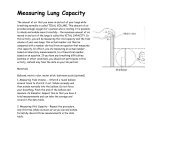
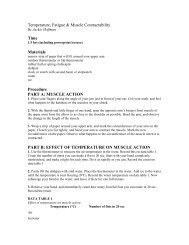
2.13<br />
NEC Exhibit 100.6 Feeder and Branch Circuits<br />
CIRCUIT BREAKER: A device designed to open and close a<br />
circuit by nonautomatic means and to open <strong>the</strong> circuit automatically<br />
on a predetermined overcurrent without damage to itself when<br />
properly applied within its rating.<br />
2.8 BRANCH CIRCUIT: The circuit conductors between <strong>the</strong> final overcurrent<br />
device protecting <strong>the</strong> circuit and <strong>the</strong> outlet(s).<br />
2.9 BRANCH CIRCUIT, APPLIANCE: A branch circuit supplying<br />
2.14 CONCEALED: Rendered inaccessible by <strong>the</strong> structure or finish of<br />
<strong>the</strong> building. Wires in concealed raceways are considered
concealed, even though <strong>the</strong>y may become accessible by<br />
withdrawing <strong>the</strong>m.<br />
2.15 CONTINUOUS LOAD: A load where <strong>the</strong> maximum current is<br />
expected to continue for three hours or more.<br />
2.16 CONTROLLER: A device or group of devices that serves to<br />
govern, in some predetermined manner, <strong>the</strong> electrical power<br />
delivered to <strong>the</strong> apparatus to which it is connected.<br />
2.17 DEVICE: A unit of an electric system that is intended to carry or<br />
control, but not utilize, electrical energy. Units, such as switches,<br />
circuit breakers, fuse holders, receptacles, attachment plugs, and<br />
lamp holders that distribute or control but do not consume<br />
electricity are termed “devices.”<br />
2.18 DISCONNECTING MEANS: A device, group of devices, or o<strong>the</strong>r<br />
means by which <strong>the</strong> conductors of a circuit can be disconnected<br />
from <strong>the</strong>ir source of supply.<br />
2.25 GROUNDING CONDUCTOR: A conductor used to connect<br />
equipment or <strong>the</strong> grounded circuit of a wiring system to a<br />
grounding electrode or electrodes.<br />
2.26 GROUNDING CONDUCTOR, EQUIPMENT: The conductive path<br />
installed to connect normally non-current-carrying metal parts of<br />
equipment toge<strong>the</strong>r and to <strong>the</strong> system grounded conductor or to <strong>the</strong><br />
grounding electrode conductor, or both.<br />
2.27 IDENTIFIED: (As applied to equipment) Recognizable as suitable<br />
for <strong>the</strong> specific purpose, function, use, environment, application,<br />
etc., where described in a particular Code requirement.<br />
2.28 LOCATION:<br />
1. Damp Location: Partially protected locations under canopies,<br />
marquees, roofed open porches, and like locations, and interior<br />
locations subject to moderate degrees of moisture, such as some<br />
basements, some barns and some cold-storage warehouses.<br />
4<br />
2.19 DWELLING:<br />
1. Dwelling Unit: A single unit, providing complete and independent<br />
living facilities for one or more persons, including permanent<br />
provisions for living, sleeping, cooking and sanitation.<br />
2. One Family Dwelling: A building consisting solely of one<br />
dwelling unit.<br />
3. Two Family Dwelling: A building consisting solely of two<br />
dwelling units.<br />
4. Multifamily Dwelling: A building containing three or more dwelling<br />
units.<br />
2.20 ENCLOSED: Surrounded by a case, housing, fence, or walls that<br />
prevents persons from accidentally contacting energized parts.<br />
2.21 EQUIPMENT: A general term including material, fittings, devices,<br />
appliances, luminaries (fixtures), apparatus, machinery, and <strong>the</strong> like<br />
used as a part of, or in connection with, an electrical installation.<br />
2.22 EXPOSED: (As applied to wiring methods) On or attached to <strong>the</strong><br />
surface or behind panels designed to allow access.<br />
2. Dry Location: A location not normally subject to dampness or<br />
wetness. A location classified as dry may be temporarily subject to<br />
dampness or wetness, as in <strong>the</strong> case of a building under<br />
construction.<br />
3. Wet Location: Installations underground or in concrete slabs or<br />
masonry in direct contact with <strong>the</strong> earth; and locations subject to<br />
saturation with water or o<strong>the</strong>r liquids, such as vehicle washing<br />
areas; and locations exposed to wea<strong>the</strong>r and unprotected.<br />
2.29 OUTLET: A point on <strong>the</strong> wiring system at which current is taken to<br />
supply utilization equipment.<br />
2.30 RACEWAY: An enclosed channel designed expressly for holding<br />
wires, cables, or bus bars, with additional functions as permitted in<br />
<strong>the</strong> NEC.<br />
Raceways may be of metal or nonmetallic materials. Raceways<br />
include, but are not limited to, rigid metal conduit, rigid<br />
nonmetallic conduit, intermediate metal conduit, liquid tight<br />
flexible conduit, flexible metallic tubing, flexible metal conduit,<br />
electrical nonmetallic tubing, electrical metallic tubing, under floor<br />
raceways, cellular concrete floor raceways, cellular metal floor<br />
raceways, surface raceways, wireways, and busways.<br />
5<br />
2.23 FEEDER: All circuit conductors between <strong>the</strong> service equipment,<br />
<strong>the</strong> source of a separately derived system, or o<strong>the</strong>r power supply<br />
source and <strong>the</strong> final branch-circuit overcorrect device.<br />
2.31 RAINTIGHT: Constructed or protected so that exposure to a<br />
beating rain will not result in <strong>the</strong> entrance of water under specified<br />
test conditions.<br />
2.24 GROUNDED CONDUCTOR: A system or circuit conductor that<br />
is intentionally grounded.<br />
2.32 RECEPTACLE: A receptacle is a contact device installed at <strong>the</strong><br />
outlet for <strong>the</strong> connection of an attachment plug.
2.33 SERVICE DROP: The overhead service conductors from <strong>the</strong> last<br />
pole or o<strong>the</strong>r aerial support to and including <strong>the</strong> splices, if any,<br />
connecting to <strong>the</strong> service-entrance conductors at <strong>the</strong> building or<br />
o<strong>the</strong>r structure.<br />
2.34 SERVICE-ENTRANCE CONDUCTORS, OVERHEAD SYSTEM:<br />
The service conductors between <strong>the</strong> terminals of <strong>the</strong> service<br />
equipment and a point usually outside <strong>the</strong> building, clear of<br />
building walls, where joined by tap or splice to <strong>the</strong> service drop.<br />
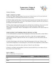
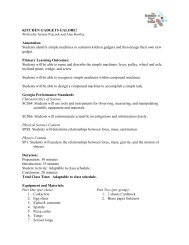
3.2 VERTICAL CLEARANCE FOR OVERHEAD SERVICE<br />
CONDUCTORS: The vertical clearance of <strong>the</strong> conductor above <strong>the</strong><br />
roof level shall be maintained for a distance of not less than 3 feet<br />
(900 mm) in all directions from <strong>the</strong> edge of <strong>the</strong> roof. NEC<br />
230.24(A)<br />
Service-drop conductors, where not in excess of 600 volts, nominal,<br />
shall have <strong>the</strong> following minimum clearance from final grade:<br />
NEC 230.24(B)<br />
6<br />
2.35 SERVICE-ENTRANCE CONDUCTORS, UNDERGROUND<br />
SYSTEM: The service conductors between <strong>the</strong> terminals of <strong>the</strong><br />
service equipment and <strong>the</strong> point of connection to <strong>the</strong> service lateral.<br />
Where service equipment is located outside <strong>the</strong> building walls, <strong>the</strong>re<br />
may be no service entrance conductors, or <strong>the</strong>y may be entirely<br />
outside <strong>the</strong> building.<br />
2.36 SERVICE EQUIPMENT: The necessary equipment, usually<br />
consisting of a circuit breaker or switch and fuses, and <strong>the</strong>ir<br />
accessories, connected to <strong>the</strong> load end of service conductors to a<br />
building or o<strong>the</strong>r structure, or an o<strong>the</strong>rwise designated area, and<br />
intended to constitute <strong>the</strong> main control and cutoff of <strong>the</strong> supply.<br />
2.37 SPECIAL PERMISSION: The written consent of <strong>the</strong> authority<br />
having jurisdiction.<br />
2.38 SWITCHES:<br />
1. General-Use Switch: A switch intended for use in general<br />
distribution and branch circuits. It is rated in amperes, and it is<br />
capable of interrupting its rated current at its rated voltage.<br />
2. Motor-Circuit Switch: A switch, rated in horsepower, capable of<br />
interrupting <strong>the</strong> maximum operating overload current of a motor of<br />
<strong>the</strong> same horsepower rating as <strong>the</strong> switch at <strong>the</strong> rated voltage.<br />
3.2.1 Ten feet (3.0 m) at <strong>the</strong> electric service entrance to buildings, also at<br />
<strong>the</strong> lowest point of <strong>the</strong> drip loop of <strong>the</strong> building electric entrance,<br />
and above areas or sidewalks accessible only to pedestrians,<br />
measured from final grade or o<strong>the</strong>r accessible surface only for<br />
service-drop cables supported on and cabled toge<strong>the</strong>r with a<br />
grounded bare messenger where <strong>the</strong> voltage does not exceed<br />
150 volts to ground.<br />
3.2.2 Twelve feet (3.7 m) over residential property and driveways, and<br />
those commercial areas not subject to truck traffic where <strong>the</strong><br />
voltage does not exceed 300 volts to ground.<br />
3.2.3 Fifteen feet (4.5 m) for those areas listed in <strong>the</strong> 12 ft. (3.7 m)<br />
classification where <strong>the</strong> voltage exceeds 300 volts to ground.<br />
3.2.4 Eighteen feet (5.5 m) over public streets, alleys, roads, parking<br />
areas subject to truck traffic, driveways on o<strong>the</strong>r than residential<br />
property, and o<strong>the</strong>r land such as cultivated, grazing, forest, and<br />
orchard.<br />
15 ft<br />
(over 300V to<br />
ground<br />
7<br />
2.39 WEATHERPROOF: Constructed or protected so that exposure to<br />
<strong>the</strong> wea<strong>the</strong>r will not interfere with successful operation. Rainproof,<br />
rain tight, or watertight equipment can fulfill <strong>the</strong> requirements for<br />
wea<strong>the</strong>rproof where varying wea<strong>the</strong>r conditions o<strong>the</strong>r than wetness,<br />
such as snow, ice, dust, or temperature extremes, are not a factor.<br />
3. SERVICE ENTRANCES<br />
3.1 POINT OF ATTACHMENT: The point of attachment of <strong>the</strong> service<br />
drop conductors to a building or o<strong>the</strong>r structure shall provide <strong>the</strong><br />
minimum clearances as specified in NEC 230.9 and 230.24. In no<br />
case shall this point of attachment be less than 3.0 m (10 ft.) above<br />
finished grade NEC 230.26. The means of attachment NEC 230.27<br />
will be via fittings identified for use with service conductors.<br />
.<br />
NEC Exhibit 230.22 Clearances for overhead services<br />
3.3 SERVICE DROP ATTACHMENT: The point of attachment of <strong>the</strong><br />
service-drop conductors to a building or o<strong>the</strong>r structure shall<br />
provide <strong>the</strong> minimum clearances as specified in 3.2 of this booklet
8<br />
and NEC 230.9 and 230.24.. In no case shall this point of attachment<br />
be less than 10 ft (3.0m) above finished grade. NEC 230.26<br />
3.4 UNDERGROUND SERVICE: Contact your local electric<br />
authority office for <strong>the</strong> latest Underground Service Policy Rules<br />
and Regulations.<br />
3.5 RESIDENTIAL SERVICE REQUIREMENTS:<br />
NUMBER OF SERVICES: A building or o<strong>the</strong>r structure served<br />
shall be supplied by only one service unless permitted in NEC<br />
230.2(A) through (D).<br />
NOTE: The National Electric Code permits a separate service for<br />
each occupancy in multiple-occupancy buildings, provided <strong>the</strong><br />
service-entrance conductors are installed outside of <strong>the</strong> building, or<br />
o<strong>the</strong>r structure in accordance with NEC 230.6. Many electric power<br />
companies have specifications and have adopted special regulations<br />
covering certain types of electrical loads and service equipment that<br />
may be energized from <strong>the</strong>ir lines. It is advisable to consult with <strong>the</strong><br />
serving authority to determine line capacities before designing<br />
electrical services for large buildings.<br />
3.6.2 For all services extending through <strong>the</strong> roof, a minimum of 2 inches<br />
(50.8 mm) rigid galvanized steel conduit or intermediate metal<br />
conduit is required for mechanical strength in order to support<br />
service drop.<br />
3.6.3 The use of electrical metallic tubing (EMT) shall be permitted for<br />
both exposed and concealed work. Electrical metallic tubing shall<br />
not be used: (1) Where, during installation or afterward, it will be<br />
subject to severe physical damage; (2) Where protected from<br />
corrosion solely by enamel; (3) In cinder concrete or cinder fill<br />
where subject to permanent moisture unless protected on all sides<br />
by a layer of non-cinder concrete at least 2 inches (50 mm) thick or<br />
unless <strong>the</strong> tubing is at least 18 inches (450 mm) under <strong>the</strong> fill.<br />
Where practicable, dissimilar metals in contact anywhere in <strong>the</strong><br />
system shall be avoided to eliminate <strong>the</strong> possibility of galvanic<br />
action. NEC 358.10 and 358.12<br />
3.6.4 Ferrous or non-ferrous electric metallic tubing, elbows, couplings,<br />
and fittings shall be permitted to be installed in concrete, in direct<br />
contact with <strong>the</strong> earth, or in areas subject to severe corrosive<br />
influences where protected by corrosion protection or judged<br />
suitable for <strong>the</strong> condition. NEC 358.10(B)<br />
9<br />
3.6.5 Where a conduit enters a box, fitting, or o<strong>the</strong>r enclosure, a bushing<br />
shall be provided to protect <strong>the</strong> wire from abrasion unless <strong>the</strong><br />
design of <strong>the</strong> box, fitting, or enclosure is such as to afford<br />
equivalent protection. NEC 342.46<br />
3.7 CONDUCTORS:<br />
3.7.1 Clearance From Building Openings:<br />
Service conductors installed as open conductors or multi-conductor<br />
cable without an overall outer jacket shall have a clearance of not<br />
less than 3 feet (900 mm) from windows that are design to be<br />
opened, doors, porches, balconies, ladders, stairs, fire escapes or<br />
similar locations. NEC 230.9(A)<br />
Service conductors run above <strong>the</strong> top level of a window shall be<br />
permitted to be less than <strong>the</strong> 3 feet (900 mm) requirement above.<br />
NEC 230.9 (Exception A)<br />
Rooftop Clearances for Overhead Services<br />
3.6 CONDUIT:<br />
3.6.1 When a service mast is used for <strong>the</strong> support of service-drop<br />
conductors, it shall be of adequate strength or be supported by<br />
braces or guys to withstand safely <strong>the</strong> strain imposed by <strong>the</strong> service<br />
drop. Where raceway-type service masts are used, all raceway<br />
fittings shall be identified for use with service masts. Only power<br />
service-drop conductors shall be permitted to be attached to a<br />
service mast. NEC 230.28<br />
Overhead service conductors shall not be installed beneath openings<br />
through which materials may be moved, such as openings in farm<br />
and commercial buildings, and shall not be installed where <strong>the</strong>y<br />
obstruct entrance to <strong>the</strong>se building openings.<br />
NEC 230.9(C)<br />
3.7.2 Service entrance cable type SE may be installed for any residential<br />
installation up to and including 200 ampacity, unless prohibited by<br />
local (city or county) authority.<br />
3.7.3 Refer to table 310.16, section 18 for nonresidential (see page 49).
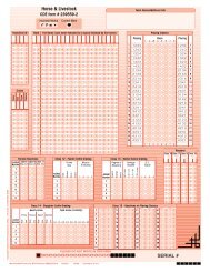
Conductor Types and Sizes for 120/240 volts,<br />
3 wire single phase dwelling<br />
NEC Table 310.15(B)(6)<br />
3.8.4 Meter base for potential (PT) or current transformer (CT) metering<br />
will be supplied by <strong>the</strong> utility, but <strong>the</strong> use of equipment must be<br />
approved before <strong>the</strong> installation.<br />
10<br />
Copper Aluminum and Rating in<br />
Copper-Clad AL<br />
Service Amps<br />
AWG<br />
AWG<br />
4 2 100<br />
3 1 110<br />
2 1/0 125<br />
1 2/0 150<br />
1/0 3/0 175<br />
2/0 4/0 200<br />
3/0 250 kcmil 225<br />
4/0 300 kcmil 250<br />
250 kcmil 350 kcmil 300<br />
350 kcmil 500 kcmil 350<br />
400 kcmil 600 kcmil 400<br />
3.8.5 Contact your local utility prior to electrical construction as<br />
<strong>the</strong>se electrical requirements may vary according to <strong>the</strong> local<br />
authority.<br />
4. GROUNDING<br />
4.1 SERVICE GROUNDING WIRE:<br />
4.1.1 Size of Alternating Current Grounding Electrode Conductor: The<br />
size of <strong>the</strong> grounding electrode conductor of a grounded or<br />
ungrounded AC system shall not be less than given in Table 250.66,<br />
except as permitted in NEC 250.66(A) through (C).<br />
4.1.2 Connections to Concrete-Encased Electrodes: Where <strong>the</strong> grounding<br />
electrode is connected to a concrete-encased electrode as permitted<br />
in NEC 250.52(A)(3), that portion of <strong>the</strong> conductor that is <strong>the</strong> sole<br />
connection to <strong>the</strong> grounding electrode shall not be required to be<br />
larger than 4AWG copper wire. NEC 250.66(B)<br />
11<br />
4.1.3 Connections to Ground Rings: Where <strong>the</strong> grounding electrode<br />
conductor is connected to a ground ring as permitted in 250.52(4),<br />
that portion of <strong>the</strong> conductor that is <strong>the</strong> sole connection to <strong>the</strong><br />
grounding electrode shall not be required to be larger than <strong>the</strong><br />
conductor used for <strong>the</strong> ground ring. NEC 250.66(C)<br />
4.1.4 Grounding electrode conductor shall be installed as specified in<br />
NEC 250.64(A) through (F): Bare alum. or copper-clad alum.<br />
grounding conductors shall not be used in direct contact with<br />
masonry or earth where subject to corrosive conditions, and where<br />
used outside <strong>the</strong>se conductors shall not be terminated within 18 in.<br />
of <strong>the</strong> earth. The grounding electrode shall be securely fastened to<br />
<strong>the</strong> surface on which it is carried. The grounding electrode shall be<br />
continuous, unless spliced by irreversible compression-type<br />
connectors.<br />
3.8 METER BASE:<br />
3.8.1 Meters, meter sockets, or meter disconnect switches nominally rated<br />
not in excess of 600 volts shall be permitted to be connected to <strong>the</strong><br />
supply side of <strong>the</strong> service disconnecting means. NEC 230.82(2),(3)<br />
3.8.2 Meter base installed on a masonry wall shall be of <strong>the</strong> type<br />
approved for this purpose.<br />
Exception: Bus bars shall be permitted to connect toge<strong>the</strong>r to form<br />
a grounding electrode. Metal enclosures for grounding electrode<br />
conductors shall be electrically continuous and securely fastened to<br />
ground clamp or fitting. The grounding electrode conductor can run<br />
to any convenient ground electrode or to each individually. The<br />
grounding electrode conductor shall be sized for <strong>the</strong> largest<br />
grounding electrode conductor among all <strong>the</strong> electrodes connected<br />
to it. To provide protection from physical damage, grounding<br />
electrode conductors smaller than 6 AWG shall be installed in<br />
conduit.<br />
3.8.3 Meter base installed for an underground service shall be of <strong>the</strong> type<br />
approved for this purpose.<br />
4.2 SAFETY BONDING: FPN: Bonding all piping and metal air ducts<br />
within <strong>the</strong> premises will provide additional safety. NEC 250.104(B)
12<br />
Table 250-66. Grounding Electrode Conductor for Alternating-Current<br />
Systems<br />
Size of Largest Ungrounded<br />
Service-Entrance Conductor or<br />
Equivalent Area for Parallel<br />
Conductors (AWG/kcmil)<br />
Copper<br />
Aluminum or<br />
Copper-Clad<br />
Aluminum<br />
2 or smaller 1/0 or smaller 8 6<br />
1 or 1/0 2/0 or 3/0 6 4<br />
2/0 or 3/0 4/0 or 250 kcmil 4 2<br />
Over 3/0 Over 250 kcmil 2 1/0<br />
through 350<br />
kcmil<br />
through 500<br />
kcmil<br />
Over 350 kcmil Over 500 kcmil 1/0 3/0<br />
through 600<br />
kcmil<br />
through 900<br />
kcmil<br />
Over 600 kcmil Over 900 kcmil 2/0 4/0<br />
through 1100 through 1750<br />
kcmil<br />
kcmil<br />
4.3 EQUIPMENT GROUNDING:<br />
Size of Grounding Electrode<br />
Conductor (AWG/kcmil)<br />
Copper<br />
Aluminum or<br />
Copper-Clad<br />
Aluminum<br />
Over 1100 Over 1750 3/0 250 kcmil<br />
kcmil<br />
kcmil<br />
4.3.1 Metal raceways, cable trays, cable armor, cable sheath, enclosures,<br />
frames, fittings and o<strong>the</strong>r metal non-current-carrying parts that are<br />
to serve as grounding conductors with or without <strong>the</strong> use of<br />
supplementary equipment grounding conductors shall be effectively<br />
bonded where necessary to assure electrical continuity and <strong>the</strong><br />
capacity to conduct safely any fault current likely to be imposed on<br />
<strong>the</strong>m. Any nonconductive paint, enamel, or similar coating shall be<br />
removed at threads, contact points, and contact surfaces or be<br />
connected by means of fittings so designed as to make such<br />
removal unnecessary. NEC 250.96<br />
cover combination are listed as providing satisfactory ground<br />
continuity between <strong>the</strong> box and <strong>the</strong> receptacle. NEC 250.146(A),<br />
404.9, 404.9(B)(1)<br />
4.3.4 Contact Devices or Yokes: Contact devices or yokes designed and<br />
listed for <strong>the</strong> purpose shall be permitted in conjunction with <strong>the</strong><br />
supporting screws to establish <strong>the</strong> grounding circuit between <strong>the</strong><br />
device yoke and flush-type boxes. NEC 250.146(B)<br />
4.3.5 Continuity and Attachment of Equipment Grounding Conductors to<br />
Boxes: Where circuit conductors are spliced within a box, or<br />
terminated on equipment within or supported by a box, any<br />
equipment grounding conductor(s) associated with those circuit<br />
conductors shall be connected within <strong>the</strong> box or to <strong>the</strong> box with<br />
devices suitable for <strong>the</strong> use in accordance with NEC 240.148(A)<br />
through (E). Connections depending solely on solder shall not be<br />
used. Connections and splices shall be made in accordance with<br />
NEC 110.14(B) except that insulation shall not be required. The<br />
arrangement of grounding connections shall be such that <strong>the</strong><br />
disconnection or <strong>the</strong> removal of a receptacle, luminaire, or o<strong>the</strong>r<br />
device fed from <strong>the</strong> box does not interfere with or interrupt <strong>the</strong><br />
grounding continuity. NEC 250.148, 250.148 (E), 250.148(A),<br />
250.148(B).<br />
4.3.6 Metal Boxes: A connection shall be made between <strong>the</strong> one or more<br />
equipment grounding conductors and a metal box by means of a<br />
grounding screw that shall be used for no o<strong>the</strong>r purpose, equipment<br />
listed for grounding, or a listed grounding device. NEC 250.148(C)<br />
4.4 GROUNDING ELECTRODE:<br />
4.4.1 Grounding electrodes of rods of stainless steel and copper or zinc<br />
coated steel shall be at least 5/8 inch (15.87 mm) in diameter unless<br />
listed and not less than 1/2 inch (12.70 mm) in diameter. NEC<br />
250.52(A)(5b)<br />
4.4.2 Grounding electrodes of pipe or conduit shall not be smaller than<br />
3/4 inch trade size (metric designator 21) and, where of steel, shall<br />
have <strong>the</strong> outer surface galvanized or o<strong>the</strong>rwise metal-coated for<br />
corrosion protection. NEC 250.52(A)(5a)<br />
13<br />
4.3.2 All receptacles installed on 15 and 20 ampere branch circuits shall<br />
be of <strong>the</strong> grounding type NEC 406.3(A). General use snap switches<br />
shall be effectively grounded. NEC 404.9(B)<br />
4.3.3 Surface Mounted Box: When <strong>the</strong> box is mounted on <strong>the</strong> surface,<br />
direct metal-to-metal contact between <strong>the</strong> device yoke and <strong>the</strong> box<br />
or device that complies with 250.146(B) shall be permitted to<br />
ground <strong>the</strong> receptacle and/or switch to box. At least one of <strong>the</strong><br />
insulating washers shall be removed from receptacles that do not<br />
have a contact yoke or device that complies with 240.146(B) to<br />
ensure direct metal-to-metal contact. This provision shall not apply<br />
to cover-mounted receptacles and/or switch unless <strong>the</strong> box and<br />
4.4.3 The electrode shall be installed such that at least 8 feet (2.44 m) of<br />
length is in contact with <strong>the</strong> soil. It shall be driven to a depth of not<br />
less than 8 feet (2.44 m) except that where rock bottom is<br />
encountered, <strong>the</strong> electrode shall be driven at an oblique angle not to<br />
exceed 45 degrees from <strong>the</strong> vertical or, where rock bottom is<br />
encountered at an angle up to 45 degrees, <strong>the</strong> electrode shall be<br />
buried in a trench that is at least 30 inches (750 mm) deep. The<br />
upper end of <strong>the</strong> electrode shall be flush with or below ground level<br />
unless <strong>the</strong> aboveground end and <strong>the</strong> grounding electrode conductor<br />
attachment are protected against physical damage as specified in<br />
NEC 250.10. NEC 250.53(G)
4.4.4 A single electrode consisting of a rod, pipe, or plate, that does not<br />
have a resistance to ground of 25 ohms or less shall be augmented<br />
by one additional electrode of any of <strong>the</strong> types specified by 250.52<br />
(A)(4) through (A)(8). Where multiple rod, pipe, or plate electrodes<br />
are installed to meet <strong>the</strong> requirements of this section, <strong>the</strong>y shall be<br />
not less than 6 feet (1.8 m) apart. NEC 250.56<br />
5. PROTECTIVE EQUIPMENT<br />
5.1 APPROVAL: All service equipment shall be approved for <strong>the</strong><br />
purpose used and <strong>the</strong> solid-neutral type, where a neutral is present.<br />
Such protective equipment shall be protected from mechanical<br />
injury and shall not be located in <strong>the</strong> vicinity of easily ignitable<br />
materials.<br />
Not Located Over Steps. Overcurrent devices shall not be located<br />
over steps of a stairway. NEC 240.24(F)<br />
5.2.6 Please contact your local utility or authority of jurisdiction prior to<br />
electrical construction as <strong>the</strong>se electrical requirements may vary.<br />
5.3 MOUNTING OF EQUIPMENT: (OSHA)<br />
5.3.1 Protection from Physical Damage. Overcurrent devices shall be<br />
protected from physical damage by one of <strong>the</strong> following NEC<br />
240.30:<br />
Installation in enclosures, cabinets, cutout boxes, or equipment<br />
assemblies. NEC 240.30.(A)(1)<br />
14<br />
5.2 LOCATION:<br />
5.2.1 General: Means shall be provided to disconnect all conductors in a<br />
building or o<strong>the</strong>r structure from <strong>the</strong> service-entrance conductors.<br />
NEC 230.70<br />
5.2.2 Location: The service disconnecting means shall be installed in<br />
accordance with NEC 230.70(A)(1), (2), and (3).<br />
Mounting on open-type switchboards, panelboards, or control<br />
boards that are in rooms or enclosures free from dampness and<br />
easily ignitable material and are accessible only to qualified<br />
personnel. NEC 240.30(A)(2)<br />
5.3.2 Damp Or Wet Locations: Enclosures for overcurrent devices in<br />
damp or wet locations shall comply with 312.2. Refer to definition<br />
of damp and wet locations. Article 100<br />
15<br />
Readily Accessible Location: The service disconnecting means shall<br />
be installed at a readily accessible location ei<strong>the</strong>r outside of a<br />
building or structure or inside nearest <strong>the</strong> point of entrance of <strong>the</strong><br />
service conductors. NEC 230.70(A)(1)<br />
Bathrooms: Service disconnecting means shall not be installed in<br />
bathrooms. NEC 230.70(A)(2)<br />
5.3.3 Vertical Positions: Enclosures for overcurrent devices shall be<br />
mounted in a vertical position unless that is shown to be<br />
impracticable. Circuit breaker enclosures shall be permitted to be<br />
installed horizontally where <strong>the</strong> circuit breaker is installed in<br />
accordance with 240.81. Listed busway plug-in units shall be<br />
permitted to be mounted in orientations corresponding to <strong>the</strong><br />
busway mounting position. NEC 240.33<br />
Remote Control: Where a remote control device is used to actuate<br />
<strong>the</strong> service disconnecting means, <strong>the</strong> service disconnecting means<br />
shall be located in accordance with NEC 230.70(A)(1).<br />
5.2.3 Marking: Each service disconnect shall be permanently marked to<br />
identify it as a service disconnect.<br />
5.2.4 Each service disconnecting means shall be suitable for <strong>the</strong><br />
prevailing conditions. Service equipment installed in hazardous<br />
(classified) locations shall comply with <strong>the</strong> requirements of Articles<br />
500 through 517.<br />
5.2.5 Hazardous Locations:<br />
Not in Vicinity of Easily Ignitable Material. Overcurrent devices<br />
shall not be located in <strong>the</strong> vicinity of easily ignitable material, such<br />
as in clo<strong>the</strong>s closets. NEC 240.24(D)<br />
Not Located in Bathrooms. In dwelling units and guest rooms of<br />
hotels and motels, overcurrent devices, o<strong>the</strong>r than supplementary<br />
overcurrent protection, shall not be located in bathrooms as defined<br />
in Article 100. NEC 240.24(E)<br />
5.4 MARKING OF EQUIPMENT:<br />
5.4.1 Marking: The manufacturer’s name, trademark, or o<strong>the</strong>r descriptive<br />
marking by which <strong>the</strong> organization responsible for <strong>the</strong> product can<br />
be identified shall be placed on all electric equipment. O<strong>the</strong>r<br />
markings that indicate voltage, current, wattage, or o<strong>the</strong>r ratings<br />
shall be provided as specified elsewhere in this Code. The marking<br />
shall be of sufficient durability to withstand <strong>the</strong> environment<br />
involved. NEC 110.21<br />
Each disconnecting means shall be legibly marked to indicate its<br />
purpose unless located and arranged so <strong>the</strong> purpose is evident. The<br />
marking shall be of sufficient durability to withstand <strong>the</strong><br />
environment involved. NEC 110.22<br />
5.4.2 Engineered Series Combination Systems: Where circuit breakers or<br />
fuses are applied in compliance with <strong>the</strong> series combination ratings<br />
selected under engineering supervision and marked on <strong>the</strong><br />
equipment as directed by <strong>the</strong> engineer, <strong>the</strong> equipment been applied<br />
with a series combination rating. The marking shall be readily<br />
visible and state <strong>the</strong> following:
CAUTION — ENGINEERED SERIES COMBINATION<br />
SYSTEM RATED ____ AMPERES. IDENTIFIED<br />
REPLACEMENT COMPONENTS REQUIRED.<br />
FPN: See Section 240.86(A) for engineered series combination<br />
system.<br />
5.4.3 Tested Series Combination Systems: Where circuit breakers or fuses<br />
are applied in compliance with <strong>the</strong> series combination ratings<br />
marked on <strong>the</strong> equipment by <strong>the</strong> manufacturer, <strong>the</strong> equipment<br />
enclosure(s) shall be legibly marked in <strong>the</strong> field to indicate <strong>the</strong><br />
equipment has been applied with a series combination rating. The<br />
marking shall be readily visible and state <strong>the</strong> following:<br />
CAUTION — SERIES COMBINATION SYSTEM RATED<br />
____ AMPERES. IDENTIFIED REPLACEMENT<br />
COMPONENTS REQUIRED. NEC 110.22<br />
6. BRANCH CIRCUIT WIRING<br />
6.1 LENGTH OF FREE CONDUCTORS AT OUTLETS, JUNCTIONS,<br />
AND SWITCH POINTS:<br />
6.1.1 At least 150 mm (6 in.) of free conductor, measured from <strong>the</strong> point<br />
in <strong>the</strong> box where it emerges from its raceway or cable sheath, shall<br />
be left at each outlet, junction, and switch point for splices or <strong>the</strong><br />
connection of luminaries (fixtures) or devices.<br />
6.1.2 Where <strong>the</strong> opening to an outlet, junction, or switch point is less<br />
than 200 mm (8 in.) in any dimension, each conductor shall be long<br />
enough to extend at least 75 mm (3 in.) outside <strong>the</strong> opening.<br />
NEC 300.14<br />
Exception: Conductors that are not spliced or terminated at <strong>the</strong><br />
outlet, junction, or switch point shall not be required to comply<br />
with 300.14.<br />
16<br />
FPN: See Section 240.86(B) for tested series combination system.<br />
5.5 OVERCURRENT PROTECTION (Fuses or Breakers):<br />
5.5.1 The basic purpose of overcurrent protection is to open <strong>the</strong> circuit<br />
before conductors or <strong>the</strong> conductor insulation are damaged when an<br />
overcurrent condition occurs. An overcurrent condition can be <strong>the</strong><br />
result of an overload, ground fault, or a short circuit and must be<br />
eliminated before <strong>the</strong> conductor insulation damage point is reached.<br />
FPN: A current in excess of rating may be accommodated by<br />
certain equipment and conductors for a given set of conditions.<br />
Therefore, <strong>the</strong> rules for overcurrent protection are specific for<br />
particular situations.<br />
6.2 MECHANICAL AND ELECTRICAL CONTINUITY —<br />
CONDUCTORS:<br />
6.2.1 General: Conductors in raceways shall be continuous between<br />
outlets, boxes, devices, and so forth. There shall be no splice or tap<br />
within a raceway unless permitted by 300.15; 368.8(A); 376.56;<br />
378.56; 384.56; 386.56; 388.56; or 390.6. NEC 300.13(A)<br />
6.2.2 Device Removal: In multiwire branch circuits, <strong>the</strong> continuity of a<br />
grounded conductor shall not depend on device connections such as<br />
lamp holders, receptacles, and so forth, where <strong>the</strong> removal of such<br />
devices would interrupt <strong>the</strong> continuity. NEC 300.13(B)<br />
6.3 SPLICES:<br />
17<br />
5.5.2 Overcurrent protection for conductors and equipment is provided to<br />
open <strong>the</strong> circuit if <strong>the</strong> current reaches a value that will cause an<br />
excessive or dangerous temperature in conductors or conductor<br />
insulation. NEC 240.1<br />
Definition of overcurrent: Any current in excess of <strong>the</strong> rated current<br />
of equipment or <strong>the</strong> ampacity of a conductor. It may result from<br />
overload, short circuit, or ground fault. NEC Article 100<br />
6.3.1 Conductors shall be spliced or joined with splicing devices<br />
identified for <strong>the</strong> use or by brazing, welding, or soldering with a<br />
fusible metal or alloy. Soldered splices shall first be so spliced or<br />
joined as to be mechanically and electrically secure without solder<br />
and <strong>the</strong>n soldered. All splices and joints and <strong>the</strong> free ends of<br />
conductors shall be covered with insulation equivalent to that of <strong>the</strong><br />
conductors or with an insulating device identified for <strong>the</strong> purpose.<br />
NEC 110.14(B)<br />
Overcurrent protective devices, such as fuses and circuit breakers,<br />
should be selected in a manner that ensures <strong>the</strong> short-circuit<br />
withstand rating of <strong>the</strong> system components will not be exceeded<br />
should a short circuit or high-level ground fault occur.<br />
5.5.3 Used as Switches. Circuit breakers used as switches in<br />
120-volt and 277-volt fluorescent lighting circuits shall be listed<br />
and shall be marked SWD or HID. Circuit breaker used as switches<br />
in high-intensity discharge lighting circuits shall be listed and shall<br />
be marked as HID.<br />
6.3.2 Where circuit conductors are spliced within a box, or terminated on<br />
equipment within or supported by a box, any separate equipment<br />
grounding conductors associated with those circuit conductors shall be<br />
connected or joined within <strong>the</strong> box or to <strong>the</strong> box with devices suitable<br />
for <strong>the</strong> use in accordance with NEC 250.148(A) through (E).<br />
6.3.3 A box or conduit body shall be installed at each conductor splice,<br />
connection point, outlet point, switch point, junction point,<br />
termination point or pull point unless o<strong>the</strong>rwise permitted in<br />
NEC200.15(A) through (M).
18<br />
6.4 CIRCUIT IDENTIFICATION: Each branch circuit shall be<br />
specifically identified on <strong>the</strong> service panel directory provided by <strong>the</strong><br />
manufacturer. NEC 110.22<br />
6.5 CABLE CLAMPS AND CONNECTORS:<br />
6.5.1 Conductors entering boxes, conduit bodies, or fittings shall be<br />
protected from abrasion. Openings through which conductors enter<br />
shall be adequately closed.<br />
6.5.2 Where cable is used, cable shall be secured to <strong>the</strong> cabinet, cutout<br />
box, or meter socket enclosure. NEC 312.5(C)<br />
Explanation: The main rule 312.5(C) prohibits <strong>the</strong> installation of<br />
several cables bunched toge<strong>the</strong>r and run through a knockout or<br />
chase nipple. Individual cable clamps or connectors are required<br />
to be used with only one cable or clamp or connector, unless <strong>the</strong><br />
clamp or connector is identified for more than a single cable.<br />
6.5.3 Non-metallic boxes and conduit bodies shall be suitable for <strong>the</strong><br />
lowest temperature-rated conductor entering <strong>the</strong> box. Where<br />
nonmetallic-shea<strong>the</strong>d cable or multiconductor Type UF cable is<br />
used, <strong>the</strong> sheath shall extend not less than 6 mm (1/4 in.) inside <strong>the</strong><br />
box and beyond any cable clamp. In all instances, all permitted<br />
wiring methods shall be secured to <strong>the</strong> boxes.<br />
NEC 314.17(A)(B)(C)<br />
6.6 NON-METALLIC-SHEATHED CABLE: This cable shall be<br />
supported and secured at intervals not exceeding 4 1/2 feet (1.4 m)<br />
and within 12 inches (300 mm) by staples, cable ties, hangers,<br />
straps, or similar fittings so designed and installed as not to damage<br />
<strong>the</strong> cable. Cable shall be secured in place from every outlet box,<br />
junction box, cabinet box or fitting. Flat cable shall not be stapled<br />
on edge. NEC 334.30<br />
6.7 KNOCKOUT CLOSERS: Unused cable or raceway openings in<br />
boxes, conduit bodies, and fittings shall be effectively closed to<br />
afford protection substantially equivalent to that of <strong>the</strong> wall of <strong>the</strong><br />
box, conduit body, or fitting. Metal plugs or plates used with<br />
nonmetallic boxes, conduit bodies, or fittings shall be recessed at<br />
least 1/4 inch (6.0 mm) from <strong>the</strong> outer surface. NEC 110.12(A)<br />
6.8 GENERAL PURPOSE OUTLETS:<br />
6.8.1 Grounding Type: Receptacles installed on 15- and 20-ampere<br />
branch circuits shall be of <strong>the</strong> grounding type. Grounding-type<br />
receptacles shall be installed only on circuits of <strong>the</strong> voltage class<br />
and current for which <strong>the</strong>y are rated, except as provided in Table<br />
210.21(B)(2) and (B)(3) NEC 406.3(A).<br />
Exception: on-grounding-type receptacles installed in accordance<br />
with 406.3(D).<br />
6.8.2 For receptacle outlets, each single or each multiple receptacle on one<br />
strap shall be considered at not less than 180 volt-amperes. The<br />
number of outlets permitted on 15 and 20-ampere branch circuits shall<br />
be calculated using 180 VA rating per receptacle outlet. NEC 220.14(I)<br />
6.9 SMALL APPLIANCE CIRCUITS: NEC 210.11<br />
6.9.1 Branch Circuit Required: Branch circuits for lighting and for<br />
appliances, including motor-operated appliances, shall be provided<br />
to supply <strong>the</strong> loads computed in accordance with 220.3. In addition,<br />
branch circuits shall be provided for specific loads not covered by<br />
220.3 where required elsewhere in <strong>the</strong> NEC and for dwelling unit<br />
loads as specified in 210.11(C).<br />
19<br />
6.6.1 Bored Holes: In both exposed and concealed locations, where a<br />
cable or raceway-type wiring method is installed through bored<br />
holes in joists, rafters or wood members, holes shall be bored so<br />
that <strong>the</strong> edge of <strong>the</strong> hole is not less than 32 mm (1/1/4 inch) from<br />
<strong>the</strong> nearest edge of <strong>the</strong> wood member. Where <strong>the</strong> distance cannot be<br />
maintained, a steel plate or bushing at least 1.6 mm (1/6 inch) thick<br />
and of appropriate length and width shall be installed to cover <strong>the</strong><br />
area of <strong>the</strong> wiring. NEC 300.4(A)(1)<br />
Notches in wood: Cables shall be permitted to be laid in notches in<br />
wood studs, joists, rafters, or o<strong>the</strong>r wood members where <strong>the</strong> cable<br />
at those points is protected against nails or screws by a steel plate at<br />
least 1.6 mm (1/16 in.) thick, and of <strong>the</strong> appropriate length and<br />
witch, installed to cover <strong>the</strong> area of <strong>the</strong> wiring. NEC 200.4(A)(2)<br />
6.6.2 Follow Surface: Cables shall closely follow <strong>the</strong> surface of <strong>the</strong><br />
building finish or of running boards. NEC 334.15(A)<br />
6.9.2 Number Of Branch Circuits: The minimum number of branch<br />
circuits shall be determined from <strong>the</strong> total computed load and <strong>the</strong><br />
size of rating of <strong>the</strong> circuits used. In all installations, <strong>the</strong> number of
circuits shall be sufficient to supply <strong>the</strong> load served. In no case<br />
shall <strong>the</strong> load on any circuit exceed <strong>the</strong> maximum specified by<br />
220.18. NEC 210.11(A)<br />
6.9.3 Load Evenly Proportioned Among Branch Circuits: Where <strong>the</strong> load<br />
is computed on a volt-amperes/square meter of square foot basis,<br />
<strong>the</strong> wiring system up to and including <strong>the</strong> branch-circuit<br />
panelboard(s) shall be provided to serve not less than <strong>the</strong> calculated<br />
load. This load shall be evenly proportioned among multioutlet<br />
branch circuits within <strong>the</strong> panelboard(s). Branch-circuitovercurrrent<br />
devices and circuits shall only be required to be<br />
installed to serve <strong>the</strong> connected load. NEC 210.11(B)<br />
6.9.4 Dwelling Units:<br />
SMALL APPLIANCE BRANCH CIRCUITS<br />
In addition to <strong>the</strong> number of branch circuits required by o<strong>the</strong>r parts<br />
of this section, two or more 20-ampere small-appliance branch<br />
circuits shall be provided for all receptacle outlets specified by<br />
NEC 210.52(B). NEC 210.11(C)(1)<br />
Exhibit 210.24 Typical room plan view of <strong>the</strong> location of dwelling unit<br />
receptacles meeting <strong>the</strong> requirements of 210.52(A).<br />
FPN: Listed baseboard heaters include instructions that may not<br />
permit <strong>the</strong>ir installation below receptacle outlets.<br />
20<br />
LAUNDRY BRANCH CIRCUITS<br />
In addition to <strong>the</strong> number of branch circuits required by o<strong>the</strong>r parts of<br />
this section, at least one additional 20-ampere branch circuit shall be<br />
provided to supply <strong>the</strong> laundry receptacle outlet(s) required by<br />
210.52(F). This circuit shall have no o<strong>the</strong>r outlets. NEC 210.11(C)(2)<br />
6.10.1 General Provisions: In every kitchen, family room, dining room,<br />
living room, parlor, library, den, sunroom, bedroom, recreation<br />
room, or similar room or area of dwelling units, receptacle outlets<br />
shall be installed in accordance with <strong>the</strong> general provisions<br />
specified in 210.52(A)(1) through (A)(3).<br />
21<br />
BATHROOM BRANCH CIRCUITS<br />
In addition to <strong>the</strong> number of branch circuits required by o<strong>the</strong>r parts<br />
of this section, at least one 20-ampere branch circuit shall be<br />
provided to supply <strong>the</strong> bathroom receptacle outlet(s). Such circuits<br />
shall have no o<strong>the</strong>r outlets. NEC 210.11(C)(3)<br />
Exception: Where <strong>the</strong> 20-ampere circuit supplies a single bathroom,<br />
outlets for o<strong>the</strong>r equipment within <strong>the</strong> same bathroom shall be<br />
permitted to be supplied in accordance with 210.23(A)(1) and<br />
(A)(2).<br />
FPN: See Examples D1(A), D1(B), D2(B), and D4(A) in Annex D.<br />
6.10 DWELLING UNIT RECEPTACLE OUTLETS: NEC 210.52<br />
SPACING. Receptacles shall be installed so that no point measured<br />
horizontally along <strong>the</strong> floor line in any wall space is more than 1.8<br />
m (6 ft) from a receptacle outlet.<br />
WALL SPACE. As used in this section, a wall space shall include<br />
<strong>the</strong> following:<br />
Any space 600 mm (2 ft) or more in width (including space<br />
measured around corners) and unbroken along <strong>the</strong> floor line by<br />
doorways, fireplaces, and similar openings.<br />
The space occupied by fixed panels in exterior walls, excluding<br />
sliding panels.<br />
This section provides requirements for 125-volt, 15- and 20-ampere<br />
receptacle outlets. Receptacle outlets required by this section shall<br />
be in addition to any receptacle that is part of a luminaire (lighting<br />
fixture) or appliance, located within cabinets or cupboards, or<br />
located more than 1.7 m (5 1/2 ft) above <strong>the</strong> floor.<br />
Permanently installed electric baseboard heaters equipped with<br />
factory-installed receptacle outlets or outlets provided as a separate<br />
assembly by <strong>the</strong> manufacturer shall be permitted as <strong>the</strong> required<br />
outlet or outlets for <strong>the</strong> wall space utilized by such permanently<br />
installed heaters. Such receptacle outlets shall not be connected to<br />
<strong>the</strong> heater circuits. NEC 210.52<br />
The space afforded by fixed room dividers such as freestanding bartype<br />
counters or railings.<br />
FLOOR RECEPTACLES. Receptacle outlets in floors shall not be<br />
counted as part of <strong>the</strong> required number of receptacle outlets unless<br />
located within 450 mm (18 in.) of <strong>the</strong> wall.<br />
6.10.2 Small Appliances: In <strong>the</strong> kitchen, pantry, breakfast room, dining room,<br />
or similar area of a dwelling unit, <strong>the</strong> two or more 20-ampere smallappliance<br />
branch circuits required by 210.11(C)(1) shall serve all wall<br />
and floor receptacle outlets covered by 210.52(C) and receptacle<br />
outlets for refrigeration equipment. NEC 210.52.(B)(1)
Exception No. 1: In addition to <strong>the</strong> required receptacles specified by<br />
210.52, switched receptacles supplied from a general-purpose branch<br />
circuit as defined in 210.70(A)(1), Exception No. 1, shall be permitted.<br />
Exception No. 2: The receptacle outlet for refrigeration equipment<br />
shall be permitted to be supplied from an individual branch circuit<br />
rated 15 amperes or greater.<br />
NO OTHER OUTLETS<br />
The two or more small-appliance branch circuits specified in<br />
210.52(B)(1) shall have no o<strong>the</strong>r outlets.<br />
Exception No. 1: A receptacle installed solely for <strong>the</strong> electrical<br />
supply to and support of an electric clock in any of <strong>the</strong> rooms<br />
specified in 210.52(B)(1).<br />
WALL COUNTERTOP SPACES<br />
A receptacle outlet shall be installed at each wall countertop space that<br />
is 300 mm (12 in.) or wider. Receptacle outlets shall be installed so<br />
that no point along <strong>the</strong> wall line is more than 600 mm (24 in.)<br />
measured horizontally from a receptacle outlet in that space.<br />
Exception: Receptacle outlets shall not be required on a wall directly<br />
behind a range, counter-mounted cooking unit or sink in <strong>the</strong><br />
installation described in figure 210.52(C)(1) of <strong>the</strong> NEC.<br />
ISLAND COUNTERTOP SPACES<br />
At least one receptacle outlet shall be installed at each island counter<br />
space with a long dimension of 600 mm (24 in.) or greater and a short<br />
dimension of 300 mm (12 in.) or greater. NEC 210.52.(C)(2)<br />
PENINSULAR COUNTER SPACES<br />
22<br />
At least one receptacle outlet shall be installed at each peninsular<br />
counter space with a long dimension of 600 mm (24 in.) or greater<br />
and a short dimension of 300 mm (12 in.) or greater. A peninsular<br />
countertop is measured from <strong>the</strong> connecting edge. NEC 210.52. (C)(2)<br />
SEPARATE SPACES<br />
Countertop spaces separated by range tops, refrigerators, or sinks shall<br />
be considered as separate countertop spaces in applying <strong>the</strong><br />
requirements of 210.52(C)(1), (2), and (3).<br />
23<br />
Exhibit 210.25 Small-appliance branch circuits as applied to <strong>the</strong><br />
requirements of 210.52(B)(1), (2), and (3) for all receptacle outlets in <strong>the</strong><br />
kitchen (including refrigerator), pantry, and dining room.<br />
Exception No. 2: Receptacles installed to provide power for<br />
supplemental equipment and lighting on gas-fired ranges, ovens, or<br />
counter-mounted cooking units.<br />
KITCHEN RECEPTACLE REQUIREMENTS<br />
Receptacles installed in a kitchen to serve countertop surfaces shall<br />
be supplied by not fewer than two small-appliance branch circuits,<br />
ei<strong>the</strong>r or both of which shall also be permitted to supply receptacle<br />
outlets in <strong>the</strong> same kitchen and in o<strong>the</strong>r rooms specified in<br />
210.52(B)(1). Additional small-appliance branch circuits shall be<br />
permitted to supply receptacle outlets in <strong>the</strong> kitchen and o<strong>the</strong>r<br />
rooms specified in 210.52(B)(1). No small-appliance branch circuit<br />
shall serve more than one kitchen.<br />
6.10.3 Countertops: In kitchens, pantries, breakfast rooms, dining rooms,<br />
and similar areas of dwelling units, receptacle outlets for countertop<br />
spaces shall be installed in accordance with 210.52(C)(1) through (5).<br />
Exhibit 210.26 Dwelling unit receptacles serving countertop spaces in<br />
a kitchen and installed in accordance with 210.52(C).
RECEPTACLE OUTLET LOCATION<br />
OUTDOOR OUTLETS<br />
24<br />
Receptacle outlets shall be located above, but not more than 500 mm<br />
(20 in.) above, <strong>the</strong> countertop. Receptacle outlets rendered not readily<br />
accessible by appliances fastened in place, appliance garages, sinks or<br />
range tops as covered in 210.52.(C)(1), exception, or appliances<br />
occupying dedicated space shall not be considered as <strong>the</strong>se required<br />
outlets. NEC210.52.(C)(5)<br />
Exception: To comply with <strong>the</strong> conditions specified in (1) or (2),<br />
receptacle outlets shall be permitted to be mounted not more than 300<br />
mm (12 in.) below <strong>the</strong> countertop. Receptacles mounted below a<br />
countertop in accordance with this exception shall not be located<br />
where <strong>the</strong> countertop extends more than 150 mm (6 in.) beyond its<br />
support base.<br />
(1) Construction for <strong>the</strong> physically impaired.<br />
(2) On island and peninsular countertops where <strong>the</strong> countertop is<br />
flat across its entire surface (no backsplashes, dividers, etc.) and<br />
<strong>the</strong>re are no means to mount a receptacle within 500 mm (20 in.)<br />
above <strong>the</strong> countertop, such as an overhead cabinet.<br />
BATHROOMS<br />
For a one-family dwelling and each unit of a two-family dwelling<br />
that is at grade level, at least one receptacle outlet accessible while<br />
standing at grade level and located not more than 2.0 m (6 1/2 ft.)<br />
above grade shall be installed at <strong>the</strong> front and back of <strong>the</strong> dwelling.<br />
NEC 210.52(E) See 210.8(A)(3).<br />
LAUNDRY AREAS<br />
In dwelling units, at least one receptacle outlet shall be installed for<br />
<strong>the</strong> laundry. NEC 210.52(F)<br />
Exception No. 1: In a dwelling unit that is an apartment or living<br />
area in a multifamily building where laundry facilities are provided<br />
on <strong>the</strong> premises and are available to all building occupants, a<br />
laundry receptacle shall not be required.<br />
Exception No. 2: In o<strong>the</strong>r than one-family dwellings where laundry<br />
facilities are not to be installed or permitted, a laundry receptacle<br />
shall not be required.<br />
BASEMENTS AND GARAGES<br />
25<br />
In dwelling units, at least one wall receptacle outlet shall be<br />
installed in bathrooms within 900 mm (3 ft.) of <strong>the</strong> outside edge of<br />
each basin. The receptacle outlet shall be located on a wall or<br />
partition that is adjacent to <strong>the</strong> basin or basin countertop or installed<br />
on <strong>the</strong> side or face of <strong>the</strong> basin cabinet not more than 300 mm (12<br />
in.) below <strong>the</strong> countertop. NEC 210.52(D)<br />
For a one-family dwelling, at least one receptacle outlet, in addition<br />
to those for specific equipment shall be installed in each basement<br />
and in each attached garage, and in each detached garage with<br />
electric power. See 210.8(A)(2) and (A)(5). Where a portion of <strong>the</strong><br />
basement is finished into one or more habitable rooms, each<br />
separate unfinished portion shall have a receptacle outlet installed<br />
in accordance with NEC Section 2.20.52(G).<br />
HALLWAYS<br />
In dwelling units, hallways of 3.0 m (10 ft.) or more in length shall<br />
have at least one receptacle outlet. As used in this subsection, <strong>the</strong><br />
hall length shall be considered <strong>the</strong> length along <strong>the</strong> centerline of <strong>the</strong><br />
hall without passing through a doorway. NEC 210.52(H)<br />
6.11 GROUND-FAULT CIRCUIT-INTERRUPTER PROTECTION FOR<br />
PERSONNEL: All 15 and 20 ampere receptacles installed in<br />
bathrooms, garages, and outdoors, crawl space and within six feet<br />
of kitchen sinks shall have ground-fault circuit interrupter<br />
protection for personnel. NEC 210.8<br />
FPN: See 215.9 for ground-fault circuit-interrupter protection for<br />
personnel on feeders.<br />
Exhibit 210.9 GFCI-protected receptacles in accordance with 210.8(A)(1)<br />
in bathrooms.<br />
6.11.1 Dwelling Units: All 125-volt, single-phase, 15- and 20-ampere<br />
receptacles installed in <strong>the</strong> locations specified in (1) through (8)<br />
shall have ground-fault circuit-interrupter protection for personnel.<br />
NEC 210.8(A)
26<br />
(1) Bathrooms.<br />
(2) Garages and also accessory buildings that have a floor<br />
located at or below grade level not intended as habitable rooms<br />
and limited to storage areas, work areas, and areas of similar use.<br />
Receptacles installed under <strong>the</strong> exceptions to 210.8(A)(2) shall<br />
not be considered as meeting <strong>the</strong> requirements of 210.52(G).<br />
(3) Outdoors.<br />
Exception: Receptacles that are not readily accessible and are<br />
supplied by a dedicated branch circuit for electric snow-melting<br />
or deicing equipment shall be permitted to be installed in<br />
accordance with <strong>the</strong> applicable provisions of Article 426.<br />
Receptacles installed under <strong>the</strong> exceptions to 210.8(A)(5) shall<br />
not be considered as meeting <strong>the</strong> requirements of 210.52(G).<br />
(4) Crawl Spaces at or below grade level<br />
(5) Unfinished Basements. For purposes of this section,<br />
unfinished basements are defined as portions or areas of <strong>the</strong><br />
basement not intended as habitable rooms and limited to storage<br />
areas, work areas, and <strong>the</strong> like.<br />
6.12 ARC-FAULT CIRCUIT INTERRUPTER (AFCI) PROTECTION:<br />
NEC 210.12<br />
6.12.1 Definition: An arc-fault circuit interrupter is a device intended to<br />
provide protection from <strong>the</strong> effects of arc faults by recognizing<br />
characteristics unique to arcing and by functioning to de-energize<br />
<strong>the</strong> circuit when an arc fault is detected.<br />
6.12.2 Dwelling Units: All 120-volt, single phase 15- and 20-ampere<br />
branch circuits supplying outlets installed in dwelling unit family<br />
rooms, dining rooms, living rooms, parlors, libraries, dens,<br />
bedrooms, sunrooms, recreation rooms, closets, hallways, or similar<br />
rooms or areas shall be protected by an arc-fault circuit interrupter,<br />
combination type, installed to provide protection of <strong>the</strong> entire<br />
branch circuit.<br />
FPN No. 1: For information on types of arc-fault interrupters, see<br />
UL 1699-1999, Standard for Arc-Fault Circuit Interrupters.<br />
FPN No. 3: See 760.41(B) and 760.121(B) for power-supply<br />
information for fire alarm systems.<br />
6.13 BOXES:<br />
27<br />
Exception to (5): A receptacle supplying only a permanently<br />
installed fire alarm or burglar alarm system shall not be<br />
required to have ground-fault interrupter protection.<br />
6.13.1 Round Boxes: Round boxes shall not be used where conduits or<br />
connectors requiring <strong>the</strong> use of locknuts or bushings are to be<br />
connected to <strong>the</strong> side of <strong>the</strong> box. NEC 314.2<br />
(6) Kitchens where <strong>the</strong> receptacles are installed to serve <strong>the</strong><br />
countertop surfaces.<br />
(7) Wet bar sinks where <strong>the</strong> receptacles are installed to serve <strong>the</strong><br />
countertop surfaces and are located within 1.8 m (6 ft.) of <strong>the</strong><br />
outside edge of <strong>the</strong> wet bar sink.<br />
(8) Boathouses. Boat Hoist outlets not exceeding 240 volts<br />
installed in dwelling until locations. NEC 210.8(C)<br />
6.11.2 O<strong>the</strong>r Than Dwelling Units: All 125-volt, single-phase, 15- and 20-<br />
ampere receptacles installed in <strong>the</strong> locations specified in (1), (2),<br />
and (3) shall have ground-fault circuit-interrupter protection for<br />
personnel: NEC 210.8.(B)<br />
(1) Bathrooms.<br />
(2) Kitchens.<br />
(3) Rooftops.<br />
(4) Outdoors.<br />
(5) Sinks. Where receptacles are installed within 1.8 m (6 ft.) of <strong>the</strong><br />
outside edge of <strong>the</strong> sink.<br />
Exception to (3) and (4): Receptacles that are not readily accessible<br />
and are supplied from a dedicated branch circuit for electric snowmelting<br />
or deicing equipment shall be permitted to be installed<br />
without GFCI protection.<br />
6.13.2 Nonmetallic Boxes: Nonmetallic boxes shall be permitted only with<br />
open wiring on insulators, concealed knob-and-tube wiring, cabled<br />
wiring methods with entirely nonmetallic sheaths, flexible cords,<br />
and nonmetallic raceways. NEC 314.3<br />
Exception No. 1: Where internal bonding means are provided<br />
between all entries, nonmetallic boxes shall be permitted to be used<br />
with metal raceways or metal-armored cables.<br />
Exception No. 2: Where integral bonding means with a provision<br />
for attaching an equipment bonding jumper inside <strong>the</strong> box are<br />
provided between all threaded entries in nonmetallic boxes listed<br />
for <strong>the</strong> purpose, nonmetallic boxes shall be permitted to be used<br />
with metal raceways or metal-armored cables.<br />
16.13.3 Metal Boxes: Metal boxes shall be grounded and bonded in<br />
accordance with article 250 as applicable, except as permitted in<br />
250.112(I). NEC314.4<br />
6.14 NUMBER OF CONDUCTORS IN OUTLET, DEVICE, AND<br />
JUNCTION BOXES, AND CONDUIT BODIES: NEC 314.16<br />
Boxes and conduit bodies shall be of sufficient size to provide free<br />
space for all enclosed conductors. In no case shall <strong>the</strong> volume of <strong>the</strong><br />
box, as calculated in 314.16(A), be less than <strong>the</strong> fill calculation as
calculated in 314.16(B). The minimum volume for conduit bodies<br />
shall be as calculated in 314.16(C). The provisions of this section shall<br />
not apply to terminal housings supplied with motors or generators.<br />
FPN: For volume requirements of motor or generator terminal<br />
housings, see 430.12.<br />
Boxes and conduit bodies enclosing conductors 4 AWG or larger<br />
shall also comply with <strong>the</strong> provisions of 314.28.<br />
6.14.1 Box Volume Calculations: The volume of a wiring enclosure (box)<br />
shall be <strong>the</strong> total volume of <strong>the</strong> assembled sections, and, where<br />
used, <strong>the</strong> space provided by plaster rings, domed covers, extension<br />
rings, and so forth, that are marked with <strong>the</strong>ir volume or are made<br />
from boxes <strong>the</strong> dimensions of which are listed in Table 314.16(A).<br />
accordance with Table 314.16(B) shall be made for each type of<br />
fitting based on <strong>the</strong> largest conductor present in <strong>the</strong> box.<br />
Device or Equipment Fill. For each yoke or strap containing one or<br />
more devices or equipment, a double volume allowance in<br />
accordance with Table 314.16(B) shall be made for each yoke or<br />
strap based on <strong>the</strong> largest conductor connected to a device(s) or<br />
equipment supported by that yoke or strap. A device or utilization<br />
equipment wider than a single 50mm (2 in.) device box as described<br />
in Table 314.16(A) shall have double volume allowances provided<br />
for each gang required for mounting.<br />
Table 314.16(A) Metal Boxes<br />
28<br />
Standard Boxes. The volumes of standard boxes that are not marked<br />
with <strong>the</strong>ir volume shall be as given in Table 314.16(A).<br />
O<strong>the</strong>r Boxes. Boxes 1650 cm3 (100 in.3) or less, o<strong>the</strong>r than those<br />
described in Table 314.16(A), and nonmetallic boxes shall be<br />
durably and legibly marked by <strong>the</strong> manufacturer with <strong>the</strong>ir volume.<br />
Boxes described in Table 314.16(A) that have a volume larger than<br />
is designated in <strong>the</strong> table shall be permitted to have <strong>the</strong>ir volume<br />
marked as required. NEC Section 314.16<br />
6.14.2 Box Fill Calculations: The volumes in paragraphs 314.16(B)(1)<br />
through (5), as applicable, shall be added toge<strong>the</strong>r. No allowance<br />
shall be required for small fittings such as locknuts and bushings.<br />
Conductor Fill. Each conductor that originates outside <strong>the</strong> box and<br />
terminates or is spliced within <strong>the</strong> box shall be counted once, and<br />
each conductor that passes through <strong>the</strong> box without splice or<br />
termination shall be counted once. Each loop or coil of unbroken<br />
conductor not less than twice <strong>the</strong> minimum length required for free<br />
conductors in 300.14 shall be counted twice. The conductor fill<br />
shall be computed using Table 314.16(B). A conductor, no part of<br />
which leaves <strong>the</strong> box, shall not be counted.<br />
29<br />
Exception: An equipment grounding conductor or conductors or not<br />
over 4 luminaire (fixture) wires smaller than 14 AWG, or both, shall<br />
be permitted to be omitted from <strong>the</strong> calculations where <strong>the</strong>y enter a<br />
box from a domed luminaire (fixture) or similar canopy and<br />
terminate within that box.<br />
Table 314.16(B) Volume Allowance Required Per Conductor<br />
Clamp Fill. Where one or more internal cable clamps, whe<strong>the</strong>r factory<br />
or field supplied, are present in <strong>the</strong> box, a single volume allowance in<br />
accordance with Table 314.16(B) shall be made based on <strong>the</strong> largest<br />
conductor present in <strong>the</strong> box. No allowance shall be required for a<br />
cable connector with its clamping mechanism outside <strong>the</strong> box.<br />
Support Fittings Fill. Where one or more luminaire (fixture) studs<br />
or hickeys are present in <strong>the</strong> box, a single volume allowance in
30<br />
Equipment Grounding Conductor Fill. Where one or more<br />
equipment grounding conductors or equipment bonding jumpers<br />
enter a box, a single volume allowance in accordance with Table<br />
314.16(B) shall be made based on <strong>the</strong> largest equipment grounding<br />
conductor or equipment bonding jumper present in <strong>the</strong> box. Where<br />
an additional set of equipment grounding conductors, as permitted<br />
by 250.146(D), is present in <strong>the</strong> box, an additional volume<br />
allowance shall be made based on <strong>the</strong> largest equipment grounding<br />
conductor in <strong>the</strong> additional set.<br />
16.14.25 Where circuit conductors are spliced within a box, or terminated<br />
on equipment within or supported by a box, any equipment<br />
grounding conductor(s) associated with those circuit conductors<br />
shall be connected within <strong>the</strong> box with devices suitable for use in<br />
accordance with NEC 250.148(A) through (E).<br />
6.14.3 Metal Boxes: A connection shall be made between <strong>the</strong> one or more<br />
equipment grounding conductors and a metal box by means of a<br />
grounding screw that shall be used for no o<strong>the</strong>r purpose, equipment<br />
listed for grounding, or a listed grounding device. NEC 250.148(C)<br />
<strong>EMC</strong> DIAGRAM 1.<br />
Flush-Type Boxes. Receptacle designed with spring-type grounding strap<br />
which holds mounting screw captive and eliminates a bonding jumper to<br />
<strong>the</strong> box.<br />
6.14.3.5 Nonmetallic Boxes. One or more equipment grounding conductors<br />
brought into a nonmetallic box shall be arranged such that a<br />
connection can be made to any fitting or device in that box<br />
requiring grounding.<br />
6.14.4 Connecting Receptacle Grounding Terminal to Box: An equipmentbonding<br />
jumper shall be used to connect <strong>the</strong> grounding terminal of a<br />
grounding type receptacle to a grounded box unless grounded as<br />
described in NEC 250.146(A) through (D) and following in <strong>EMC</strong><br />
6.14.5. The equipment bonding conductor shall be sized according to<br />
NEC Table 250.122 based on <strong>the</strong> rating of <strong>the</strong> overcurrent device<br />
protecting <strong>the</strong> circuit conductors. A grounding clip (<strong>EMC</strong> diagrams 1<br />
and 2) or screw as shown (<strong>EMC</strong> diagrams 3 and 4) may be used to<br />
connect grounding conductor to a box. NEC 250-146<br />
6.14.5 Surface Mounted Box. Where <strong>the</strong> box is mounted on <strong>the</strong> surface,<br />
direct metal-to-metal contact between <strong>the</strong> device yoke and <strong>the</strong> box<br />
shall be permitted to ground <strong>the</strong> receptacle and/or switch to a<br />
grounded box. This provision shall not apply to cover-mounted<br />
receptacles and/or switches (such as a 4-inch square box) unless <strong>the</strong><br />
box and cover combination are listed as providing satisfactory<br />
ground continuity between <strong>the</strong> box and <strong>the</strong> receptacle and/or switch.<br />
NEC 250.146(A) and NEC 404.9<br />
Box cover and device combinations listed as providing grounding<br />
continuity are permitted if <strong>the</strong> mounting holes for <strong>the</strong> cover are<br />
located on flat unraised portions of <strong>the</strong> cover to provide <strong>the</strong> best<br />
possible surface-to-surface contact and <strong>the</strong> receptacle must be<br />
secured using not less than two rivets or locking means for threaded<br />
attachment means.<br />
31<br />
6.14.6 Outlet Boxes. NEC Article 314.27<br />
A. Boxes at Luminaire Outlets. Boxes used at luminaire or<br />
lampholder outlets in a ceiling shall be designed for that purpose<br />
and shall be required to support a luminaire weighing a minimum of<br />
23 kg (50 lbs.).<br />
Exception: A wall mountain luminaire weighing not more than 3 kg<br />
(6 lb.) shall be permitted to be supported on o<strong>the</strong>r boxes, or plaster<br />
rings that are secured to o<strong>the</strong>r boxes, provided <strong>the</strong> luminaire or its<br />
supporting yoke is secured to <strong>the</strong> box with no fewer than two No. 6<br />
or larger screws.<br />
B. Maximum Luminaire Weight. Outlet boxes or fittings designed for<br />
<strong>the</strong> support of luminaries and installed as required by NEC Article<br />
314.23 shall be permitted to support a luminaire weighing 23 kg (50<br />
lb.) or less. A luminaire that weighs more than 23 kg (50 lb.) shall be<br />
supported independently of <strong>the</strong> outlet box unless <strong>the</strong> outlet box is<br />
listed and marked for <strong>the</strong> maximum weight to be supported.<br />
C. Floor Boxes. Boxes listed specifically for this application shall<br />
be used for <strong>the</strong> receptacles located in <strong>the</strong> floor.
32<br />
D. Boxes at Ceilings - Suspended (Paddle) Fan Outlets. Outlet<br />
boxes or outlet box systems used as <strong>the</strong> sole support of a ceilingsuspended<br />
(paddle) fan shall be listed, shall be marked by <strong>the</strong>ir<br />
manufacturer as suitable for this purpose, and shall not support<br />
ceiling-suspended (paddle) fans that weight more than 32 kg (70<br />
lbs.), For outlet boxes or outlet box systems designed to support<br />
ceiling-suspended (paddle) fans that weigh more than 16 kg (35<br />
lbs.), <strong>the</strong> required marking shall include <strong>the</strong> maximum weight to be<br />
supported.<br />
E. Utilization Equipment. Boxes used for <strong>the</strong> support of utilization<br />
equipment o<strong>the</strong>r than ceiling-suspended (paddle) fans shall meet <strong>the</strong><br />
requirements of NEC Article 314.27(A) and (B) for <strong>the</strong> support of a<br />
luminaire that is <strong>the</strong> same size and weight.<br />
Exception: Utilization equipment weighing not more than 3 kg (6<br />
lbs.) shall me permitted to be supported on o<strong>the</strong>r boxes or plaster<br />
rings that are secured to o<strong>the</strong>r boxes, provided <strong>the</strong> luminaire or its<br />
supporting yoke is secured to <strong>the</strong> box with no fewer than two No. 6<br />
or larger screws.<br />
6.15 CONDUIT:<br />
reinforced <strong>the</strong>rmosetting resin conduit shall be permitted under all<br />
atmospheric conditions and occupancies subject to NEC 355.10 and<br />
NEC 300.6<br />
Liquidtight Flexible Nonmetallic Conduit: The use of liquidtight<br />
flexible nonmetallic conduit shall be permitted under all atmospheric<br />
conditions and occupancies subject to NEC 356.10 and NEC 300.6<br />
Electrical Metallic Tubing (EMT): The use of electrical metallic<br />
tubing shall be permitted for both exposed and concealed work<br />
subject to NEC 358.10 (A) through (C) and NEC 300-6.<br />
Flexible Metallic Tubing (FMT): The use of flexible metallic tubing<br />
shall be permitted under all atmospheric conditions and occupancies<br />
subject to NEC 360.10 and NEC 300.6.<br />
6.15.2 Bending Radius: NEC 342.24-26, 344.24-26, 348.24-26, 350.24-26,<br />
352.24-26, 353.24-26, 354.24-26, 355.24-26, 356.24-26, 358.24-26,<br />
360.24-26<br />
6.15.3 To determine <strong>the</strong> maximum number of conductors allowed in<br />
conduit refer to NEC Annex C Tables.<br />
33<br />
6.15.1 Conduit Uses:<br />
Intermediate Metal Conduit (IMC): The use of intermediate metal<br />
conduit shall be permitted under all atmospheric conditions and<br />
occupancies subject to NEC 342.10 (A) through (D) and NEC 300.6.<br />
Rigid Metal Conduit (RMC): The use of rigid metal conduit shall be<br />
permitted under all atmospheric conditions and occupancies subject to<br />
NEC 344 and NEC 300-6.<br />
7. LIGHT CIRCUIT WIRING<br />
7.1 LIGHTING OUTLETS REQUIRED:<br />
7.1.1 At least one wall switch controlled lighting outlet shall be installed<br />
in every habitable room; in bathrooms, hallways, stairways,<br />
attached garages, and detached garages with electric power; and at<br />
outdoor entrances or exits. NEC 210.70<br />
Flexible Metal conduit (FMC): Use of flexible metal conduit shall be<br />
permitted under all atmospheric conditions and occupancies subject to<br />
NEC 348.10 and NEC 300.6.<br />
Liquid-Tight Flexible Metal Conduit (LFMC): The use of liquid-tight<br />
flexible metal conduit shall be permitted under all atmospheric<br />
conditions and occupancies subject to NEC 350.10 and NEC 300.6.<br />
Rigid Polyvinyl Chloride Conduit (PVC): The use of PVC conduit<br />
and fittings shall be permitted under all atmospheric conditions and<br />
occupancies subject to NEC 352.10(A) through (H) and NEC 300-6.<br />
High Density Polyethylene Conduit (HDPE): The use of high density<br />
polyethylene conduit shall be permitted under all atmospheric<br />
conditions and occupancies subject to NEC 353.10 and NEC 300.6<br />
7.1.2 A vehicle door in an attached garage is not considered an outdoor<br />
entrance or exit. NEC 210.70(2)(B)<br />
7.1.3 At least one lighting outlet controlled by a light switch located at<br />
<strong>the</strong> point of entry to <strong>the</strong> attic, under floor space, utility room, and<br />
basement shall be installed only where <strong>the</strong>se spaces are used for<br />
storage or containing equipment requiring servicing. The lighting<br />
outlet shall be provided at or near <strong>the</strong> equipment requiring<br />
servicing. NEC 210.70<br />
7.2 SWITCHES:<br />
7.2.1 Switches or circuit breakers shall not disconnect <strong>the</strong> grounded<br />
conductor of a circuit. NEC 404.2(B)<br />
Nonmetallic Underground Conduit (NUCC): The use of nonmetallic<br />
underground conduit shall be permitted under all atmospheric<br />
conditions and occupancies subject to NEC 354.10 and NEC 300.6<br />
Reinforced Thermosetting Resin Conduit (RTRC): The use of<br />
7.2.2 General use switches and circuit breakers shall clearly indicate<br />
whe<strong>the</strong>r <strong>the</strong>y are in <strong>the</strong> open (off) or closed (on) position. Where<br />
<strong>the</strong>se switch or circuit breaker handles are operated vertically, <strong>the</strong><br />
up position of <strong>the</strong> handle shall be <strong>the</strong> “on” position.<br />
Exception: Vertically operated double-throw switches shall be
permitted to be in <strong>the</strong> closed (on) position with <strong>the</strong> handle in ei<strong>the</strong>r<br />
<strong>the</strong> up or down position. NEC 404.7<br />
7.2.3 Where one or more lighting outlet(s) are installed for interior<br />
stairways, <strong>the</strong>re shall be a wall switch at each floor level, and<br />
landing level that includes an entryway, to control <strong>the</strong> lighting<br />
outlet(s) where <strong>the</strong> stairway between floor levels has six risers or<br />
more. NEC 210.70(A)(2)(c)<br />
7.2.4 Used as Switches. Circuit breakers used a switches in 120-volt and<br />
277-volt fluorescent lighting circuits shall be listed and shall be<br />
marked SWD or HID. Circuit breakers used as switches in highintensity<br />
discharge lighting circuits shall be listed and shall be<br />
marked HID. NEC 240.83(D)<br />
7.2.5 Three-Way and Four-Way Switches. Three-way and four-way<br />
switches shall be wired so that all switching is done only in <strong>the</strong><br />
ungrounded circuit conductor. NEC 240.83(D)<br />
7.5 FIXTURES IN CLOTHES CLOSET:<br />
7.5.1 Definition: NEC 410.2<br />
Storage space shall be defined as a volume bounded by <strong>the</strong> sides<br />
and back closet walls and planes extending from <strong>the</strong> closet floor<br />
vertically to a height of 6 feet (1.83 m) or <strong>the</strong> highest clo<strong>the</strong>shanging<br />
rod and parallel to <strong>the</strong> walls at a horizontal distance of 24<br />
inches (600 mm) from <strong>the</strong> sides and back of <strong>the</strong> closet walls,<br />
respectively, and continuing vertically to <strong>the</strong> closet ceiling parallel<br />
to <strong>the</strong> walls at a horizontal distance of 12 inches (300 mm) or <strong>the</strong><br />
width of <strong>the</strong> shelf, whichever is greater.<br />
7.5.2 For a closet that permits access to both sides of a hanging rod, <strong>the</strong><br />
storage space shall include <strong>the</strong> volume below <strong>the</strong> highest rod<br />
extending 12 inches (300 mm) on ei<strong>the</strong>r side of <strong>the</strong> rod on a plane<br />
horizontal to <strong>the</strong> floor extending <strong>the</strong> entire length of <strong>the</strong> rod.<br />
7.5.3 LUMINAIRES IN CLOTHES CLOSETS NEC 410.16<br />
34<br />
7.2.6 A receptacle controlled by a wall switch shall be permitted in lieu<br />
of lighting outlet. Also, in hallways, stairways, and at outdoor<br />
entrances, remote control or automatic control of lighting shall be<br />
permitted. NEC 210.70<br />
7.3 INSTALLATION:<br />
(A) Luminaire Types Permitted NEC 410.16(A)<br />
Listed luminaries of <strong>the</strong> following types shall be permitted to be<br />
installed in a closet:<br />
(1) A surface-mounted or recessed incandescent fixture with a<br />
completely enclosed lamp.<br />
35<br />
7.3.1 All wiring for lighting circuits shall be installed in approved-type<br />
boxes. This wiring shall enter boxes through approved type<br />
raceways, connectors, or clamps. Conductors may be in rigid<br />
conduit, EMT, nonmetallic conduit, or nonmetallic shea<strong>the</strong>d cable.<br />
Switches controlling <strong>the</strong> lighting shall not disconnect <strong>the</strong> grounded<br />
conductor of <strong>the</strong> circuit. At least 6 inches (152 mm) of free<br />
conductor shall be left at each outlet, junction, and switch point for<br />
splices or <strong>the</strong> connection of fixtures or devices. All incandescent<br />
lights shall be polarized. The grounded conductor shall be<br />
connected to <strong>the</strong> shell of <strong>the</strong> light socket. The ungrounded<br />
conductor shall be connected to <strong>the</strong> center contact of <strong>the</strong> socket.<br />
NEC 300.14, 15; 404.2(B), and 410.250<br />
7.4 REIDENTIFICATION OF CONDUCTORS<br />
7.4.1 Where a cable assembly contains an insulated conductor for singlepole,<br />
three-way or four-way switch loops and <strong>the</strong> conductor with<br />
white or gray insulation or a marking of three continuous white<br />
stripes is used for <strong>the</strong> supply to <strong>the</strong> switch but not as a return<br />
conductor from <strong>the</strong> switch to <strong>the</strong> switched outlet. In <strong>the</strong>se<br />
applications, <strong>the</strong> conductor with white or gray insulation or with<br />
three continuous white strips shall be permanently reidentified to<br />
indicate its use by painting or o<strong>the</strong>r effective means at its<br />
terminations and at each location where <strong>the</strong> conductor is visible and<br />
accessible. NEC200.7(B)(2)<br />
(2) A surface-mounted or recessed fluorescent fixture.<br />
(3) Surface-mounted fluorescent or LED luminaries identified as<br />
suitable for installation within <strong>the</strong> storage area.<br />
(B) Luminaire Types Not Permitted: NEC 410.16(B)<br />
Incandescent fixtures with open or partially enclosed lamps and<br />
pendant fixtures or lamp holders shall not be permitted.<br />
(C) Location: NEC 410.16(C)<br />
The minimum clearance between luminaries installed in clo<strong>the</strong>s<br />
closets and <strong>the</strong> nearest point of a storage space shall be as follows:<br />
(1) 300 mm (12 in.) for surface-mounted incandescent or LED<br />
luminaries with a completely enclosed light source installed on<br />
<strong>the</strong> wall above <strong>the</strong> door or on <strong>the</strong> ceiling NEC 410.16(C)(1)<br />
(2) 150 mm (6 in.) for surface-mounted fluorescent luminaries<br />
installed on <strong>the</strong> wall above <strong>the</strong> door or on <strong>the</strong> ceiling.<br />
NEC410.16(C)(2)<br />
(3) 150 mm (6 in.) for recessed incandescent or LED luminaries<br />
with a completely enclosed light source installed in <strong>the</strong> wall or <strong>the</strong><br />
ceiling. NEC410.16(C)(3)<br />
(4) 150 mm (6 in.) for recessed fluorescent luminaries installed in<br />
<strong>the</strong> wall or <strong>the</strong> ceiling. NEC410.16(C)(4)
(5) Surface-mounted fluorescent or LED luminaries shall be<br />
permitted to be installed within <strong>the</strong> storage space where identified<br />
for this use. NEC410.16(C)(5)<br />
ampere rating of a range receptacle shall be permitted to be based<br />
on a single range demand load as specified in Table 220.55.<br />
NEC210.21(B)(4)<br />
36<br />
7.6 COVE LIGHTING: Coves shall have adequate space and shall be<br />
so located that lamps and equipment can be properly installed and<br />
maintained. NEC 410.18<br />
7.7 CLEARANCE AND INSTALLATION NEC410.116<br />
(A) Clearance<br />
(1) Non-Type IC. A recessed luminaire that is not identified for<br />
contact with insulation shall have all recessed parts spaced not<br />
less than 13 mm (1/2 in.) from combustible materials. The<br />
points of support and <strong>the</strong> trim finishing off <strong>the</strong> opening in <strong>the</strong><br />
ceiling or wall surface shall be permitted to be in contact with<br />
combustible materials.<br />
(2) Type IC. A recessed luminaire that is identified for contact<br />
with insulation, Type IC, shall be permitted to be in contact with<br />
combustible materials at recessed parts, points of support, and<br />
portions passing through or finishing off <strong>the</strong> opening in <strong>the</strong><br />
building structure.<br />
(B) Installation. Thermal insulation shall not be installed above a<br />
recessed luminaire or within 75 mm (3 in.) of <strong>the</strong> recessed<br />
luminaries’ enclosure, wiring compartment, or ballast unless it is<br />
identified for contact with insulation, Type IC.<br />
7.8 ADJACENT COMBUSTABLE MATERIAL: Fixtures shall be so<br />
installed that adjacent combustible material will not be subjected to<br />
temperatures in excess of 90 degrees Celsius (194 degrees<br />
Fahrenheit). NEC 410.115(A)<br />
8. CONDUCTOR SIZING BASED ON VOLTAGE DROP<br />
8.1 Conductors for branch circuits as defined in Article 100, sized to<br />
prevent a voltage drop exceeding 3 percent at <strong>the</strong> far<strong>the</strong>st outlet of<br />
power, heating and lighting loads, or combinations of such loads,<br />
and where <strong>the</strong> maximum total voltage drop on both feeders and<br />
branch circuits to <strong>the</strong> far<strong>the</strong>st outlet does not exceed 5 percent,<br />
providing reasonable efficiency of operation. See FPN No. 2 of<br />
21.5.2(A)(3) for voltage drop on feeder conductor.<br />
NEC210.19(A)(1)(FPN No. 4) Also see NFEC Table 16 for<br />
conductor sizing based on voltage drop.<br />
(<strong>Student</strong> <strong>Guide</strong> to <strong>Wiring</strong> - Conductor Sizing Table; page 59)<br />
9. COOKING APPLIANCE<br />
9.1.2 Flexible cord shall be permitted:<br />
For connection of appliances to facilitate <strong>the</strong>ir frequent interchange<br />
or to prevent <strong>the</strong> transmission of noise or vibration.<br />
To facilitate <strong>the</strong> removal or disconnection of appliances that are<br />
fastened in place, where <strong>the</strong> fastening means and mechanical<br />
connections are specifically designed to permit ready removal for<br />
maintenance or repair, and <strong>the</strong> appliance is intended or identified<br />
for flexible cord connection. NEC 422.16(A)<br />
9.1.3 The frame of <strong>the</strong> range shall be effectively grounded.<br />
Electric ranges shall be wired with a 4-wire conductor.<br />
NEC 250.138(A) or (B)<br />
An existing branch-circuit, for an electric range, consisting of a<br />
3-wire conductor may be bonded to <strong>the</strong> neutral terminal, except in<br />
a mobile home. NEC 250.140<br />
9.1.4 Range wiring shall be protected with <strong>the</strong> proper size fuse or breaker<br />
per manufacturer’s recommendations. NEC 422.11(A)<br />
If a protective device rating is marked on an appliance, <strong>the</strong> branchcircuit<br />
overcurrent device rating shall not exceed <strong>the</strong> protective<br />
device rating marked on <strong>the</strong> appliance.<br />
9.1.5 Built-in range components, such as counter-mounted cooking units,<br />
surface griddle units, and wall-mounted ovens intended to be<br />
mounted separately may be fed with one feeder in accordance with<br />
NEC 210.19. NEC 210.19(A)(3), exceptions 1 and 2<br />
9.1.6 Built-in range components, such as counter-mounted cooking units,<br />
surface griddle units, and wall-mounted oven units intended to be<br />
mounted separately may be wired with a separate circuit to each<br />
component. NEC 210.19(A)(3), exceptions 1 and 2<br />
10.1 INSTALLATION:<br />
10. WATER HEATER WIRING<br />
10.1.1 For permanently connected appliances rated at not over 300 volt<br />
amperes or 1/8 horsepower, <strong>the</strong> branch-circuit overcurrent device<br />
shall be permitted to serve as <strong>the</strong> disconnected means.<br />
NEC 422.31(A)<br />
37<br />
9.1 INSTALLATION:<br />
9.1.1 A range receptacle should be installed on all free-standing range<br />
installations of 12 kW or less.. Range Receptacle Rating: The<br />
10.1.2 A fixed storage-type water heater that has a capacity of 450 L (120<br />
gal.) or less shall be considered a continuous load for <strong>the</strong> purpose of<br />
sizing branch circuits. NEC 422.13
FPN: For branch-circuit rating, see NEC422.10<br />
The words “for <strong>the</strong> purposes of sizing branch circuits” were added<br />
in 2008. Thus, branch-circuit overcurrent device and conductors are<br />
required to be sized based on 125 percent of <strong>the</strong> water heater<br />
nameplate rating unless <strong>the</strong> overcurrent device and <strong>the</strong> assembly it<br />
is installed in are listed to be used at 100 percent of its continuous<br />
current rating.<br />
prevent dangerous overheating of <strong>the</strong> motor due to overload and<br />
failure to start. NEC 430.32(A)(2)<br />
12.3.3 All 3-phase motors are required to be provided with three overload<br />
units, one in each phase. The exceptions are those protected by<br />
o<strong>the</strong>r approved means. Specialty designed or integral-type<br />
detectors, with or without supplementary external protective<br />
devices, are some exceptions. NEC 430.38<br />
38<br />
10.1.3 Each storage- or instantaneous-type water heater shall be equipped<br />
with a temperature-limiting means in addition to its control<br />
<strong>the</strong>rmostat to disconnect all ungrounded conductors, and means<br />
shall be (1) installed to sense maximum water temperature and (2)<br />
ei<strong>the</strong>r a trip-free, manually reset type or a type having a<br />
replacement element. Such water heaters shall be marked to require<br />
<strong>the</strong> installation of a temperature and pressure relief valve.<br />
NEC 422.47<br />
10.1.4 Grounding: The tank of <strong>the</strong> water heater shall be grounded by<br />
EITHER bonding a bare or insulated ground wire from <strong>the</strong> noncurrent<br />
carrying frame to <strong>the</strong> equipment grounding<br />
conductor/electrode directly OR along with circuit conductors in <strong>the</strong><br />
cord and plug cable (fourth wire). NEC 250.130, 134, 136, 138<br />
13. ELECTRIC SPACE HEAT WIRING<br />
13.1 Electric space heating equipment will not operate safely unless<br />
equipment, devices, and circuits are properly sized. The frame of<br />
each permanently installed electric heater shall be grounded.<br />
NEC 250.190<br />
13.2 WIRE SIZING FOR RESISTANCE HEATING: (Derived from<br />
conductor tables in NEC 310)<br />
13.2.1 The minimum wire size to electric heating units shall be as follows:<br />
Two-wire No. 12 copper with ground shall be used to units rated<br />
3.5 kW and smaller.<br />
39<br />
11. CLOTHES DRYER WIRING<br />
11.1 A dryer receptacle shall be installed for all dryer installations.<br />
Two-wire No. 10 copper with ground shall be used for units rated<br />
3.6 to 5.5 kW and on all 240-volt portable heater outlets serving<br />
equipment rated at not more than 5 kW.<br />
11.2 Clo<strong>the</strong>s dryer shall be wired with a 4-wire conductor.<br />
NEC 250.138(A); NEC 250.140<br />
11.3 An existing branch-circuit consisting of a 3-wire conductor may be<br />
bonded to <strong>the</strong> neutral terminal, except in mobile homes.<br />
NEC 250.140<br />
12. ELECTRIC MOTORS<br />
12.1 All motors over 1/8 hp shall have a means of disconnect location<br />
near and in sight of <strong>the</strong> motor and controller. NEC 422.32<br />
12.2 Branch-circuit conductors supplying a single motor shall have an<br />
ampacity not less than 125 percent of <strong>the</strong> full-load current rating.<br />
NEC 430.22(A)<br />
12.3 DEVICES OTHER THAN FUSES:<br />
12.3.1 Where devices o<strong>the</strong>r than fuses are used for motor overload<br />
protection, NEC Table 430.37 shall govern <strong>the</strong> minimum allowable<br />
number and location of overload units such as trip coils or relays.<br />
12.3.2 Thermal Protector. A <strong>the</strong>rmal protector integral with <strong>the</strong> motor,<br />
approved for use with <strong>the</strong> motor it protects on <strong>the</strong> basis that it will<br />
13.3 PORTABLE HEATER RECEPTACLES: Receptacles used on<br />
portable heater circuits shall be of at least 20 amps. Three-wire<br />
polarized receptacles shall be used and heaters shall be grounded.<br />
(Derived by NEC Table 210.24 given <strong>the</strong> No. 12 copper conductor<br />
minimum requirement in 13.2.1 above.)<br />
13.4 DERATING OF CONDUCTORS: NEC 310.10, Table 310.16<br />
13.4.1 If a branch or feeder circuit supplies a continuous load, <strong>the</strong><br />
allowable load on <strong>the</strong> circuit must be derated.<br />
13.4.2 A continuous load is a load where <strong>the</strong> maximum current is expected<br />
to continue for 3 hours or more. NEC 100<br />
13.4.3 Where a branch circuit or feeder circuit supplies a continuous load,<br />
<strong>the</strong> conductor size and overcurrent protection device shall have an<br />
amperage rating of not less than 125 percent of <strong>the</strong> continuous load.<br />
NEC 210.12(A), NEC 210.20(A), NEC 215.2(A), NEC 215.3<br />
13.4.4 The continuous load on <strong>the</strong> circuit cannot exceed 80 percent of <strong>the</strong><br />
full load ampere rating of <strong>the</strong> conductor and overcurrent protection<br />
device.
Conductor<br />
Size<br />
No. 14<br />
copper<br />
No. 12<br />
copper<br />
No. 10<br />
copper<br />
No. 8<br />
copper<br />
No. 6<br />
copper<br />
Examples of Derating Conductor Load<br />
Ampacity/Overcurrent<br />
Protection (Amperes)<br />
Maximum<br />
Continuous Load<br />
(Amperes)<br />
15 12<br />
20 16<br />
30 24<br />
40 32<br />
55 44<br />
Section NEC 424.3(B) states that <strong>the</strong> branch circuits sized for fixed<br />
electric space-heating equipment must be considered a continuous<br />
load.<br />
13.6.4 The sizing of branch-circuit conductors and overcurrent devices<br />
supplying fixed electric space-heating equipment at 125 percent of<br />
<strong>the</strong> total load of <strong>the</strong> heaters (and motors) is predicated on <strong>the</strong> need<br />
to protect overcurrent devices, particularly in panelboards, and<br />
conductors from overheating during periods of prolonged operation.<br />
13.6.5 The requirement in NEC 424.3(B) is phrased to eliminate any<br />
question about whe<strong>the</strong>r <strong>the</strong> heating equipment is a continuous load,<br />
as defined in Article 100. Note that this revision to consider fixed<br />
electric space heating as a continuous load also impacts feeders and<br />
services that supply fixed electric space-heating equipment branch<br />
circuits.<br />
14. CENTRAL SPACE HEATING AND AIR CONDITIONING<br />
40<br />
13.5 THERMOSTATS:<br />
14.1 GENERAL: The following are specifications for centrally installed<br />
electric heating and air conditioning equipment, heat pumps,<br />
furnaces, duct or plenum heaters, air conditioner compressors, etc.<br />
41<br />
13.5.1 Each circuit supplying individual room heating units shall have a<br />
means of disconnect (o<strong>the</strong>r than <strong>the</strong> main service switch). The<br />
branch circuit breaker or fused disconnect, where readily available,<br />
may serve as this disconnect. NEC 424.19<br />
13.5.2 A <strong>the</strong>rmostat can be counted as a disconnecting means under NEC<br />
424.20(A) when <strong>the</strong> following conditions are met:<br />
Provided with a marked “off” position,<br />
Directly opens all ungrounded conductors when manually placed in<br />
<strong>the</strong> “off” position,<br />
14.2 LOCATION AND CLEARANCE: Air handling units and heating<br />
equipment should be installed within <strong>the</strong> heated space whenever<br />
possible. Filters, belts, blower equipment, electronic cleaning<br />
equipment, and humidifiers should be readily accessible for service<br />
and maintenance by <strong>the</strong> user. In no case shall equipment be<br />
installed without adequate clearance for service and replacement of<br />
<strong>the</strong> equipment. Heaters and related equipment installed in damp or<br />
wet locations shall be approved for such locations and shall be<br />
constructed and installed so that water or o<strong>the</strong>r liquids cannot enter<br />
or accumulate in or on wire sections, electrical components, or<br />
ductwork. NEC 424.12(B)<br />
Designed so that <strong>the</strong> circuit cannot be energized automatically after<br />
<strong>the</strong> device has been manually placed in <strong>the</strong> “off” position, and<br />
14.3 DISCONNECTING MEANS:<br />
Located as specified in NEC 424.19.<br />
13.6 BRANCH CIRCUITS<br />
13.6.1 Branch-Circuit Requirements. Individual branch circuits shall be<br />
permitted to supply any size fixed electric space-heating equipment.<br />
14.3.1 Means shall be provided to disconnect <strong>the</strong> heater, motor<br />
controller(s), and supplementary overcurrent protective device(s) of<br />
all fixed electric space-heating equipment from all ungrounded<br />
conductors. Where heating equipment is supplied by more than one<br />
source, <strong>the</strong> disconnecting means shall be grouped and marked.<br />
NEC 424.19<br />
13.6.2 Branch circuits supplying two or more outlets for fixed electric<br />
space-heating equipment shall be rated 15, 20, 25 or 30 amperes. In<br />
non-dwelling occupancies, fixed infrared heating equipment shall<br />
be permitted to be supplied from branch circuits rated not over 50<br />
amperes. NEC 424.3(A)<br />
14.3.2 Heating Equipment with Supplementary Overcurrent Protection:<br />
The disconnecting means for fixed electric space-heating equipment<br />
with supplementary overcurrent protection shall be within sight<br />
from <strong>the</strong> supplementary overcurrent protective device(s), on <strong>the</strong><br />
supply side of <strong>the</strong>se devices, if fuses, and in addition, shall comply<br />
with ei<strong>the</strong>r NEC 424.19(A)(1) or (2).<br />
13.6.3 Branch-Circuit Sizing. Fixed electric space-heating equipment shall<br />
be considered continuous load. NEC 424.3(B)
14.4 OVERCURRENT PROTECTION:<br />
15. AGRICULTURAL BUILDING (NEC 547)<br />
42<br />
14.4.1 Resistance Elements: Resistance-type heating elements in electric<br />
space heating equipment shall be protected at not more than 60<br />
amperes. Equipment rated more than 48 amperes and employing<br />
such elements shall have <strong>the</strong> heating elements subdivided, and each<br />
subdivided load shall not exceed 48 amperes. Where a subdivided<br />
load is less than 48 amperes <strong>the</strong> rating of <strong>the</strong> supplementary<br />
overcurrent protective device shall comply with 424.3(B). A boiler<br />
employing resistance-type immersion heating elements contained in<br />
an ASME rated and stamped vessel shall be permitted to comply<br />
with 424.72(A). NEC 424.22(B)<br />
14.4.2 Overcurrent protective devices shall be factory-installed within or<br />
on <strong>the</strong> heater enclosure or supplied for use with <strong>the</strong> heater as a<br />
separate assembly by <strong>the</strong> heater manufacturer, be accessible but<br />
need not be readily accessible, and be suitable for branch-circuit<br />
protection. Where cartridge fuses are used to provide this<br />
overcurrent protection, a single disconnecting means shall be<br />
permitted to be used for <strong>the</strong> several subdivided loads.<br />
NEC 424.22(C)<br />
14.4.3 The main conductors supplying <strong>the</strong>se overcurrent protective devices<br />
shall be considered branch-circuit conductors. NEC 424.22(D)<br />
14.5 CIRCUIT CAPACITY:<br />
14.5.1 440.6 Ampacity and Rating: The size of conductors for equipment<br />
covered by this article shall be selected from Tables 310.16 through<br />
310.19 or calculated in accordance with 310.15 as applicable. The<br />
required ampacity of conductors and rating of equipment shall be<br />
determined according to NEC 440.6(A).<br />
14.6 LOW VOLTAGE CONTROL WIRING:<br />
14.6.1 Sizes and Use: Conductors of sizes 18 AWG and 16 AWG shall be<br />
permitted to be used, provided <strong>the</strong>y supply loads that do not exceed<br />
<strong>the</strong> ampacities given in NEC 402.5 and are installed in a raceway,<br />
an approved enclosure, or a listed cable. Conductors larger than 16<br />
AWG shall not supply loads greater than <strong>the</strong> ampacities given in<br />
NEC 310.15. Flexible cords shall comply with NEC Article 400.<br />
14.6.2 Insulation: Insulation on conductors shall be suitable for 600 volts.<br />
Conductors larger than 16 AWG shall comply with Article 310.<br />
Conductors in sizes 18 AWG and 16 AWG shall be Type FFH-2,<br />
KF-2, HFF-2, PAF, PAFF, PF, PFF, PGF, PGFF, PTF, PTFF, RFH-2,<br />
RFHH-2, RFHH-3, SF-2, SFF-2, TF, TFF, TFFN, TFN, ZF, or ZFF.<br />
Conductors with o<strong>the</strong>r types and thicknesses of insulation shall be<br />
permitted if listed for Class 1 circuit use. NEC 725.49(B)<br />
15.1 SCOPE: NEC 547.1<br />
15.1.1 The provisions of this article shall apply to <strong>the</strong> following<br />
agricultural buildings or that part of a building or adjacent areas of<br />
similar or like nature as specified in 547.1(A) and (B).<br />
Excessive Dust and Dust with Water. Agricultural buildings where<br />
excessive dust and dust with water may accumulate, including all<br />
areas of poultry, livestock, and fish confinement systems, where<br />
litter dust or feed dust, including mineral feed particles, may<br />
accumulate.<br />
Corrosive Atmosphere. Agricultural buildings where a corrosive<br />
atmosphere exists. Such buildings include areas where <strong>the</strong><br />
following conditions exist:<br />
Poultry and animal excrement may cause corrosive vapors.<br />
Corrosive particles may combine with water.<br />
The area is damp and wet by reason of periodic washing for<br />
cleaning and sanitizing with water and cleansing agents.<br />
Similar conditions exist.<br />
15.2 DEFINITIONS: NEC 547.2<br />
15.2.1 Distribution Point: An electrical supply point from which service<br />
drops, service conductors, feeders, or branch circuits to buildings or<br />
structures utilized under single management are supplied.<br />
FPN No. 1: Distribution points are also known as <strong>the</strong> center pole,<br />
meterpole or <strong>the</strong> common distribution point.<br />
FPN No. 2: The service point as defined in Article 100 is typically<br />
at <strong>the</strong> distribution point.<br />
15.2.2 Equipotential Plane: An area where wire mesh or o<strong>the</strong>r conductive<br />
elements are embedded in or placed under concrete, bonded to all<br />
metal structures and fixed nonelectrical equipment that may become<br />
energized, and connected to <strong>the</strong> electrical grounding system to<br />
prevent a difference in voltage from developing within <strong>the</strong> plane.<br />
15.2.3 Site-Isolating Device. A disconnecting means at <strong>the</strong> distribution<br />
point for <strong>the</strong> purposes of isolation, system maintenance, emergency<br />
disconnection of optional standby systems.<br />
15.3 OTHER ARTICLES: NEC 547.3<br />
15.3.1 For agricultural buildings not having conditions as specified in<br />
547.1, <strong>the</strong> electrical installations shall be made in accordance with<br />
<strong>the</strong> applicable articles in <strong>the</strong> NEC.<br />
43
44<br />
15.4 SURFACE TEMPERATURES: NEC 547.4<br />
15.4.1 Electrical equipment or devices installed in accordance with <strong>the</strong><br />
provisions of this article shall be installed in a manner such that<br />
<strong>the</strong>y will function at full rating without developing surface<br />
temperatures in excess of <strong>the</strong> specified normal safe operating range<br />
of <strong>the</strong> equipment or device.<br />
15.5 WIRING METHODS: NEC 547.5<br />
15.5.1 <strong>Wiring</strong> Systems: Types UF, NMC, copper SE cables, jacketed Type<br />
MC cable, rigid nonmetallic conduit, liquid-tight flexible<br />
nonmetallic conduit, or o<strong>the</strong>r cables or raceways suitable for <strong>the</strong><br />
location, with approved termination fittings, shall be <strong>the</strong> wiring<br />
methods employed. The wiring methods of Article 502, Part II shall<br />
be permitted for areas described in 547.1(A).<br />
FPN: See 300.7 and 352.44 and 355.44 for installation of raceway<br />
systems exposed to widely different temperatures.<br />
15.5.2 Mounting: All cables shall be secured within 200 mm (8 in.) of<br />
each cabinet, box, or fitting. Nonmetallic boxes, fittings, conduit<br />
and cables shall be permitted to be mounted directly to any building<br />
surface covered by this article without maintaining <strong>the</strong> 6 mm (1/4<br />
in.) airspace in accordance with 300.6(D).<br />
15.5.3 Equipment Enclosures, Boxes, Conduit Bodies, and Fittings:<br />
15.5.5 Flexible Connections: Where necessary to employ flexible<br />
connections, dust-tight flexible connectors, liquid-tight flexible metal<br />
conduit, liquid-tight flexible non-metallic conduit, or flexible cord<br />
listed and identified for hard usage shall be used. All connectors and<br />
fittings used shall be listed and identified for <strong>the</strong> purpose.<br />
15.5.6 Physical Protection: All electrical wiring and equipment subject to<br />
physical damage shall be protected.<br />
15.5.7 Separate Equipment Grounding Conductor: Where an equipment<br />
grounding conductor is installed within a location falling under <strong>the</strong><br />
scope of Article 547, it shall be a copper conductor. Where an<br />
equipment conductor is installed underground, it shall be insulated<br />
or covered copper.<br />
15.5.8 Receptacles: All 125-volt, single-phase, 15- and 20-ampere generalpurpose<br />
receptacles installed in (1) through (4) shall have groundfault<br />
circuit-interrupter protection:<br />
(1) In areas having an equipotential plane.<br />
(2) Outdoors.<br />
(3) Damp or wet locations<br />
(4) Dirt confinement areas for livestock.<br />
GFCI protection shall not be required for an accessible receptacle<br />
supplying a dedicated load where a GFCI protected receptacle is<br />
located within 900 mm (3 ft.) of <strong>the</strong> non-GFCI-protected receptacle.<br />
45<br />
Excessive Dust. Equipment enclosures, boxes, conduit bodies, and<br />
fittings installed in areas of buildings where excessive dust may be<br />
present shall be designed to minimize <strong>the</strong> entrance of dust and shall<br />
have no openings (such as holes for attachment screws) through<br />
which dust could enter <strong>the</strong> enclosure.<br />
Damp or Wet Locations. In damp or wet locations, equipment<br />
enclosures, boxes, conduit bodies, and fittings shall be placed or<br />
equipped so as to prevent moisture from entering or accumulating<br />
within <strong>the</strong> enclosure, box, conduit body, or fitting. In wet locations,<br />
including normally dry or damp locations where surfaces are<br />
periodically washed or sprayed with water, boxes, conduit bodies,<br />
and fittings shall be listed for use in wet locations and equipment<br />
enclosures shall be wea<strong>the</strong>rproof.<br />
15.6 SWITCHES, RECEPTACLES, CIRCUIT BREAKERS,<br />
CONTROLLERS, AND FUSES: (NEC 547.6)<br />
15.6.1 Switches, including pushbuttons, relays, and similar devices,<br />
receptacles, circuit breakers, controllers, and fuses, shall be<br />
provided with enclosures as specified in NEC 547.5(C).<br />
15.7 MOTORS: NEC 547.7<br />
15.7.1 Motors and o<strong>the</strong>r rotating electrical machinery shall be totally<br />
enclosed or designed so as to minimize <strong>the</strong> entrance of dust,<br />
moisture, or corrosive particles.<br />
15.8 LUMINAIRES (LIGHTING FIXTURES): NEC 547.8<br />
15.5.4 Corrosive Atmosphere: Where wet dust, excessive moisture, corrosive<br />
gases or vapors, or o<strong>the</strong>r corrosive conditions may be present,<br />
equipment enclosures, boxes, conduit bodies, and fittings shall have<br />
corrosion resistance properties suitable for <strong>the</strong> conditions.<br />
FPN No. 1: See Table 110.20 for appropriate enclosure type<br />
designations.<br />
15.8.1 Luminaries (lighting fixtures) shall comply with NEC 547.8(A)<br />
through (C).<br />
Minimize <strong>the</strong> Entrance of Dust. Luminaries shall be installed to<br />
minimize <strong>the</strong> entrance of dust, foreign matter, moisture, and<br />
corrosive material.<br />
FPN No. 2: Aluminum and magnetic ferrous materials may corrode<br />
in agricultural environments.<br />
Exposed to Physical Damage. Luminaries exposed to physical<br />
damage shall be protected by a suitable guard.
46<br />
Exposed to Water. Luminaries exposed to condensation, building<br />
cleansing water, or solution shall be watertight.<br />
15.9 ELECTRICAL SUPPLY TO BUILDINGS OR STRUCTURES<br />
FROM A DISTRIBUTION POINT: NEC 547.9<br />
15.9.1 A distribution point shall be permitted to supply any building or<br />
structure located on <strong>the</strong> same premises. The overhead electrical<br />
supply shall comply with NEC 547.9(A) and (B), or with NEC<br />
547.9(C). The underground electrical supply shall comply with<br />
NEC 547.9(C) and (D).<br />
(A) Site Isolation Device: Site-isolation devices shall comply with<br />
NEC 547.9(A)(1) through (A)(10).<br />
(1) Where required. Site-isolation devices shall be installed at<br />
<strong>the</strong> distribution point where two or more agricultural buildings<br />
or structures are supplied from <strong>the</strong> distribution point.<br />
(2) Location: The site-isolating device shall be pole-mounted<br />
and shall meet <strong>the</strong> clearance requirements of NEC 230.24<br />
(3) Operation: The site-isolating device shall simultaneously<br />
disconnect all ungrounded service conductors from <strong>the</strong><br />
premises wiring.<br />
(4) Bonding Provisions. The site-isolation device enclosure shall<br />
be connected to <strong>the</strong> grounded circuit conductor and <strong>the</strong><br />
grounding electrode system.<br />
(5) Grounding: At <strong>the</strong> site-isolating device, <strong>the</strong> system grounded<br />
conductor shall be connected to a grounding electrode system<br />
via a grounding electrode conductor.<br />
(6) Rating. The site-isolation device shall be rated for <strong>the</strong><br />
calculated load as determined by NEC Part IV of Article 220.<br />
(7) Overcurrent Protection. The site-isolating device shall not be<br />
required to provide overcurrent protection.<br />
(8) Accessibility. Where <strong>the</strong> site-isolating device is not readily<br />
accessible, it shall be capable of being remotely operated by an<br />
operating handle installed at a readily accessible location. The<br />
operating handle of <strong>the</strong> site-isolating device, when in its highest<br />
position, shall not be more than 2.0 m (6 ft. 7 in.) above grade<br />
or a working platform.<br />
(9) Series Devices: An additional site-isolating device for <strong>the</strong><br />
premises wiring system shall not be required where a siteisolating<br />
device meeting all applicable requirements of this<br />
section is provided by <strong>the</strong> serving utility as part of <strong>the</strong>ir service<br />
requirements.<br />
(10) Marking: A site-isolating device shall be permanently<br />
marked to identify it as a site-isolating device. This marking<br />
shall be located on <strong>the</strong> operating handle or immediately adjacent<br />
<strong>the</strong>reto.<br />
(B) Service Disconnecting Means and Overcurrent Protection at <strong>the</strong><br />
Building(s) or Structures(s): Where <strong>the</strong> service disconnecting means<br />
and overcurrent protection are located at <strong>the</strong> building(s) or<br />
structure(s), <strong>the</strong> requirements of NEC 547.9(B)(1) through (B)(3)<br />
shall apply.<br />
(1) Conductor Sizing: The supply conductors shall be sized in<br />
accordance with NEC Part V of Article 220.<br />
(2) Conductor Installation: The supply conductors shall be<br />
installed in accordance with <strong>the</strong> requirements of NEC Part II of<br />
Article 225.<br />
(3) Grounding and Bonding: For each building or structure,<br />
grounding and bonding of <strong>the</strong> supply conductors shall be in<br />
accordance with <strong>the</strong> requirements of NEC Article 250.32, and<br />
<strong>the</strong> following conditions shall be met:<br />
The equipment grounding conductor is <strong>the</strong> same size as <strong>the</strong><br />
largest supply conductor if of <strong>the</strong> same material, or is adjusted<br />
in size in accordance with <strong>the</strong> equivalent size columns of NEC<br />
Table 250.122 if of different materials.<br />
The equipment grounding conductor is connected to <strong>the</strong><br />
grounded circuit conductor and <strong>the</strong> site-isolating device at <strong>the</strong><br />
distribution point.<br />
(C) Service Disconnection Means and Overcurrent Protection at <strong>the</strong><br />
Distribution Point: Where <strong>the</strong> disconnecting means and overcurrent<br />
protection for each set of feeder conductors are located at <strong>the</strong><br />
distribution point, feeders to building(s) or structure(s) shall meet<br />
<strong>the</strong> requirements of NEC 250.32 and Article 225, Parts I and II.<br />
FPN: Methods to reduce neutral-to-earth voltages in livestock<br />
facilities include supplying buildings or structures with 4-wire,<br />
single-phase services, sizing of 3-wire service conductors to limit<br />
voltage drop to 2 percent, and connecting loads line-to-line.<br />
(D) Direct-Buried Equipment Grounding Conductors: Where livestock<br />
is housed, any portion of a direct-buried equipment grounding<br />
conductor run to <strong>the</strong> building or structure shall be insulated or<br />
covered copper.<br />
(E) Identification: Where a site is supplied by more than one service<br />
with two services located a distance of 150 m (500 ft.) or less apart,<br />
as measured in a straight line, a permanent plaque or directory shall<br />
be installed at each of those distribution points denoting <strong>the</strong><br />
location of each of <strong>the</strong> o<strong>the</strong>r distribution points and <strong>the</strong> buildings or<br />
structures served by each.<br />
47
48<br />
15.10 EQUIPOTENTIAL PLANES AND BONDING OF<br />
EQUIPOTENTIAL PLANES:<br />
15.10.1 The installation of equipotential planes shall comply with NEC<br />
547.10(A) and (B). For purposes of this section, <strong>the</strong> term livestock<br />
shall not include poultry.<br />
(A) Where Required: Equipotential plans shall be installed where<br />
required in (A)(1) and (A)(2).<br />
(1) Indoors: Equipotential planes shall be installed in confinement<br />
areas with concrete floors where metallic equipment is<br />
located that may become energized and is accessible to livestock.<br />
(2) Outdoors: Equipotential planes shall be installed in concrete<br />
slabs where metallic equipment is located that may become<br />
energized and is acessible to livestock. The equipotential plane<br />
shall encompass <strong>the</strong> area where <strong>the</strong> livestock stands while<br />
accessing metallic equipment that may become energized.<br />
(B) Bonding: Equipotential planes shall be connected to <strong>the</strong><br />
electrical grounding system. The bonding conductor shall be copper,<br />
insulated, covered or bare, and not smaller than 8 AWG. The means<br />
of bonding to wire mesh or conductive elements shall be by<br />
pressure connectors or clamps of brass, copper, copper alloy, or an<br />
equally substantial approved means. Slatted floors that are<br />
supported by structures that are part of an equipotential plane shall<br />
not require bonding.<br />
FNP No. 1: Methods to establish equipotential planes are described<br />
in <strong>the</strong> American Society of Agricultural and Biological Engineers<br />
(ASABE) EP473.2-2001. Equipotential Planes in Animal<br />
Containment Areas.<br />
FNP No. 2: Methods for safe installation of livestock waterers are<br />
described in <strong>the</strong> American Society of Agricultural and Biological<br />
Engineers (ASABE) EP342.2-1995. Safety for Electrial Heated<br />
Livestock Waterers.<br />
FNP No. 3: Low grounding electrode system resistances may reduce<br />
potential differences in livestock facilities.<br />
16.1 DEFINITIONS:<br />
16. MOBILE HOMES (NEC 550)<br />
16.1.1 Mobile Home: A factory-assembled structure or structures<br />
transportable in one or more sections that is built on a permanent<br />
chassis and designed to be used as a dwelling without a permanent<br />
foundation where connected to <strong>the</strong> required utilities and that<br />
includes <strong>the</strong> plumbing, heating, air conditioning, and electric<br />
systems contained <strong>the</strong>rein. For <strong>the</strong> purpose of this Code and unless<br />
o<strong>the</strong>rwise indicated, <strong>the</strong> term mobile home includes manufactured<br />
homes. NEC 550.2<br />
16.1.2 Mobile Home Service Equipment: The equipment containing <strong>the</strong><br />
disconnecting means, overcurrent protective devices, and<br />
receptacles or o<strong>the</strong>r means for connecting a mobile home feeder<br />
assembly. NEC 550.2<br />
16.1.3 In O<strong>the</strong>r Than Mobile Home Parks: Mobile homes installed in o<strong>the</strong>r<br />
than mobile home parks shall comply with <strong>the</strong> provisions of this<br />
article. NEC 550.4(B)<br />
16.2 MOBILE HOME SERVICES:<br />
16.2.1 Mobile Home Service Equipment: The mobile home service<br />
equipment shall be located adjacent to <strong>the</strong> mobile home and not<br />
mounted in or on <strong>the</strong> mobile home. The service equipment shall be<br />
located in sight from and not more than 9.0 m (30 ft) from <strong>the</strong><br />
exterior wall of <strong>the</strong> mobile home it serves. The service equipment<br />
shall be permitted to be located elsewhere on <strong>the</strong> premises,<br />
provided that a disconnecting means suitable for service equipment<br />
is located in sight from and not more than 9.0 m (30 ft) from <strong>the</strong><br />
exterior wall of <strong>the</strong> mobile home it serves and is not rated less than<br />
100 amps at 120/240 volts. Grounding at <strong>the</strong> disconnecting means<br />
shall be in accordance with 250.32. NEC 550.32(A) and 550.3.2(C)<br />
16.2.2 Rating: Mobile home service equipment shall be rated at not less<br />
than 100 amperes at l20/240 volts, and provisions shall be made for<br />
connecting a mobile home feeder assembly by a permanent wiring<br />
method. Power outlets used as mobile home service equipment shall<br />
also be permitted to contain receptacles rated up to 50 amperes with<br />
appropriate overcurrent protection. Fifty-ampere receptacles shall<br />
conform to <strong>the</strong> configuration shown in Figure 550.10(C).<br />
NEC 550.32(C)<br />
16.2.3 Definition: Arc-fault circuit interrupters are defined in 210.12(A).<br />
NEC 550.25(A)<br />
16.2.4 Bedrooms of Mobile Homes and Manufactured Homes: All 120-volt<br />
branch circuits that supply 15- and 20-ampere outlets installed in<br />
bedrooms of mobile homes and manufactured homes shall comply<br />
with 210.12(B). NEC 550.25(B)<br />
16.2.5 Mast Wea<strong>the</strong>rhead or Raceway: Where <strong>the</strong> calculated load exceeds<br />
50 amperes or where a permanent feeder is used, <strong>the</strong> supply shall be<br />
by means of:<br />
One mast wea<strong>the</strong>rhead installation installed in accordance with<br />
Article NEC 230 containing 4 continuous, insulated, color-coded,<br />
feeder conductors, one of which shall be an equipment grounding<br />
conductor.<br />
A metal raceway or rigid nonmetallic conduit from <strong>the</strong><br />
disconnecting means in <strong>the</strong> mobile home to <strong>the</strong> underside of <strong>the</strong><br />
mobile home, with provisions for <strong>the</strong> attachment to a suitable<br />
junction box or fitting to <strong>the</strong> raceway on <strong>the</strong> underside of <strong>the</strong><br />
49
mobile home [with or without conductors as in 550.10 (I)(1)]. The<br />
manufacturer shall provide written installation instructions stating<br />
<strong>the</strong> proper feeder conductor sizes for <strong>the</strong> raceway and <strong>the</strong> size of<br />
<strong>the</strong> junction box to be used. NEC 550.10(I)(2)<br />
16.3 GROUNDING: Grounding of both electrical and nonelectrical<br />
metal parts in a mobile home shall be through connection to a<br />
grounding bus in <strong>the</strong> mobile home distribution panelboard. The<br />
grounding bus shall be connected through <strong>the</strong> green-colored<br />
insulated conductor in <strong>the</strong> supply cord or feeder wiring to <strong>the</strong><br />
service ground in <strong>the</strong> service-entrance equipment located adjacent<br />
to <strong>the</strong> mobile home location. Nei<strong>the</strong>r <strong>the</strong> frame of <strong>the</strong> mobile home<br />
nor <strong>the</strong> frame of any appliance shall be connected to <strong>the</strong> grounded<br />
circuit conductor in <strong>the</strong> mobile home. Where <strong>the</strong> distribution<br />
panelboard is <strong>the</strong> service equipment as permitted in 550.32(B), <strong>the</strong><br />
neutral conductors and <strong>the</strong> equipment grounding bus shall be<br />
permitted to be connected. NEC 550.16<br />
16.3.1 Grounded Conductor:<br />
system of gas ranges, etc., shall be grounded by means of a cord<br />
with an equipment grounding conductor and grounding-type<br />
attachment plug. NEC 550.16(B)(3)<br />
16.3.3 Bonding of Non-Current-Carrying Metal Parts:<br />
Exposed Non-Current-Carrying Metal Parts. All exposed noncurrent-carrying<br />
metal parts that may become energized shall be<br />
effectively bonded to <strong>the</strong> grounding terminal or enclosure of <strong>the</strong><br />
distribution panelboard. A bonding conductor shall be connected<br />
between <strong>the</strong> distribution panelboard and accessible terminal on <strong>the</strong><br />
chassis. NEC 550.16(C)(1)<br />
Grounding Terminals. Grounding terminals shall be of <strong>the</strong><br />
solderless type and listed as pressure-terminal connectors<br />
recognized for <strong>the</strong> wire size used. The bonding conductor shall be<br />
solid or stranded, insulated or bare, and shall be No. 8 copper<br />
minimum, or equal. The bonding conductor shall be routed so as<br />
not to be exposed to physical damage. NEC 550.16(C)(2)<br />
50<br />
Insulated. The grounded circuit conductor shall be insulated from<br />
<strong>the</strong> grounding conductors and from equipment enclosures and o<strong>the</strong>r<br />
grounded parts. The grounded circuit (conductor) terminals in <strong>the</strong><br />
distribution panelboard and in ranges, clo<strong>the</strong>s dryers, countermounted<br />
cooking units, and wall-mounted ovens shall be insulated<br />
from <strong>the</strong> equipment enclosure.<br />
Bonding screws, straps, or buses in <strong>the</strong> distribution panel board or<br />
in appliances shall be removed and discarded. Where <strong>the</strong><br />
distribution panelboard is <strong>the</strong> service equipment as permitted by<br />
550.32(B), <strong>the</strong> neutral conductors and <strong>the</strong> equipment grounding bus<br />
shall be connected. NEC 550.16(A)(1)<br />
Connections of Ranges and Clo<strong>the</strong>s Dryers. Connections of ranges<br />
and clo<strong>the</strong>s dryers with 120/240-volt, 3-wire ratings shall be made<br />
with a 4-conductor cord and 3-pole, 4-wire, grounding-type plugs or<br />
by Type AC cable, Type MC cable, or conductors enclosed in<br />
flexible metal conduit. NEC 550.16(A)(2)<br />
16.3.2 Equipment Grounding Means:<br />
Supply cord or Permanent Feeder. The green-colored insulated<br />
grounding wire in <strong>the</strong> supply cord or permanent feeder wiring shall<br />
be connected to <strong>the</strong> grounding bus in <strong>the</strong> distribution panelboard or<br />
disconnecting means. NEC 550.16(B)(1)<br />
Electrical System. In <strong>the</strong> electrical system, all exposed metal parts,<br />
enclosures, frames, luminaire canopies, and so forth shall be<br />
effectively bonded to <strong>the</strong> grounding terminal or enclosure of <strong>the</strong><br />
distribution panelboard. NEC 550.16(B)(2)<br />
Cord-Connected Appliances. Cord-connected appliances, such as<br />
washing machines, clo<strong>the</strong>s dryers, refrigerators, and <strong>the</strong> electrical<br />
Metallic Piping And Ducts. Metallic gas, water, and waste pipes and<br />
metallic air-circulating ducts shall be considered bonded if <strong>the</strong>y are<br />
connected to <strong>the</strong> terminal on <strong>the</strong> chassis by clamps, solderless<br />
connectors, or by suitable grounding-type straps. NEC 550.16(C)(3)<br />
Metallic Roof and Exterior Covering. Any metallic roof and<br />
exterior covering shall be considered bonded if <strong>the</strong> following<br />
conditions are met:<br />
(1) The metal panels overlap one ano<strong>the</strong>r and are securely attached<br />
to <strong>the</strong> wood or metal frame parts by metallic fasteners.<br />
(2) The lower panel of <strong>the</strong> metallic exterior covering is secured by<br />
metallic fasteners at a cross member of <strong>the</strong> chassis by two metal straps<br />
per mobile home unit or section at opposite ends. NEC 550.16(C)(4)<br />
The bonding strap material shall be a minimum of 4 inches (100<br />
mm) in width of material equivalent to <strong>the</strong> skin or a material of<br />
equal or better electrical conductivity. The straps shall be fastened<br />
with paint-penetrating fittings, such as screws and starwashers or<br />
equivalent. NEC 550.16(C)(4)<br />
Feeder Conductors. Feeder conductors shall comply with <strong>the</strong><br />
following:<br />
Feeder conductors shall consist of ei<strong>the</strong>r a listed cord, factory<br />
installed in accordance with NEC 550.10 (B), or a permanently<br />
installed feeder consisting of four insulated, color-coded conductors<br />
that shall be identified by <strong>the</strong> factory or field marking of <strong>the</strong><br />
conductors in compliance with 310.12. Equipment grounding<br />
conductors shall not be identified by stripping <strong>the</strong> insulation.<br />
NEC 550.33(A)(1)<br />
51
52<br />
17. OUTSIDE WIRING<br />
17.1 CONDUCTOR SIZE AND SUPPORT:<br />
17.1.1 Overhead Spans: Open individual conductors shall not be smaller<br />
than <strong>the</strong> following: For 600 volts, nominal or less, 10 AWG copper<br />
or 8 AWG aluminum for spans up to 50 feet (15 m) in length and 8<br />
AWG copper or 6 AWG aluminum for a longer span unless<br />
supported by a messenger wire. NEC 225.6(A)(1)<br />
17.1.2 All outbuildings shall have a means provided for disconnecting all<br />
ungrounded conductors that supply or pass through <strong>the</strong> building or<br />
structure. NEC 225.31<br />
17.1.3 All outside wiring on member premises shall give proper clearance<br />
over driveways, roadways, walks, etc. See NEC 3.2(1) through<br />
3.2(4). NEC 225.18<br />
17.1.4 Mechanical Protection of Conductors: Mechanical protection of<br />
conductors buildings, structures, or poles shall be provided for<br />
services in NEC 230.50. NEC 225.20<br />
17.1.5 Vegetation as support: Vegetation such as trees shall not be used for<br />
support of overhead conductor spans. NEC 225.26<br />
18. UNDERGROUND FEEDER AND BRANCH CIRCUIT CABLE<br />
(Does Not Refer to Service Entrances)<br />
18.1 UNDERGROUND FEEDER (UF):<br />
18.1.1 Conductors. The conductors shall be sizes 14 AWG copper or 12<br />
AWG aluminum or copper-clad aluminum through 4/0 AWG.<br />
NEC 340.104<br />
Insulation. The conductors of Type UF shall be one of <strong>the</strong> moistureresistant<br />
types listed in NEC Table 310-13(A) that is suitable for<br />
branch circuit wiring or one that is identified for such use. Where<br />
installed as a substitute wiring method for NM cable, <strong>the</strong> conductor<br />
insulation shall be rated 90 o C (194 o F). NEC 340.112<br />
Equipment Grounding Conductor. In addition to <strong>the</strong> insulated<br />
conductors, <strong>the</strong> cable shall be permitted to have an insulated or bare<br />
equipment grounding conductor. NEC 340.108<br />
Sheath. The overall covering shall be flame-retardant; moisture,<br />
fungus and corrosion resistant; and suitable for direct burial in <strong>the</strong><br />
earth. NEC 3240.116<br />
18.1.2 Type UF cable shall be durably marked on <strong>the</strong> surface. The AWG<br />
size or circular mil area shall be repeated at intervals not exceeding<br />
24 inches (610 mm). All o<strong>the</strong>r markings shall be repeated at<br />
intervals not exceeding 40 inches (1.0 m). NEC 310.11(B)(1)<br />
18.1.3 A minimum depth of 24 inches (610 mm) shall be maintained for<br />
conductors and cables buried directly in <strong>the</strong> earth. The depth may<br />
be reduced to 18 inches (457 mm), provided supplemental<br />
protective covering such as a 2-inch (50.8 mm) concrete pad or<br />
non-metallic raceway is used. NEC Table 300.5<br />
18.1.4 Type UF cable is defined as a listed factory assembly of one or<br />
more insulated conductors with an integral or overall covering of<br />
nonmetallic material suitable for direct burial in <strong>the</strong> earth.<br />
NEC 340.2<br />
18.1.5 Type UF cable shall be permitted as follows:<br />
(1) For use underground, including direct burial in <strong>the</strong> earth.<br />
(2) As single-conductor cables. Where installed as single-conductor<br />
cables, all conductors of <strong>the</strong> feeder grounded conductor or branch<br />
circuit, including <strong>the</strong> grounded conductor and equipment grounding<br />
conductor, if any, shall be installed in accordance with NEC 300.3.<br />
(3) For wiring in wet, dry, or corrosive locations under <strong>the</strong><br />
recognized wiring methods of <strong>the</strong> NEC Code.<br />
(4) Installed as nonmetallic-shea<strong>the</strong>d cable. Where so installed, <strong>the</strong><br />
installation and conductor requirements shall comply with <strong>the</strong><br />
provisions of NEC Article 334 and shall be of <strong>the</strong> multi-conductor<br />
type.<br />
(5) For photovoltaic systems in accordance with NEC 690.31.<br />
(6) As single-conductor cables as <strong>the</strong> non-heating leads for heating<br />
cables as provided in NEC 424.43.<br />
(7) Supported by cable trays. Type UF cable supported by cable<br />
trays shall be of <strong>the</strong> multi-conductor type. NEC 340.10<br />
18.1.6 Uses not permitted: Type UF cable shall not be used as follows:<br />
(1) As service-entrance cables.<br />
(2) In commercial garages.<br />
(3) In <strong>the</strong>aters.<br />
(4) In motion picture studios.<br />
(5) In storage battery rooms.<br />
(6) In hoistways, or on elevators or escalators.<br />
(7) In any hazardous (classified) locations, except where o<strong>the</strong>rwise<br />
permitted in <strong>the</strong> NEC code.<br />
(8) Embedded in poured cement, concrete, or aggregate, except<br />
where embedded in plaster as non-heating leads where permitted in<br />
NEC 424.43.<br />
(9) Where exposed to direct rays of <strong>the</strong> sun, unless identified as<br />
sunlight-resistant.<br />
(10) Where subject to physical damage. (11) As overhead cable,<br />
except where installed as messenger-supported wiring in accordance<br />
with NEC Article 396 Part II. NEC 340.12<br />
53
54<br />
TABLES <strong>EMC</strong> Diagram 2<br />
DOUBLE-THROW SWITCH INSTALLATION<br />
Table 310.16 Allowable Ampacities of Insulated Conductors Rated 0<br />
Through 2000 Volts, 60 o C Through 90 o C (140 o F Through 194 o F), Not<br />
More Than Three Current-Carrying Conductors in Raceway, Cable, or<br />
Earth (Directly Buried), Based on Ambient Temperature of 30 o C (86 o F)<br />
Transfer equipment shall be suitable for <strong>the</strong><br />
intended use and designed and installed so as<br />
to prevent <strong>the</strong> inadvertent interconnection of<br />
normal and alternate sources of supply in any<br />
operation of <strong>the</strong> transfer equipment. Transfer<br />
equipment and electric power production<br />
systems installed to permit operation in<br />
parallel with <strong>the</strong> normal source shall meet<br />
<strong>the</strong> requirements of Article 705. Transfer<br />
equipment, located on <strong>the</strong> load side of branch<br />
circuit protection, shall be permitted to<br />
contain supplemental overcurrent protection<br />
having an interruption rating sufficient for<br />
<strong>the</strong> available fault current that <strong>the</strong> generator<br />
can deliver. The supplementary overcurrent<br />
protection device shall be part of a listed<br />
transfer equipment. Transfer equipment shall<br />
be required for all standby systems subject to<br />
<strong>the</strong> provisions of NEC 250.30 and for which<br />
an electric utility supply is ei<strong>the</strong>r <strong>the</strong> normal<br />
or standby source.<br />
55<br />
FOOTNOTE FOR TABLE 310.16. Unless specifically permitted in<br />
NEC 240.4(E) through (G), <strong>the</strong> overcurrent protection shall not<br />
exceed 15 amperes for 14 AWG, 20 amperes for 12 AWG, and 30<br />
amperes for 10 AWG copper; or 15 amperes for 12 AWG and 25<br />
amperes for 10 AWG aluminum and copper-clad aluminum after<br />
any correction factors for ambient temperature and number of<br />
conductors have been applied. NEC 240.4(D)
20. RESIDENTIAL WIRING CALCULATIONS (see NEC ANNEX D)<br />
Example D1(b). One-Family Dwelling<br />
56<br />
Example D1(a). One-Family Dwelling<br />
The dwelling has a floor area of 1500 sq. ft. exclusive of an<br />
unfinished cellar not adaptable for future use, unfinished attic, and<br />
open porches. Appliances are a 12-kW range and a 5.5 kW, 240-V<br />
dryer. Assume range and dryer kW ratings equivalent to kVA ratings<br />
in accordance with NEC 220.54 and 220.55.<br />
Calculated Load [see 220.10]<br />
General Lighting Load:<br />
1500 sq. ft. at 3 VA per sq. ft. = 4500 VA<br />
Minimum Number of Branch Circuits Required (see 210.11[A])<br />
General Lighting Load:<br />
4500 VA ÷ 120 V = 37.5 A: This requires three 15-A, 2-wire or<br />
two 20-A, 2-wire circuits.<br />
Small Appliance Load: Two 2-wire, 20-A circuits<br />
[see 210.11(C)(1)]<br />
Laundry Load: One 2-wire, 20-A circuit<br />
[see 210.11(C)(2)]<br />
Bathroom Branch Circuit: One 2-wire, 20-A circuit<br />
(no additional load calculation is required for this circuit)<br />
[see 210.11(C)(3)]<br />
Assume same conditions as Example No. D1(a), plus addition of<br />
one 6-A, 230-V, room air-conditioning unit and one 12-A, 115-V,<br />
room air-conditioning unit*, one 8-A, 115-V, rated waste disposer,<br />
and one 10-A, 120-V, rated dishwasher. See Article 430 for general<br />
motors and Article 440, Part VII, for air-conditioning equipment.<br />
Motors have nameplate ratings of 115 V and 230 V for use on<br />
120-V and 240-V nominal voltage systems.<br />
*(For feeder neutral, use larger of <strong>the</strong> two appliances for unbalance.)<br />
From Example D1(a), feeder current is 78 A (3-wire 240 V).<br />
Line A Neutral Line B<br />
Amperes from Example D1(a) 78 61 78<br />
One 230-V air conditioner 6 — 6<br />
One 115-V air conditioner and<br />
120-V dishwasher 12 12 10<br />
One 115-V disposer — 8 8<br />
25% of largest motor<br />
(see 430.24) 3 3 2<br />
Total amperes per line 99 84 104<br />
Therefore, <strong>the</strong> service would be rated 110 A.<br />
57<br />
Minimum Size Feeder Required (see 220.40)<br />
General Lighting . . . . . . . . . . . . . . . . . . . . . . . . . . . . . . 4500 VA<br />
Small Appliance Load . . . . . . . . . . . . . . . . . . . . . . . . . . 3000 VA<br />
Laundry . . . . . . . . . . . . . . . . . . . . . . . . . . . . . . . . . . . . . 1500 VA<br />
Total . . . . . . . . . . . . . . . . . . . . . . . . . . . . . . . . . . . 9000 VA<br />
3000 VA at 100% . . . . . . . . . . . . . . . . . . . . . . . . . . . . . . 3000 VA<br />
9000 VA - 3000 VA = 6000 VA at 35% . . . . . . . . . . . . . 2100 VA<br />
Net Load . . . . . . . . . . . . . . . . . . . . . . . . . . . . . . . . 5100 VA<br />
Range (see Table 220.55) . . . . . . . . . . . . . . . . . . . . . . . . 8000 VA<br />
Dryer Load (see Table 220.55) . . . . . . . . . . . . . . . . . . . 5500 VA<br />
Net Computed Load . . . . . . . . . . . . . . . . . . . . . . 18,600 VA<br />
Net Computed Load for 120 / 240-V, 3-wire, single-phase<br />
service or feeder:<br />
18,600 VA ÷ 240 V = 77.5 A<br />
Sections 230.42(B) and 230.79 require service conductors<br />
and disconnecting means rated not less than 100 A.<br />
Calculation for Neutral for Feeder and Service<br />
Lighting and Small Appliance Load . . . . . . . . . . . . . . . . 5I00 VA<br />
Range: 8000 VA at 70% (see 220.61) . . . . . . . . . . . . . . 5600 VA<br />
Dryer 5500 VA at 70% (see 220.61) . . . . . . . . . . . . . . . 3850 VA<br />
Total . . . . . . . . . . . . . . . . . . . . . . . . . . . . . . . . . . 14,550 VA<br />
Calculated Load for Neutral:<br />
14,550 VA ÷ 240 V = 60.6 A<br />
Example D2(a). Optional Calculation for One-Family Dwelling,<br />
Heating Larger than Air Conditioning [see NEC 220.82(A) and 220.82(C)]<br />
The dwelling has a floor area of 1500 sq. ft., exclusive of an<br />
unfinished cellar not adaptable for future use, unfinished attic, and<br />
open porches. It has a 12-kW range, a 2.5-kW water heater, a 1.2-<br />
kW dishwasher, 9 kW of electric space heating installed in five<br />
rooms, a 5-kW clo<strong>the</strong>s dryer, and a 6-A 230-V room airconditioning<br />
unit. Assume range, water heater, dishwasher, space<br />
heating, and clo<strong>the</strong>s dryer kW ratings equivalent to kVA.<br />
Air Conditioner kVA Calculation<br />
6A x 230V ÷ 1000 = 1.38 kVA<br />
This 1.38 kVA [item 1 from 220.30(C)] is less than 40% of 9 kVA<br />
of separately controlled electric heat [item 6 from 220.30(C)], so<br />
<strong>the</strong> 1.38 kVA need not be included in <strong>the</strong> service calculation.<br />
General Load<br />
1500 sq. ft. at 3 VA . . . . . . . . . . . . . . . . . . . . . . . . . . . . 4500 VA<br />
Two 20-A appliance outlet circuits (1500 VA ea) . . . . . 3000 VA<br />
Laundry circuit . . . . . . . . . . . . . . . . . . . . . . . . . . . . . . . . 1500 VA<br />
Range (at nameplate rating) . . . . . . . . . . . . . . . . . . . . 12,000 VA<br />
Water heater . . . . . . . . . . . . . . . . . . . . . . . . . . . . . . . . . . 2500 VA<br />
Dishwasher . . . . . . . . . . . . . . . . . . . . . . . . . . . . . . . . . . . 1200 VA<br />
Clo<strong>the</strong>s dryer . . . . . . . . . . . . . . . . . . . . . . . . . . . . . . . . . 5000 VA<br />
Total . . . . . . . . . . . . . . . . . . . . . . . . . . . . . . . . . . 29,700 VA
Application of Demand Factor (see 220.82[B])<br />
First 10 kVA of general load at 100 . . . . . . . . . . . . . . 10,000 VA<br />
Remainder of general load at 40%<br />
(19.7 kVA x 0.4) . . . . . . . . . . . . . . . . . . . . . . . . . . . . . . . 7880 VA<br />
Total of general load . . . . . . . . . . . . . . . . . . . . . . . . . . 17,880 VA<br />
9 kVA of heat at 40% (9000 VA x 0.4) = . . . . . . . . . . . . 3600 VA<br />
Total . . . . . . . . . . . . . . . . . . . . . . . . . . . . . . . . . . 21,480 VA<br />
Calculated Load for Service Size:<br />
21.48 kVA = 21,480 VA<br />
21,480 VA ÷ 240 V = 89.5 A<br />
Therefore, <strong>the</strong> minimum service rating would be 100 A<br />
in accordance with 230.42 and 230.79.<br />
General Load:<br />
1500 sq. ft. at 3 VA . . . . . . . . . . . . . . . . . . . . . . . . . . . . 4500 VA<br />
Two 20-amp. small appliance circuits at 1500 VA . . . . 3000 VA<br />
Laundry circuit . . . . . . . . . . . . . . . . . . . . . . . . . . . . . . . . 1500 VA<br />
Two ovens . . . . . . . . . . . . . . . . . . . . . . . . . . . . . . . . . . . 8000 VA<br />
One cooking unit . . . . . . . . . . . . . . . . . . . . . . . . . . . . . . 5100 VA<br />
Water heater . . . . . . . . . . . . . . . . . . . . . . . . . . . . . . . . . . 4500 VA<br />
Dishwasher . . . . . . . . . . . . . . . . . . . . . . . . . . . . . . . . . . . 1200 VA<br />
Washer/dryer . . . . . . . . . . . . . . . . . . . . . . . . . . . . . . . . . 5000 VA<br />
Total general load . . . . . . . . . . . . . . . . . . . . . . . 32,800 VA<br />
First 10 kVA at 100% . . . . . . . . . . . . . . . . . . . . . . . . . 10,000 VA<br />
Remainder at 40% (22.8 kVA x 0.4 x 1000) . . . . . . . . . 9120 VA<br />
Subtotal general load . . . . . . . . . . . . . . . . . . . . . 19,120 VA<br />
Air conditioning . . . . . . . . . . . . . . . . . . . . . . . . . . . . . 10,080 VA<br />
Total . . . . . . . . . . . . . . . . . . . . . . . . . . . . . . . . . . 29,200 VA<br />
58<br />
Feeder Neutral Load, per 220.61<br />
1500 sq. ft. at 3 VA . . . . . . . . . . . . . . . . . . . . . . . . . . . . 4500 VA<br />
Three 20-amp. circuits at 1500 VA . . . . . . . . . . . . . . . . 4500 VA<br />
Total . . . . . . . . . . . . . . . . . . . . . . . . . . . . . . . . . . . 9000 VA<br />
3000 VA at 100% . . . . . . . . . . . . . . . . . . . . . . . . . . . . . . 3000 VA<br />
9000 VA - 3000 VA = 6000 V-As at 35% . . . . . . . . . . . 2100 VA<br />
Subtotal . . . . . . . . . . . . . . . . . . . . . . . . . . . . . . . . . 5100 VA<br />
Range: 8 kVA at 70% . . . . . . . . . . . . . . . . . . . . . . . . . . . . . . 5600 VA<br />
Clo<strong>the</strong>s dryer: 5 kVA at 70% . . . . . . . . . . . . . . . . . . . . . . . . 3500 VA<br />
Dishwasher . . . . . . . . . . . . . . . . . . . . . . . . . . . . . . . . . . . . . . 1200 VA<br />
Total . . . . . . . . . . . . . . . . . . . . . . . . . . . . . . . . . 15,400 VA<br />
Calculated load for neutral<br />
15,400 VA ÷ 240 V = 64.2 A<br />
29,200 VA ÷ 240 V = 122 A (service rating)<br />
Feeder Neutral Load, per 220.61<br />
Assumed that <strong>the</strong> two 4 kVA wall-mounted ovens are supplied by<br />
one branch circuit, <strong>the</strong> 5.1 kVA counter-mounted cooking unit<br />
by a separate circuit.<br />
1500 sq. ft. at 3 VA . . . . . . . . . . . . . . . . . . . . . . . . . . . . . . . 4500 VA<br />
Three 20-amp. circuits at 1500 VA . . . . . . . . . . . . . . . . . . . 4500 VA<br />
Subtotal . . . . . . . . . . . . . . . . . . . . . . . . . . . . . . . . . . . . . 9000 VA<br />
3000 VA at 100% . . . . . . . . . . . . . . . . . . . . . . . . . . . . . . . . . 3000 VA<br />
9000 VA - 3000 VA = 6000 VA at 35% . . . . . . . . . . . . . . . . 2100 VA<br />
Subtotal . . . . . . . . . . . . . . . . . . . . . . . . . . . . . . . . . . . . . 5100 VA<br />
59<br />
Example No. D2(b). Optional Calculation for One-Family<br />
Dwelling, Air Conditioning Larger than Heating<br />
The dwelling has a floor area of 1500 sq. ft. exclusive of unfinished<br />
cellar not adaptable for use, unfinished attic, and open porches. It<br />
has two 20-A small appliance circuits, one 20-A laundry circuit,<br />
two 4-kW wall-mounted ovens, one 5.1-kW counter-mounted<br />
cooking unit, a 4.5-kW water heater, a 1.2-kW dishwasher, a 5-kW<br />
combination clo<strong>the</strong>s washer and dryer, six 7-A 230-V room airconditioning<br />
units, and a 1.5-kW permanently installed bathroom<br />
space heater. Assume wall-mounted ovens, counter-mounted<br />
cooking unit, water heater, dishwasher, and combination clo<strong>the</strong>s<br />
washer and dryer kW ratings equivalent to kVA.<br />
Air Conditioning kVA Calculation:<br />
Total Amperes 6 units x 7A = 42 A<br />
42 A x 240 V ÷ 1000 = 10.08 kVA ( assume P.F. = 1.0)<br />
Two 4 kVA ovens plus one 5.1 kVA cooking unit totals 13.1 kVA.<br />
Table 222.55 permits 55% demand factor or<br />
13.1 kVA x 0.55 = 7.2 kVA feeder capacity<br />
Subtotal from above . . . . . . . . . . . . . . . . . . . . . . . . . . . . . . . 5100 VA<br />
Ovens and cooking unit:<br />
7200 VA X 70% for neutral load . . . . . . . . . . . . . . . . . . . . . 5040 VA<br />
Clo<strong>the</strong>s washer/dryer:<br />
5 kVA X 70% for neutral load . . . . . . . . . . . . . . . . . . . . . . . 3500 VA<br />
Dishwasher . . . . . . . . . . . . . . . . . . . . . . . . . . . . . . . . . . . . . . 1200 VA<br />
Total . . . . . . . . . . . . . . . . . . . . . . . . . . . . . . . . . . . . . . 14,840 VA<br />
Calculated load for neutral<br />
14,840 VA ÷ 240 V = 61.83 A (use 62 A)<br />
Load included at 100%:<br />
Air conditioning: Included below (see item 1 in 220.30[C])<br />
Space heater: Omit ( see item 5 in 220.30 [C])
Example No. D2(c). Optional Calculation for One-Family<br />
Dwelling with Heat Pump, Single-Phase, 240/120-V Service<br />
(see 220.30)<br />
The dwelling has a floor area of 2000 sq. ft. exclusive of unfinished<br />
cellar not adaptable for future use, unfinished attic, and open<br />
porches. It has a 12-kW range, 4.5-kW water heater, a 1.2-kW<br />
dishwasher, a 5-kW clo<strong>the</strong>s dryer, a 2-1/2-ton (24-A) heat pump<br />
with 15-kW of backup heat.<br />
Heat Pump kVA calculation<br />
24 A X 240 V ÷ 1000 = 5.76 kVA<br />
This 5.76 kVA is less than 15 kVA of <strong>the</strong> backup heat; <strong>the</strong>refore,<br />
<strong>the</strong> heat pump load need not be included in <strong>the</strong> service calculation<br />
(see 220.30[C]).<br />
Example D8. Motor Circuit Conductors, Overload Protection,<br />
and Short-Circuit and Ground-Fault Protection<br />
(see NEC 240.6, 430.6, 430.22, 430.23, 430.24, 430.32, 430.52 and<br />
430.62, Tables 430.52 and 430.150)<br />
Motor Overload Protection<br />
Where protected by a separate overload device, <strong>the</strong> motors are<br />
required to have overload protection rated or set to trip at not more<br />
than 125% of <strong>the</strong> nameplate full-load current. See NEC 430.6(A)<br />
and 430.32(A)(1).<br />
Where a separate overload device is an overload relay (not a fuse or<br />
circuit breaker) and <strong>the</strong> overload device selected at 125% is not<br />
sufficient to start <strong>the</strong> motor or carry <strong>the</strong> load <strong>the</strong> trip setting is<br />
permitted to be increased in accordance with NEC 430.32(C).<br />
60<br />
2000 sq. ft. at 3 VA . . . . . . . . . . . . . . . . . . . . . . . . . . . . . . . 6000 VA<br />
Two 20-ampere appliance outlet circuits at<br />
(1500 VA ea) . . . . . . . . . . . . . . . . . . . . . . . . . . . . . . . . . . . . . 3000 VA<br />
Laundry circuit . . . . . . . . . . . . . . . . . . . . . . . . . . . . . . . . . . . 1500 VA<br />
Range (at nameplate rating) . . . . . . . . . . . . . . . . . . . . . . . 12,000 VA<br />
Water heater . . . . . . . . . . . . . . . . . . . . . . . . . . . . . . . . . . . . . 4500 VA<br />
Dishwasher . . . . . . . . . . . . . . . . . . . . . . . . . . . . . . . . . . . . . . 1200 VA<br />
Clo<strong>the</strong>s dryer . . . . . . . . . . . . . . . . . . . . . . . . . . . . . . . . . . . . 5000 VA<br />
Subtotal general load . . . . . . . . . . . . . . . . . . . . . . . . . . 33,200 VA<br />
First 10 kVA of o<strong>the</strong>r load at 100% = . . . . . . . . . . . . . . . . 10,000 VA<br />
Remainder of o<strong>the</strong>r load at 40% (23,200 VA X 0.4 =) . . . . 9280 VA<br />
Total of general load . . . . . . . . . . . . . . . . . . . . . . . . . . 19,280 VA<br />
Heat Pump and Supplementary Heat*<br />
240 X 24A = 5760 VA<br />
15-kW electric heat:<br />
5760 VA + (15,000 x 65%) = 5.76 kVA + 9.75 kVA = 15.51 kVA<br />
*If supplementary heat is not at same time as heat pump,<br />
heat pump kVA need not be added to total.<br />
Totals<br />
Net General load . . . . . . . . . . . . . . . . . . . . . . . . . . . . . . . . 19,280 VA<br />
Heat pump and supplementary heat . . . . . . . . . . . . . . . . . 15,510 VA<br />
Total . . . . . . . . . . . . . . . . . . . . . . . . . . . . . . . . . . . . . .34,790 VA<br />
Branch Circuit Short Circuit and Ground Fault Protection<br />
The selection of <strong>the</strong> rating of protective device depends on <strong>the</strong> type<br />
of protective device selected, in accordance with NEC 430.52 and<br />
table 430.52.<br />
The following is an example for a 25 hp motor:<br />
(a) Non time-delay fuse: The fuse rating is 300% x 34A = 102 A.<br />
The next larger standard fuse is 110 A (see 240.6 and 430.52<br />
(C)(1), exception No. 1). If <strong>the</strong> motor will not start with a 110<br />
A time-delay fuse, <strong>the</strong> fuse rating is permitted to increase to<br />
125 A because this rating does not exceed 400%<br />
(see 430.52[C][1], exception No.2[A]).<br />
(b) Time-delay fuse: The fuse rating is 175% x 34 A = 59.5 A. The<br />
next larger fuse is 60 A (see 240.6 and 430.52[C][1], exception<br />
No. 1). If <strong>the</strong> motor will not start with a 60 A time-delay fuse,<br />
<strong>the</strong> fuse rating is permitted to be increased to 70 A because this<br />
rating does not exceed 225% (see 430.52[C][1], exception<br />
No. 2[b]).<br />
Feeder Short-Circuit and Ground-Fault Protection<br />
The rating of <strong>the</strong> feeder protective device is based on <strong>the</strong> sum of <strong>the</strong><br />
largest branch-circuit protective device (example is 110 A) plus <strong>the</strong><br />
sum of <strong>the</strong> full-load currents of <strong>the</strong> o<strong>the</strong>r motors, or 110 A + 40 A +<br />
40 A=190 A.<br />
61<br />
Calculated Load for Service<br />
34.79 kVA x 1000 ÷ 240 V = 144.96 A<br />
Therefore, this dwelling unit would be permitted to be served<br />
by a 150-A service.<br />
The nearest standard fuse that does not exceed this value is 175 A.<br />
See NEC 240.6 and 430.62(A).
Electric Cooperative<br />
Service Territories<br />
DADE<br />
WALKER<br />
CHATTOOGA<br />
FLOYD<br />
POLK<br />
CATOOSA<br />
HARALSON<br />
11<br />
1<br />
CARROLL<br />
HEARD<br />
TROUP<br />
QUITMAN<br />
CLAY<br />
WHITFIELD<br />
GORDON<br />
PA ULDING<br />
22<br />
HARRIS<br />
EARLY<br />
SEMINOLE<br />
COWETA<br />
CHAT TA -<br />
HOOCHEE<br />
STEWART<br />
MILLER<br />
MURRAY<br />
BARTOW<br />
DOUGLAS<br />
MUSCOGEE<br />
33<br />
RANDOLPH<br />
34<br />
10<br />
MERIWETHER<br />
32<br />
CALHOUN<br />
2FA NNIN<br />
3<br />
UNION<br />
GILMER<br />
PICKENS<br />
COBB<br />
12<br />
WEBSTER<br />
DECATUR<br />
CHEROKEE<br />
9<br />
FULT ON<br />
FAYETTE<br />
TA LBOT<br />
MARION<br />
BAKER<br />
PIKE<br />
21<br />
TERRELL<br />
4<br />
CLAYTON<br />
SPALDING<br />
UPSON<br />
TAYLOR<br />
SCHLEY<br />
GRADY<br />
LUMPKIN<br />
DAWSON<br />
8<br />
DEKALB<br />
MITCHELL<br />
FORSYTH<br />
HENRY<br />
20<br />
LAMAR<br />
SUMTER<br />
LEE<br />
DOUGHERTY<br />
35<br />
42<br />
GWINNETT<br />
13<br />
ROCKDALE<br />
BUTTS<br />
MACON<br />
THOMAS<br />
TOWNS<br />
WHITE<br />
HALL<br />
MONROE<br />
CRAWFORD<br />
23<br />
NEWTON<br />
19<br />
PEACH<br />
DOOLY<br />
WORTH<br />
COLQUITT<br />
RABUN<br />
HABERSHAM<br />
ST EPHENS<br />
BANKS FRANKLIN HART<br />
JACKSON<br />
HOUSTON<br />
CRISP<br />
7<br />
BARROW<br />
WALT ON<br />
JASPER<br />
BIBB<br />
5<br />
JONES<br />
TURNER<br />
TIFT<br />
BROOKS<br />
CLARKE<br />
OCONEE<br />
MORGAN<br />
TWIGGS<br />
PULASKI<br />
WILCOX<br />
COOK<br />
PUTNAM<br />
MADISON<br />
BALDWIN<br />
BLECKLEY<br />
IRWIN<br />
BERRIEN<br />
LOWNDES<br />
OGLETHORPE<br />
GREENE<br />
WILKINSON<br />
DODGE<br />
BEN HILL<br />
6<br />
14 15<br />
31<br />
41<br />
18<br />
36<br />
24<br />
30<br />
ELBERT<br />
HANCOCK<br />
LANIER<br />
WILKES<br />
TA LIAFERRO<br />
17<br />
WARREN<br />
WASHINGTON<br />
LAURENS<br />
TELFAIR<br />
COFFEE<br />
AT KINSON<br />
CLINCH<br />
LINCOLN<br />
McDUFFIE<br />
GLASCOCK<br />
JOHNSON<br />
29<br />
WHEELER<br />
40<br />
JEFF<br />
DAVIS<br />
JEFFERSON<br />
TREUTLEN<br />
28<br />
16<br />
MONTGOMERY<br />
37<br />
BACON<br />
WARE<br />
COLUMBIA<br />
EMANUEL<br />
TOOMBS<br />
APPLING<br />
RICHMOND<br />
PIERCE<br />
CHARLT ON<br />
BURKE<br />
JENKINS<br />
CANDLER<br />
TATTNALL<br />
<strong>Georgia</strong> Electric Membership Corporations<br />
<strong>Georgia</strong> Power Co.<br />
Municipal Electric Authority of <strong>Georgia</strong><br />
Unassigned<br />
Electric Power Board of Chattanooga<br />
and City of Dalton<br />
26<br />
EVANS<br />
27<br />
WAYNE<br />
BRANTLEY<br />
39<br />
25<br />
SCREVEN<br />
BULLOCH<br />
LONG<br />
CAMDEN<br />
BRYA N<br />
LIBERTY<br />
EFFINGHAM<br />
McINTOSH<br />
GLYNN<br />
38<br />
CHATHAM<br />
ECHOLS<br />
www.georgiaemc.com