Create successful ePaper yourself
Turn your PDF publications into a flip-book with our unique Google optimized e-Paper software.
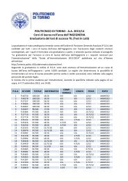
Figure 35. SPI Master-slave Interconnection<br />
MSB MASTER LSB<br />
MISO MISO MSB SLAVE LSB<br />
8-BIT SHIFT REGISTER<br />
8-BIT SHIFT REGISTER<br />
MOSI<br />
MOSI<br />
SPI<br />
CLOCK GENERATOR<br />
SCK<br />
SS<br />
V CC<br />
SCK<br />
SS<br />
The system is single-buffered in the transmit direction and double-buffered in the<br />
receive direction. This means that bytes to be transmitted cannot be written to the SPI<br />
Data Register before the entire shift cycle is completed. When receiving data, however,<br />
a received byte must be read from the SPI Data Register before the next byte has been<br />
completely shifted in. Otherwise, the first byte is lost.<br />
When the SPI is enabled, the data direction of the MOSI, MISO, SCK and SS pins is<br />
overridden according to Table 15.<br />
Table 15. SPI Pin Overrides<br />
Pin Direction, Master SPI Direction, Slave SPI<br />
MOSI User Defined Input<br />
MISO Input User Defined<br />
SCK User Defined Input<br />
SS User Defined Input<br />
Note: See “Alternate Functions of Port B” on page 66 for a detailed description of how to define<br />
the direction of the user-defined SPI pins.<br />
SS Pin Functionality<br />
48 AT90S8515<br />
When the SPI is configured as a master (MSTR in SPCR is set), the user can determine<br />
the direction of the SS pin. If SS is configured as an output, the pin is a general output<br />
pin, which does not affect the SPI system. If SS is configured as an input, it must be held<br />
high to ensure master SPI operation. If the SS pin is driven low by peripheral circuitry<br />
when the SPI is configured as master with the SS pin defined as an input, the SPI system<br />
interprets this as another master selecting the SPI as a slave and starts to send<br />
data to it. To avoid bus contention, the SPI system takes the following actions:<br />
1. The MSTR bit in SPCR is cleared and the SPI system becomes a slave. As a<br />
result of the SPI becoming a slave, the MOSI and SCK pins become inputs.<br />
2. The SPIF flag in SPSR is set, and if the SPI interrupt is enabled and the I-bit in<br />
SREG is set, the interrupt routine will be executed.<br />
Thus, when interrupt-driven SPI transmittal is used in Master Mode and there exists a<br />
possibility that SS is driven low, the interrupt should always check that the MSTR bit is<br />
still set. Once the MSTR bit has been cleared by a slave select, it must be set by the<br />
user to re-enable SPI Master Mode.<br />
When the SPI is configured as a slave, the SS pin is always input. When SS is held low,<br />
the SPI is activated and MISO becomes an output if configured so by the user. All other<br />
0841G–09/01