
Create successful ePaper yourself
Turn your PDF publications into a flip-book with our unique Google optimized e-Paper software.
Features<br />
• Utilizes the AVR ® RISC Architecture<br />
• AVR – High-performance and Low-power RISC Architecture<br />
– 118 Powerful Instructions – Most Single Clock Cycle Execution<br />
– 32 x 8 General-purpose Working Registers<br />
– Up to 8 MIPS Throughput at 8 MHz<br />
• Data and Nonvolatile Program Memory<br />
– 8K Bytes of In-System Programmable Flash<br />
Endurance: 1,000 Write/Erase Cycles<br />
– 512 Bytes of SRAM<br />
– 512 Bytes of In-System Programmable EEPROM<br />
Endurance: 100,000 Write/Erase Cycles<br />
– Programming Lock for Flash Program and EEPROM Data Security<br />
• Peripheral Features<br />
– One 8-bit Timer/Counter with Separate Prescaler<br />
– One 16-bit Timer/Counter with Separate Prescaler<br />
Compare, Capture Modes and Dual 8-, 9-, or 10-bit PWM<br />
– On-chip Analog Comparator<br />
– Programmable Watchdog Timer with On-chip Oscillator<br />
– Programmable Serial UART<br />
– Master/Slave SPI Serial Interface<br />
• Special Microcontroller Features<br />
– Low-power Idle and Power-down Modes<br />
– External and Internal Interrupt Sources<br />
• Specifications<br />
– Low-power, High-speed CMOS Process Technology<br />
– Fully Static Operation<br />
• Power Consumption at 4 MHz, 3V, 25°C<br />
– Active: 3.0 mA<br />
– Idle Mode: 1.0 mA<br />
– Power-down Mode:
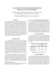
Pin Configurations<br />
2 AT90S8515<br />
0841G–09/01
AT90S8515<br />
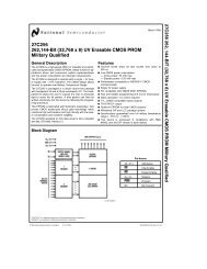
Description<br />
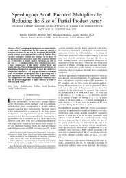
Block Diagram<br />
The AT90S8515 is a low-power CMOS 8-bit microcontroller based on the AVR RISC<br />
architecture. By executing powerful instructions in a single clock cycle, the AT90S8515<br />
achieves throughputs approaching 1 MIPS per MHz, allowing the system designer to<br />
optimize power consumption versus processing speed.<br />
Figure 1. The AT90S8515 Block Diagram<br />
The AVR core combines a rich instruction set with 32 general-purpose working registers.<br />
All the 32 registers are directly connected to the Arithmetic Logic Unit (ALU),<br />
allowing two independent registers to be accessed in one single instruction executed in<br />
0841G–09/01<br />
3
one clock cycle. The resulting architecture is more code efficient while achieving<br />
throughputs up to ten times faster than conventional CISC microcontrollers.<br />
The AT90S8515 provides the following features: 8K bytes of In-System Programmable<br />
Flash, 512 bytes EEPROM, 512 bytes SRAM, 32 general-purpose I/O lines, 32 generalpurpose<br />
working registers, flexible timer/counters with compare modes, internal and<br />
external interrupts, a programmable serial UART, programmable Watchdog Timer with<br />
internal oscillator, an SPI serial port and two software-selectable power-saving modes.<br />
The Idle Mode stops the CPU while allowing the SRAM, timer/counters, SPI port and<br />
interrupt system to continue functioning. The Power-down mode saves the register contents<br />
but freezes the oscillator, disabling all other chip functions until the next external<br />
interrupt or hardware reset.<br />
The device is manufactured using <strong>Atmel</strong>’s high-density nonvolatile memory technology.<br />
The On-chip In-System Programmable Flash allows the program memory to be reprogrammed<br />
In-System through an SPI serial interface or by a conventional nonvolatile<br />
memory programmer. By combining an enhanced RISC 8-bit CPU with In-System Programmable<br />
Flash on a monolithic chip, the <strong>Atmel</strong> AT90S8515 is a powerful<br />
microcontroller that provides a highly flexible and cost-effective solution to many embedded<br />
control applications.<br />
The AT90S8515 AVR is supported with a full suite of program and system development<br />
tools including: C compilers, macro assemblers, program debugger/simulators, in-circuit<br />
emulators and evaluation kits.<br />
Pin Descriptions<br />
VCC<br />
GND<br />
Port A (PA7..PA0)<br />
Port B (PB7..PB0)<br />
Port C (PC7..PC0)<br />
Port D (PD7..PD0)<br />
Supply voltage.<br />
Ground.<br />
Port A is an 8-bit bi-directional I/O port. Port pins can provide internal pull-up resistors<br />
(selected for each bit). The Port A output buffers can sink 20 mA and can drive LED displays<br />
directly. When pins PA0 to PA7 are used as inputs and are externally pulled low,<br />
they will source current if the internal pull-up resistors are activated. The Port A pins are<br />
tri-stated when a reset condition becomes active, even if the clock is not active.<br />
Port A serves as multiplexed address/data input/output when using external SRAM.<br />
Port B is an 8-bit bi-directional I/O port with internal pull-up resistors. The Port B output<br />
buffers can sink 20 mA. As inputs, Port B pins that are externally pulled low will source<br />
current if the pull-up resistors are activated. The Port B pins are tri-stated when a reset<br />
condition becomes active, even if the clock is not active.<br />
Port B also serves the functions of various special features of the AT90S8515 as listed<br />
on page 66.<br />
Port C is an 8-bit bi-directional I/O port with internal pull-up resistors. The Port C output<br />
buffers can sink 20 mA. As inputs, Port C pins that are externally pulled low will source<br />
current if the pull-up resistors are activated. The Port C pins are tri-stated when a reset<br />
condition becomes active, even if the clock is not active.<br />
Port C also serves as address output when using external SRAM.<br />
Port D is an 8-bit bi-directional I/O port with internal pull-up resistors. The Port D output<br />
buffers can sink 20 mA. As inputs, Port D pins that are externally pulled low will source<br />
4 AT90S8515<br />
0841G–09/01
AT90S8515<br />
current if the pull-up resistors are activated. The Port D pins are tri-stated when a reset<br />
condition becomes active, even if the clock is not active.<br />
Port D also serves the functions of various special features of the AT90S8515 as listed<br />
on page 73.<br />
RESET<br />
XTAL1<br />
XTAL2<br />
ICP<br />
OC1B<br />
ALE<br />
Reset input. A low level on this pin for more than 50 ns will generate a reset, even if the<br />
clock is not running. Shorter pulses are not guaranteed to generate a reset.<br />
Input to the inverting oscillator amplifier and input to the internal clock operating circuit.<br />
Output from the inverting oscillator amplifier.<br />
ICP is the input pin for the Timer/Counter1 Input Capture function.<br />
OC1B is the output pin for the Timer/Counter1 Output CompareB function.<br />
ALE is the Address Latch Enable used when the External Memory is enabled. The ALE<br />
strobe is used to latch the low-order address (8 bits) into an address latch during the first<br />
access cycle, and the AD0 - 7 pins are used for data during the second access cycle.<br />
0841G–09/01<br />
5
Crystal Oscillator<br />
XTAL1 and XTAL2 are input and output, respectively, of an inverting amplifier that can<br />
be configured for use as an on-chip oscillator, as shown in Figure 2. Either a quartz<br />
crystal or a ceramic resonator may be used. To drive the device from an external clock<br />
source, XTAL2 should be left unconnected while XTAL1 is driven as shown in Figure 3.<br />
Figure 2. Oscillator Connections<br />
MAX 1 HC BUFFER<br />
HC<br />
C2<br />
C1<br />
XTAL2<br />
XTAL1<br />
GND<br />
Note:<br />
When using the MCU oscillator as a clock for an external device, an HC buffer should be<br />
connected as indicated in the figure.<br />
Figure 3. External Clock Drive Configuration<br />
6 AT90S8515<br />
0841G–09/01
AT90S8515<br />
Architectural<br />
Overview<br />
The fast-access register file concept contains 32 x 8-bit general-purpose working registers<br />
with a single clock cycle access time. This means that during one single clock cycle,<br />
one ALU (Arithmetic Logic Unit) operation is executed. Two operands are output from<br />
the register file, the operation is executed and the result is stored back in the register file<br />
– in one clock cycle.<br />
Six of the 32 registers can be used as three 16-bit indirect address register pointers for<br />
Data Space addressing, enabling efficient address calculations. One of the three<br />
address pointers is also used as the address pointer for the constant table look-up function.<br />
These added function registers are the 16-bit X-, Y-, and Z-register.<br />
The ALU supports arithmetic and logic functions between registers or between a constant<br />
and a register. Single register operations are also executed in the ALU. Figure 4<br />
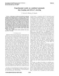
shows the AT90S8515 AVR RISC microcontroller architecture.<br />
In addition to the register operation, the conventional memory addressing modes can be<br />
used on the register file as well. This is enabled by the fact that the register file is<br />
assigned the 32 lowermost Data Space addresses ($00 - $1F), allowing them to be<br />
accessed as though they were ordinary memory locations.<br />
The I/O memory space contains 64 addresses for CPU peripheral functions such as<br />
Control Registers, Timer/Counters, A/D converters and other I/O functions. The I/O<br />
memory can be accessed directly or as the Data Space locations following those of the<br />
register file, $20 - $5F.<br />
The AVR uses a Harvard architecture concept – with separate memories and buses for<br />
program and data. The program memory is executed with a two-stage pipeline. While<br />
one instruction is being executed, the next instruction is pre-fetched from the program<br />
memory. This concept enables instructions to be executed in every clock cycle. The program<br />
memory is In-System Programmable Flash memory.<br />
With the relative jump and call instructions, the whole 4K address space is directly<br />
accessed. Most AVR instructions have a single 16-bit word format. Every program<br />
memory address contains a 16- or 32-bit instruction.<br />
During interrupts and subroutine calls, the return address Program Counter (PC) is<br />
stored on the stack. The stack is effectively allocated in the general data SRAM and<br />
consequently, the stack size is only limited by the total SRAM size and the usage of the<br />
SRAM. All user programs must initialize the SP in the reset routine (before subroutines<br />
or interrupts are executed). The 16-bit Stack Pointer (SP) is read/write-accessible in the<br />
I/O space.<br />
The 512-byte data SRAM can be easily accessed through the five different addressing<br />
modes supported in the AVR architecture.<br />
The memory spaces in the AVR architecture are all linear and regular memory maps.<br />
0841G–09/01<br />
7
Figure 4. The AT90S8515 AVR RISC Architecture<br />
Data Bus 8-bit<br />
4K x 16<br />
Program<br />
Memory<br />
Program<br />
Counter<br />
Status<br />
and Test<br />
Control<br />
Registers<br />
Instruction<br />
Register<br />
Instruction<br />
Decoder<br />
Control Lines<br />
Direct Addressing<br />
Indirect Addressing<br />
32 x 8<br />
General<br />
Purpose<br />
Registers<br />
ALU<br />
512 x 8<br />
Data<br />
SRAM<br />
Interrupt<br />
Unit<br />
SPI<br />
Unit<br />
Serial<br />
UART<br />
8-bit<br />
Timer/Counter<br />
16-bit<br />
Timer/Counter<br />
with PWM<br />
Watchdog<br />
Timer<br />
512 x 8<br />
EEPROM<br />
Analog<br />
Comparator<br />
32<br />
I/O Lines<br />
A flexible interrupt module has its control registers in the I/O space with an additional<br />
global interrupt enable bit in the status register. All the different interrupts have a separate<br />
interrupt vector in the interrupt vector table at the beginning of the program<br />
memory. The different interrupts have priority in accordance with their interrupt vector<br />
position. The lower the interrupt vector address, the higher the priority.<br />
8 AT90S8515<br />
0841G–09/01
AT90S8515<br />
Figure 5. Memory Maps<br />
Program Memory<br />
$000<br />
Data Memory<br />
32 Gen. Purpose $0000<br />
Working Registers $001F<br />
$0020<br />
Program FLASH<br />
(4K x 16)<br />
64 I/O Registers<br />
$005F<br />
$0060<br />
Internal SRAM<br />
(512 x 8)<br />
$025F<br />
$0260<br />
$FFF<br />
External SRAM<br />
(0 - 64K x 8)<br />
$FFFF<br />
0841G–09/01<br />
9
General-purpose<br />
Register File<br />
Figure 6 shows the structure of the 32 general-purpose working registers in the CPU.<br />
Figure 6. AVR CPU General-purpose Working Registers<br />
7 0 Addr.<br />
R0 $00<br />
R1 $01<br />
R2 $02<br />
…<br />
R13 $0D<br />
General R14 $0E<br />
Purpose R15 $0F<br />
Working R16 $10<br />
Registers R17 $11<br />
…<br />
R26 $1A X-register low byte<br />
R27 $1B X-register high byte<br />
R28 $1C Y-register low byte<br />
R29 $1D Y-register high byte<br />
R30 $1E Z-register low byte<br />
R31 $1F Z-register high byte<br />
All the register operating instructions in the instruction set have direct and single-cycle<br />
access to all registers. The only exception are the five constant arithmetic and logic<br />
instructions SBCI, SUBI, CPI, ANDI and ORI between a constant and a register and the<br />
LDI instruction for load immediate constant data. These instructions apply to the second<br />
half of the registers in the register file (R16..R31). The general SBC, SUB, CP, AND and<br />
OR and all other operations between two registers or on a single register apply to the<br />
entire register file.<br />
As shown in Figure 6, each register is also assigned a data memory address, mapping<br />
them directly into the first 32 locations of the user Data Space. Although not being physically<br />
implemented as SRAM locations, this memory organization provides great<br />
flexibility in access of the registers, as the X-, Y- and Z-registers can be set to index any<br />
register in the file.<br />
X-register, Y-register and<br />
Z-register<br />
The registers R26..R31 have some added functions to their general-purpose usage.<br />
These registers are address pointers for indirect addressing of the Data Space. The<br />
three indirect address registers X, Y, and Z are defined as:<br />
Figure 7. X-, Y-, and Z-registers<br />
15 0<br />
X - register 7 0 7 0<br />
R27 ($1B)<br />
R26 ($1A)<br />
15 0<br />
Y - register 7 0 7 0<br />
R29 ($1D)<br />
R28 ($1C)<br />
15 0<br />
Z - register 7 0 7 0<br />
R31 ($1F)<br />
R30 ($1E)<br />
10 AT90S8515<br />
0841G–09/01
AT90S8515<br />
In the different addressing modes these address registers have functions as fixed displacement,<br />
automatic increment and decrement (see the descriptions for the different<br />
instructions).<br />
ALU – Arithmetic Logic<br />
Unit<br />
In-System Programmable<br />
Flash Program Memory<br />
The high-performance AVR ALU operates in direct connection with all the 32 generalpurpose<br />
working registers. Within a single clock cycle, ALU operations between registers<br />
in the register file are executed. The ALU operations are divided into three main<br />
categories: arithmetic, logical and bit functions.<br />
The AT90S8515 contains 8K bytes On-chip In-System Programmable Flash memory for<br />
program storage. Since all instructions are 16- or 32-bit words, the Flash is organized as<br />
4K x 16. The Flash memory has an endurance of at least 1000 write/erase cycles. The<br />
AT90S8515 Program Counter (PC) is 12 bits wide, thus addressing the 4096 program<br />
memory addresses.<br />
See page 86 for a detailed description of Flash data downloading.<br />
See page 13 for the different program memory addressing modes.<br />
0841G–09/01<br />
11
SRAM Data Memory –<br />
Internal and External<br />
Figure 8 shows how the AT90S8515 SRAM memory is organized.<br />
Figure 8. SRAM Organization<br />
Register File<br />
Data Address Space<br />
R0 $0000<br />
R1 $0001<br />
R2 $0002<br />
…<br />
…<br />
R29 $001D<br />
R30 $001E<br />
R31 $001F<br />
I/O Registers<br />
$00 $0020<br />
$01 $0021<br />
$02 $0022<br />
…<br />
…<br />
$3D $005D<br />
$3E $005E<br />
$3F $005F<br />
Internal SRAM<br />
$0060<br />
$0061<br />
…<br />
$025E<br />
$025F<br />
External SRAM<br />
$0260<br />
$0261<br />
…<br />
$FFFE<br />
$FFFF<br />
The lower 608 data memory locations address the Register file, the I/O memory and the<br />
internal data SRAM. The first 96 locations address the Register file + I/O memory, and<br />
the next 512 locations address the internal data SRAM. An optional external data SRAM<br />
can be placed in the same SRAM memory space. This SRAM will occupy the location<br />
following the internal SRAM and up to as much as 64K - 1, depending on SRAM size.<br />
When the addresses accessing the data memory space exceed the internal data SRAM<br />
locations, the external data SRAM is accessed using the same instructions as for the<br />
internal data SRAM access. When the internal data space is accessed, the read and<br />
write strobe pins (RD and WR) are inactive during the whole access cycle. External<br />
SRAM operation is enabled by setting the SRE bit in the MCUCR register. See page 29<br />
for details.<br />
Accessing external SRAM takes one additional clock cycle per byte compared to access<br />
of the internal SRAM. This means that the commands LD, ST, LDS, STS, PUSH and<br />
POP take one additional clock cycle. If the stack is placed in external SRAM, interrupts,<br />
subroutine calls and returns take two clock cycles extra because the 2-byte program<br />
counter is pushed and popped. When external SRAM interface is used with wait state,<br />
12 AT90S8515<br />
0841G–09/01
AT90S8515<br />
two additional clock cycles is used per byte. This has the following effect: Data transfer<br />
instructions take two extra clock cycles, whereas interrupt, subroutine calls and returns<br />
will need four clock cycles more than specified in the instruction set manual.<br />
The five different addressing modes for the data memory cover: Direct, Indirect with Displacement,<br />
Indirect, Indirect with Pre-decrement and Indirect with Post-increment. In the<br />
register file, registers R26 to R31 feature the indirect addressing pointer registers.<br />
The direct addressing reaches the entire data space.<br />
The Indirect with Displacement mode features 63 address locations reached from the<br />
base address given by the Y- or Z-register.<br />
When using register indirect addressing modes with automatic pre-decrement and postincrement,<br />
the address registers X, Y and Z are decremented and incremented.<br />
The 32 general-purpose working registers, 64 I/O registers, the 512 bytes of internal<br />
data SRAM, and the 64K bytes of optional external data SRAM in the AT90S8515 are all<br />
accessible through all these addressing modes.<br />
See the next section for a detailed description of the different addressing modes.<br />
Program and Data<br />
Addressing Modes<br />
Register Direct, Single<br />
Register RD<br />
The AT90S8515 AVR RISC microcontroller supports powerful and efficient addressing<br />
modes for access to the program memory (Flash) and data memory (SRAM, Register<br />
file and I/O memory). This section describes the different addressing modes supported<br />
by the AVR architecture. In the figures, OP means the operation code part of the instruction<br />
word. To simplify, not all figures show the exact location of the addressing bits.<br />
Figure 9. Direct Single Register Addressing<br />
The operand is contained in register d (Rd).<br />
0841G–09/01<br />
13
Register Direct, Two Registers<br />
Rd and Rr<br />
Figure 10. Direct Register Addressing, Two Registers<br />
Operands are contained in register r (Rr) and d (Rd). The result is stored in register d<br />
(Rd).<br />
I/O Direct<br />
Figure 11. I/O Direct Addressing<br />
Operand address is contained in six bits of the instruction word. n is the destination or<br />
source register address.<br />
Data Direct<br />
Figure 12. Direct Data Addressing<br />
14 AT90S8515<br />
0841G–09/01
AT90S8515<br />
A 16-bit data address is contained in the 16 LSBs of a 2-word instruction. Rd/Rr specify<br />
the destination or source register.<br />
Data Indirect with<br />
Displacement<br />
Figure 13. Data Indirect with Displacement<br />
Operand address is the result of the Y- or Z-register contents added to the address contained<br />
in six bits of the instruction word.<br />
Data Indirect<br />
Figure 14. Data Indirect Addressing<br />
Operand address is the contents of the X-, Y-, or the Z-register.<br />
Data Indirect with Predecrement<br />
Figure 15. Data Indirect Addressing with Pre-decrement<br />
0841G–09/01<br />
15
The X-, Y-, or the Z-register is decremented before the operation. Operand address is<br />
the decremented contents of the X-, Y-, or the Z-register.<br />
Data Indirect with Postincrement<br />
Figure 16. Data Indirect Addressing with Post-increment<br />
The X-, Y-, or the Z-register is incremented after the operation. Operand address is the<br />
content of the X-, Y-, or the Z-register prior to incrementing.<br />
Constant Addressing Using<br />
the LPM Instruction<br />
Figure 17. Code Memory Constant Addressing<br />
15 1 0<br />
PROGRAM MEMORY<br />
$000<br />
Z-REGISTER<br />
$FFF<br />
Constant byte address is specified by the Z-register contents. The 15 MSBs select word<br />
address (0 - 4K), the LSB selects low byte if cleared (LSB = 0) or high byte if set (LSB =<br />
1).<br />
16 AT90S8515<br />
0841G–09/01
AT90S8515<br />
Indirect Program Addressing,<br />
IJMP and ICALL<br />
Figure 18. Indirect Program Memory Addressing<br />
15 0<br />
PROGRAM MEMORY<br />
$000<br />
Z-REGISTER<br />
$FFF<br />
Program execution continues at address contained by the Z-register (i.e., the PC is<br />
loaded with the contents of the Z-register).<br />
Relative Program Addressing,<br />
RJMP and RCALL<br />
Figure 19. Relative Program Memory Addressing<br />
PROGRAM MEMORY<br />
$000<br />
15 0<br />
PC<br />
+1<br />
15 12 11<br />
0<br />
OP<br />
k<br />
$FFF<br />
Program execution continues at address PC + k + 1. The relative address k is -2048 to<br />
2047.<br />
EEPROM Data Memory<br />
Memory Access Times<br />
and Instruction<br />
Execution Timing<br />
The AT90S8515 contains 512 bytes of data EEPROM memory. It is organized as a separate<br />
data space, in which single bytes can be read and written. The EEPROM has an<br />
endurance of at least 100,000 write/erase cycles. The access between the EEPROM<br />
and the CPU is described on page 44, specifying the EEPROM address registers, the<br />
EEPROM data register and the EEPROM control register.<br />
For the SPI data downloading, see page 86 for a detailed description.<br />
This section describes the general access timing concepts for instruction execution and<br />
internal memory access.<br />
The AVR CPU is driven by the System Clock Ø, directly generated from the external<br />
clock crystal for the chip. No internal clock division is used.<br />
Figure 20 shows the parallel instruction fetches and instruction executions enabled by<br />
the Harvard architecture and the fast-access register file concept. This is the basic pipelining<br />
concept to obtain up to 1 MIPS per MHz with the corresponding unique results for<br />
functions per cost, functions per clocks and functions per power unit.<br />
0841G–09/01<br />
17
Figure 20. The Parallel Instruction Fetches and Instruction Executions<br />
T1 T2 T3 T4<br />
System Clock Ø<br />
1st Instruction Fetch<br />
1st Instruction Execute<br />
2nd Instruction Fetch<br />
2nd Instruction Execute<br />
3rd Instruction Fetch<br />
3rd Instruction Execute<br />
4th Instruction Fetch<br />
Figure 21 shows the internal timing concept for the register file. In a single clock cycle<br />
an ALU operation using two register operands is executed and the result is stored back<br />
to the destination register.<br />
Figure 21. Single Cycle ALU Operation<br />
T1 T2 T3 T4<br />
System Clock Ø<br />
Total Execution Time<br />
Register Operands Fetch<br />
ALU Operation Execute<br />
Result Write Back<br />
The internal data SRAM access is performed in two System Clock cycles as described<br />
in Figure 22.<br />
Figure 22. On-chip Data SRAM Access Cycles<br />
T1 T2 T3 T4<br />
System Clock Ø<br />
Address<br />
Prev. Address<br />
Address<br />
Data<br />
WR<br />
Data<br />
RD<br />
Read Write<br />
See “Interface to External SRAM” on page 60 for a description of the access to the<br />
external SRAM.<br />
18 AT90S8515<br />
0841G–09/01
AT90S8515<br />
I/O Memory The I/O space definition of the AT90S8515 is shown in Table 1.<br />
Table 1. AT90S8515 I/O Space<br />
Address Hex Name Function<br />
$3F ($5F) SREG Status Register<br />
$3E ($5E) SPH Stack Pointer High<br />
$3D ($5D) SPL Stack Pointer Low<br />
$3B ($5B) GIMSK General Interrupt Mask register<br />
$3A ($5A) GIFR General Interrupt Flag Register<br />
$39 ($59) TIMSK Timer/Counter Interrupt Mask register<br />
$38 ($58) TIFR Timer/Counter Interrupt Flag register<br />
$35 ($55) MCUCR MCU general Control Register<br />
$33 ($53) TCCR0 Timer/Counter0 Control Register<br />
$32 ($52) TCNT0 Timer/Counter0 (8-bit)<br />
$2F ($4F) TCCR1A Timer/Counter1 Control Register A<br />
$2E ($4E) TCCR1B Timer/Counter1 Control Register B<br />
$2D ($4D) TCNT1H Timer/Counter1 High Byte<br />
$2C ($4C) TCNT1L Timer/Counter1 Low Byte<br />
$2B ($4B) OCR1AH Timer/Counter1 Output Compare Register A High Byte<br />
$2A ($4A) OCR1AL Timer/Counter1 Output Compare Register A Low Byte<br />
$29 ($49) OCR1BH Timer/Counter1 Output Compare Register B High Byte<br />
$28 ($48) OCR1BL Timer/Counter1 Output Compare Register B Low Byte<br />
$25 ($45) ICR1H T/C 1 Input Capture Register High Byte<br />
$24 ($44) ICR1L T/C 1 Input Capture Register Low Byte<br />
$21 ($41) WDTCR Watchdog Timer Control Register<br />
$1F ($3E) EEARH EEPROM Address Register High Byte (AT90S8515)<br />
$1E ($3E) EEARL EEPROM Address Register Low Byte<br />
$1D ($3D) EEDR EEPROM Data Register<br />
$1C ($3C) EECR EEPROM Control Register<br />
$1B ($3B) PORTA Data Register, Port A<br />
$1A ($3A) DDRA Data Direction Register, Port A<br />
$19 ($39) PINA Input Pins, Port A<br />
$18 ($38) PORTB Data Register, Port B<br />
$17 ($37) DDRB Data Direction Register, Port B<br />
$16 ($36) PINB Input Pins, Port B<br />
$15 ($35) PORTC Data Register, Port C<br />
$14 ($34) DDRC Data Direction Register, Port C<br />
$13 ($33) PINC Input Pins, Port C<br />
$12 ($32) PORTD Data Register, Port D<br />
0841G–09/01<br />
19
Table 1. AT90S8515 I/O Space (Continued)<br />
Address Hex Name Function<br />
Note:<br />
$11 ($31) DDRD Data Direction Register, Port D<br />
$10 ($30) PIND Input Pins, Port D<br />
$0F ($2F) SPDR SPI I/O Data Register<br />
$0E ($2E) SPSR SPI Status Register<br />
$0D ($2D) SPCR SPI Control Register<br />
$0C ($2C) UDR UART I/O Data Register<br />
$0B ($2B) USR UART Status Register<br />
$0A ($2A) UCR UART Control Register<br />
$09 ($29) UBRR UART Baud Rate Register<br />
$08 ($28) ACSR Analog Comparator Control and Status Register<br />
Reserved and unused locations are not shown in the table.<br />
All AT90S8515 I/Os and peripherals are placed in the I/O space. The I/O locations are<br />
accessed by the IN and OUT instructions transferring data between the 32 general-purpose<br />
working registers and the I/O space. I/O registers within the address range $00 -<br />
$1F are directly bit-accessible using the SBI and CBI instructions. In these registers, the<br />
value of single bits can be checked by using the SBIS and SBIC instructions. Refer to<br />
the instruction set section for more details. When using the I/O-specific commands IN<br />
and OUT, the I/O addresses $00 - $3F must be used. When addressing I/O registers as<br />
SRAM, $20 must be added to this address. All I/O register addresses throughout this<br />
document are shown with the SRAM address in parentheses.<br />
For compatibility with future devices, reserved bits should be written to zero if accessed.<br />
Reserved I/O memory addresses should never be written.<br />
Some of the status flags are cleared by writing a logical “1” to them. Note that the CBI<br />
and SBI instructions will operate on all bits in the I/O register, writing a “1” back into any<br />
flag read as set, thus clearing the flag. The CBI and SBI instructions work with registers<br />
$00 to $1F only.<br />
The I/O and peripherals control registers are explained in the following sections.<br />
Status Register – SREG<br />
The AVR status register (SREG) at I/O space location $3F ($5F) is defined as:<br />
Bit 7 6 5 4 3 2 1 0<br />
$3F ($5F) I T H S V N Z C SREG<br />
Read/Write R/W R/W R/W R/W R/W R/W R/W R/W<br />
Initial Value 0 0 0 0 0 0 0 0<br />
• Bit 7 – I: Global Interrupt Enable<br />
The global interrupt enable bit must be set (one) for the interrupts to be enabled. The<br />
individual interrupt enable control is then performed in separate control registers. If the<br />
global interrupt enable bit is cleared (zero), none of the interrupts are enabled independent<br />
of the individual interrupt enable settings. The I-bit is cleared by hardware after an<br />
interrupt has occurred and is set by the RETI instruction to enable subsequent<br />
interrupts.<br />
• Bit 6 – T: Bit Copy Storage<br />
The bit copy instructions BLD (Bit LoaD) and BST (Bit STore) use the T-bit as source<br />
and destination for the operated bit. A bit from a register in the register file can be copied<br />
20 AT90S8515<br />
0841G–09/01
AT90S8515<br />
into T by the BST instruction and a bit in T can be copied into a bit in a register in the<br />
register file by the BLD instruction.<br />
• Bit 5 – H: Half-carry Flag<br />
The half-carry flag H indicates a half-carry in some arithmetic operations. See the<br />
Instruction Set description for detailed information.<br />
• Bit 4 – S: Sign Bit, S = N⊄⊕ V<br />
The S-bit is always an exclusive or between the negative flag N and the two’s complement<br />
overflow flag V. See the Instruction Set description for detailed information.<br />
• Bit 3 – V: Two’s Complement Overflow Flag<br />
The two’s complement overflow flag V supports two’s complement arithmetics. See the<br />
Instruction Set description for detailed information.<br />
• Bit 2 – N: Negative Flag<br />
The negative flag N indicates a negative result after the different arithmetic and logic<br />
operations. See the Instruction Set description for detailed information.<br />
• Bit 1 – Z: Zero Flag<br />
The zero flag Z indicates a zero result after the different arithmetic and logic operations.<br />
See the Instruction Set description for detailed information.<br />
• Bit 0 – C: Carry Flag<br />
The carry flag C indicates a carry in an arithmetic or logic operation. See the Instruction<br />
Set description for detailed information.<br />
Note that the Status Register is not automatically stored when entering an interrupt routine<br />
and restored when returning from an interrupt routine. This must be handled by<br />
software.<br />
Stack Pointer – SP<br />
The general AVR 16-bit Stack Pointer is effectively built up of two 8-bit registers in the<br />
I/O space locations $3E ($5E) and $3D ($5D). As the AT90S8515 supports up to 64 Kb<br />
external SRAM, all 16 bits are used.<br />
Bit 15 14 13 12 11 10 9 8<br />
$3E ($5E) SP15 SP14 SP13 SP12 SP11 SP10 SP9 SP8 SPH<br />
$3D ($5D) SP7 SP6 SP5 SP4 SP3 SP2 SP1 SP0 SPL<br />
7 6 5 4 3 2 1 0<br />
Read/Write R/W R/W R/W R/W R/W R/W R/W R/W<br />
R/W R/W R/W R/W R/W R/W R/W R/W<br />
Initial Value 0 0 0 0 0 0 0 0<br />
0 0 0 0 0 0 0 0<br />
The Stack Pointer points to the data SRAM stack area where the Subroutine and Interrupt<br />
stacks are located. This stack space in the data SRAM must be defined by the<br />
program before any subroutine calls are executed or interrupts are enabled. The Stack<br />
Pointer must be set to point above $60. The Stack Pointer is decremented by 1 when<br />
data is pushed onto the stack with the PUSH instruction and it is decremented by 2<br />
when an address is pushed onto the stack with subroutine calls and interrupts. The<br />
Stack Pointer is incremented by 1 when data is popped from the stack with the POP<br />
instruction and it is incremented by 2 when an address is popped from the stack with<br />
return from subroutine RET or return from interrupt RETI.<br />
0841G–09/01<br />
21
Reset and Interrupt<br />
Handling<br />
The AT90S8515 provides 12 different interrupt sources. These interrupts and the separate<br />
reset vector each have a separate program vector in the program memory space.<br />
All interrupts are assigned individual enable bits that must be set (one) together with the<br />
I-bit in the Status Register in order to enable the interrupt.<br />
The lowest addresses in the program memory space are automatically defined as the<br />
Reset and Interrupt vectors. The complete list of vectors is shown in Table 2. The list<br />
also determines the priority levels of the different interrupts. The lower the address, the<br />
higher the priority level. RESET has the highest priority, and next is INT0 (the External<br />
Interrupt Request 0), etc.<br />
Table 2. Reset and Interrupt Vectors<br />
Vector No.<br />
Program<br />
Address Source Interrupt Definition<br />
1 $000 RESET<br />
External Reset, Power-on Reset and<br />
Watchdog Reset<br />
2 $001 INT0 External Interrupt Request 0<br />
3 $002 INT1 External Interrupt Request 1<br />
4 $003 TIMER1 CAPT Timer/Counter1 Capture Event<br />
5 $004 TIMER1 COMPA Timer/Counter1 Compare Match A<br />
6 $005 TIMER1 COMPB Timer/Counter1 Compare Match B<br />
7 $006 TIMER1 OVF Timer/Counter1 Overflow<br />
8 $007 TIMER0, OVF Timer/Counter0 Overflow<br />
9 $008 SPI, STC Serial Transfer Complete<br />
10 $009 UART, RX UART, Rx Complete<br />
11 $00A UART, UDRE UART Data Register Empty<br />
12 $00B UART, TX UART, Tx Complete<br />
13 $00C ANA_COMP Analog Comparator<br />
The most typical and general program setup for the Reset and Interrupt vector<br />
addresses are:<br />
Address Labels Code Comments<br />
$000 rjmp RESET ; Reset Handler<br />
$001 rjmp EXT_INT0 ; IRQ0 Handler<br />
$002 rjmp EXT_INT1 ; IRQ1 Handler<br />
$003 rjmp TIM1_CAPT ; Timer1 Capture Handler<br />
$004 rjmp TIM1_COMPA ; Timer1 CompareA Handler<br />
$005 rjmp TIM1_COMPB ; Timer1 CompareB Handler<br />
$006 rjmp TIM1_OVF ; Timer1 Overflow Handler<br />
$007 rjmp TIM0_OVF ; Timer0 Overflow Handler<br />
$008 rjmp SPI_STC ; SPI Transfer Complete Handler<br />
$009 rjmp UART_RXC ; UART RX Complete Handler<br />
$00a rjmp UART_DRE ; UDR Empty Handler<br />
$00b rjmp UART_TXC ; UART TX Complete Handler<br />
$00c rjmp ANA_COMP ; Analog Comparator Handler<br />
;<br />
$00d MAIN: ldi r16,high(RAMEND); Main program start<br />
$00e out SPH,r16<br />
22 AT90S8515<br />
0841G–09/01
AT90S8515<br />
$00f ldi r16,low(RAMEND)<br />
$010 out SPL,r16<br />
$011 xxx<br />
… … … …<br />
Reset Sources<br />
The AT90S8515 has three sources of reset:<br />
• Power-on Reset. The MCU is reset when the supply voltage is below the Power-on<br />
Reset threshold (V POT ).<br />
• External Reset. The MCU is reset when a low level is present on the RESET pin for<br />
more than 50 ns.<br />
• Watchdog Reset. The MCU is reset when the Watchdog timer period expires and<br />
the Watchdog is enabled.<br />
During reset, all I/O registers are set to their initial values and the program starts execution<br />
from address $000. The instruction placed in address $000 must be an RJMP<br />
(relative jump) instruction to the reset handling routine. If the program never enables an<br />
interrupt source, the interrupt vectors are not used and regular program code can be<br />
placed at these locations. The circuit diagram in Figure 23 shows the reset logic. Table 3<br />
defines the timing and electrical parameters of the reset circuitry.<br />
Figure 23. Reset Logic<br />
Table 3. Reset Characteristics<br />
Symbol Parameter Min Typ Max Units<br />
V POT<br />
(Not<br />
e:)<br />
Power-on Reset Threshold Voltage (rising) 0.8 1.2 1.6 V<br />
Power-on Reset Threshold Voltage (falling) 0.2 0.4 0.6 V<br />
V RST RESET Pin Threshold Voltage – – 0.9 V CC V<br />
t TOUT<br />
Reset Delay Time-out Period FSTRT<br />
Unprogrammed<br />
11.0 16.0 21.0 ms<br />
t TOUT<br />
Note:<br />
Reset Delay Time-out Period FSTRT<br />
Programmed<br />
0.25 0.28 0.31 ms<br />
The Power-on Reset will not work unless the supply voltage has been below V POT<br />
(falling).<br />
0841G–09/01<br />
23
The user can select the start-up time according to typical oscillator start-up. The number<br />
of WDT oscillator cycles used for each time-out is shown in Table 4. The frequency of<br />
the Watchdog Oscillator is voltage-dependent as shown in “Typical Characteristics” on<br />
page 95.<br />
Table 4. Number of Watchdog Oscillator Cycles<br />
FSTRT Time-out at V CC = 5V Number of WDT Cycles<br />
Programmed 0.28 ms 256<br />
Unprogrammed 16.0 ms 16K<br />
Power-on Reset<br />
A Power-on Reset (POR) circuit ensures that the device is reset from power-on. As<br />
shown in Figure 23, an internal timer clocked from the Watchdog Timer oscillator prevents<br />
the MCU from starting until after a certain period after V CC has reached the Poweron<br />
Threshold Voltage (V POT ), regardless of the V CC rise time (see Figure 24). The<br />
FSTRT Fuse bit in the Flash can be programmed to give a shorter start-up time if a<br />
ceramic resonator or any other fast-start oscillator is used to clock the MCU.<br />
If the built-in start-up delay is sufficient, RESET can be connected to V CC directly or via<br />
an external pull-up resistor. By holding the pin low for a period after V CC has been<br />
applied, the Power-on Reset period can be extended. Refer to Figure 25 for a timing<br />
example of this.<br />
Figure 24. MCU Start-up, RESET Tied to V CC .<br />
VCC<br />
V POT<br />
RESET<br />
V RST<br />
TIME-OUT<br />
t TOUT<br />
INTERNAL<br />
RESET<br />
Figure 25. MCU Start-up, RESET Controlled Externally<br />
VCC<br />
V POT<br />
RESET<br />
V RST<br />
TIME-OUT<br />
t TOUT<br />
INTERNAL<br />
RESET<br />
24 AT90S8515<br />
0841G–09/01
AT90S8515<br />
External Reset<br />
An external reset is generated by a low level on the RESET pin. Reset pulses longer<br />
than 50 ns will generate a reset, even if the clock is not running. Shorter pulses are not<br />
guaranteed to generate a reset. When the applied signal reaches the Reset Threshold<br />
Voltage (V RST ) on its positive edge, the delay timer starts the MCU after the Time-out<br />
period t TOUT has expired.<br />
Figure 26. External Reset during Operation<br />
Watchdog Reset<br />
When the Watchdog times out, it will generate a short reset pulse of 1 XTAL cycle duration.<br />
On the falling edge of this pulse, the delay timer starts counting the Time-out period<br />
t TOUT . Refer to page 42 for details on operation of the Watchdog.<br />
Figure 27. Watchdog Reset during Operation<br />
Interrupt Handling<br />
The AT90S8515 has two 8-bit interrupt mask control registers; GIMSK (General Interrupt<br />
Mask register) and TIMSK (Timer/Counter Interrupt Mask register).<br />
When an interrupt occurs, the Global Interrupt Enable I-bit is cleared (zero) and all interrupts<br />
are disabled. The user software can set (one) the I-bit to enable nested interrupts.<br />
The I-bit is set (one) when a Return from Interrupt instruction (RETI) is executed.<br />
For interrupts triggered by events that can remain static (e.g., the Output Compare<br />
Register1 matching the value of Timer/Counter1), the interrupt flag is set when the event<br />
occurs. If the interrupt flag is cleared and the interrupt condition persists, the flag will not<br />
be set until the event occurs the next time.<br />
When the Program Counter is vectored to the actual interrupt vector in order to execute<br />
the interrupt handling routine, hardware clears the corresponding flag that generated the<br />
0841G–09/01<br />
25
interrupt. Some of the interrupt flags can also be cleared by writing a logical “1” to the<br />
flag bit position(s) to be cleared.<br />
If an interrupt condition occurs when the corresponding interrupt enable bit is cleared<br />
(zero), the interrupt flag will be set and remembered until the interrupt is enabled or the<br />
flag is cleared by software.<br />
If one or more interrupt conditions occur when the global interrupt enable bit is cleared<br />
(zero), the corresponding interrupt flag(s) will be set and remembered until the global<br />
interrupt enable bit is set (one) and will be executed by order of priority.<br />
Note that external level interrupt does not have a flag and will only be remembered for<br />
as long as the interrupt condition is active.<br />
General Interrupt Mask<br />
Register – GIMSK<br />
Bit 7 6 5 4 3 2 1 0<br />
$3B ($5B) INT1 INT0 – – – – – – GIMSK<br />
Read/Write R/W R/W R R R R R R<br />
Initial Value 0 0 0 0 0 0 0 0<br />
• Bit 7 – INT1: External Interrupt Request 1 Enable<br />
When the INT1 bit is set (one) and the I-bit in the Status Register (SREG) is set (one),<br />
the external pin interrupt is enabled. The Interrupt Sense Control1 bits 1/0 (ISC11 and<br />
ISC10) in the MCU general Control Register (MCUCR) define whether the external<br />
interrupt is activated on rising or falling edge of the INT1 pin or is level-sensed. Activity<br />
on the pin will cause an interrupt request even if INT1 is configured as an output. The<br />
corresponding interrupt of External Interrupt Request 1 is executed from program memory<br />
address $002. See also “External Interrupts”.<br />
• Bit 6 – INT0: External Interrupt Request 0 Enable<br />
When the INT0 bit is set (one) and the I-bit in the Status Register (SREG) is set (one),<br />
the external pin interrupt is enabled. The Interrupt Sense Control0 bits 1/0 (ISC01 and<br />
ISC00) in the MCU general Control Register (MCUCR) define whether the external<br />
interrupt is activated on rising or falling edge of the INT0 pin or is level-sensed. Activity<br />
on the pin will cause an interrupt request even if INT0 is configured as an output. The<br />
corresponding interrupt of External Interrupt Request 0 is executed from program memory<br />
address $001. See also “External Interrupts”.<br />
• Bits 5..0 – Res: Reserved Bits<br />
These bits are reserved bits in the AT90S8515 and always read as zero.<br />
General Interrupt Flag<br />
Register – GIFR<br />
Bit 7 6 5 4 3 2 1 0<br />
$3A ($5A) INTF1 INTF0 – – – – – – GIFR<br />
Read/Write R/W R/W R R R R R R<br />
Initial Value 0 0 0 0 0 0 0 0<br />
• Bit 7 – INTF1: External Interrupt Flag1<br />
When an edge on the INT1 pin triggers an interrupt request, the corresponding interrupt<br />
flag, INTF1 becomes set (one). If the I-bit in SREG and the corresponding interrupt<br />
enable bit, INT1 in GIMSK is set (one), the MCU will jump to the interrupt vector. The<br />
flag is cleared when the interrupt routine is executed. Alternatively, the flag can be<br />
cleared by writing a logical “1” to it. This flag is always cleared when INT1 is configured<br />
as level interrupt.<br />
26 AT90S8515<br />
0841G–09/01
AT90S8515<br />
• Bit 6 – INTF0: External Interrupt Flag0<br />
When an edge on the INT0 pin triggers an interrupt request, the corresponding interrupt<br />
flag, INTF0, becomes set (one). If the I-bit in SREG and the corresponding interrupt<br />
enable bit, INT0 in GIMSK are set (one), the MCU will jump to the interrupt vector. The<br />
flag is cleared when the interrupt routine is executed. Alternatively, the flag is cleared by<br />
writing a logical “1” to it. This flag is always cleared when INT0 is configured as level<br />
interrupt.<br />
• Bits 5..0 – Res: Reserved Bits<br />
These bits are reserved bits in the AT90S8515 and always read as zero.<br />
Timer/Counter Interrupt Mask<br />
Register – TIMSK<br />
Bit 7 6 5 4 3 2 1 0<br />
$39 ($59) TOIE1 OCIE1A OCIE1B – TICIE1 – TOIE0 – TIMSK<br />
Read/Write R/W R/W R/W R R/W R R/W R<br />
Initial Value 0 0 0 0 0 0 0 0<br />
• Bit 7 – TOIE1: Timer/Counter1 Overflow Interrupt Enable<br />
When the TOIE1 bit is set (one) and the I-bit in the Status Register is set (one), the<br />
Timer/Counter1 Overflow interrupt is enabled. The corresponding interrupt (at vector<br />
$006) is executed if an overflow in Timer/Counter1 occurs, i.e., when the TOV1 bit is set<br />
in the Timer/Counter Interrupt Flag Register (TIFR).<br />
• Bit 6 – OCE1A: Timer/Counter1 Output CompareA Match Interrupt Enable<br />
When the OCIE1A bit is set (one) and the I-bit in the Status Register is set (one), the<br />
Timer/Counter1 CompareA Match interrupt is enabled. The corresponding interrupt (at<br />
vector $004) is executed if a CompareA match in Timer/Counter1 occurs, i.e., when the<br />
OCF1A bit is set in the Timer/Counter Interrupt Flag Register (TIFR).<br />
• Bit 5 – OCIE1B: Timer/Counter1 Output CompareB Match Interrupt Enable<br />
When the OCIE1B bit is set (one) and the I-bit in the Status Register is set (one), the<br />
Timer/Counter1 CompareB Match interrupt is enabled. The corresponding interrupt (at<br />
vector $005) is executed if a CompareB match in Timer/Counter1 occurs, i.e., when the<br />
OCF1B bit is set in the Timer/Counter Interrupt Flag Register (TIFR).<br />
• Bit 4 – Res: Reserved Bit<br />
This bit is a reserved bit in the AT90S8515 and always reads zero.<br />
• Bit 3 – TICIE1: Timer/Counter1 Input Capture Interrupt Enable<br />
When the TICIE1 bit is set (one) and the I-bit in the Status Register is set (one), the<br />
Timer/Counter1 Input Capture Event interrupt is enabled. The corresponding interrupt<br />
(at vector $003) is executed if a capture-triggering event occurs on pin 31, ICP, i.e.,<br />
when the ICF1 bit is set in the Timer/Counter Interrupt Flag Register (TIFR).<br />
• Bit 2 – Res: Reserved Bit<br />
This bit is a reserved bit in the AT90S8515 and always reads zero.<br />
• Bit 1 – TOIE0: Timer/Counter0 Overflow Interrupt Enable<br />
When the TOIE0 bit is set (one) and the I-bit in the Status Register is set (one), the<br />
Timer/Counter0 Overflow interrupt is enabled. The corresponding interrupt (at vector<br />
$007) is executed if an overflow in Timer/Counter0 occurs, i.e., when the TOV0 bit is set<br />
in the Timer/Counter Interrupt Flag Register (TIFR).<br />
• Bit 0 – Res: Reserved Bit<br />
This bit is a reserved bit in the AT90S8515 and always reads zero.<br />
0841G–09/01<br />
27
Timer/Counter Interrupt Flag<br />
Register – TIFR<br />
Bit 7 6 5 4 3 2 1 0<br />
$38 ($58) TOV1 OCF1A OCIFB – ICF1 – TOV0 – TIFR<br />
Read/Write R/W R/W R/W R R/W R R/W R<br />
Initial Value 0 0 0 0 0 0 0 0<br />
• Bit 7 – TOV1: Timer/Counter1 Overflow Flag<br />
The TOV1 is set (one) when an overflow occurs in Timer/Counter1. TOV1 is cleared by<br />
hardware when executing the corresponding interrupt handling vector. Alternatively,<br />
TOV1 is cleared by writing a logical “1” to the flag. When the I-bit in SREG, TOIE1<br />
(Timer/Counter1 Overflow Interrupt Enable) and TOV1 are set (one), the<br />
Timer/Counter1 Overflow interrupt is executed. In PWM mode, this bit is set when<br />
Timer/Counter1 changes counting direction at $0000.<br />
• Bit 6 – OCF1A: Output Compare Flag 1A<br />
The OCF1A bit is set (one) when compare match occurs between the Timer/Counter1<br />
and the data in OCR1A (Output Compare Register 1A). OCF1A is cleared by hardware<br />
when executing the corresponding interrupt handling vector. Alternatively, OCF1A is<br />
cleared by writing a logical “1” to the flag. When the I-bit in SREG, OCIE1A<br />
(Timer/Counter1 Compare Match InterruptA Enable) and the OCF1A are set (one), the<br />
Timer/Counter1 CompareA Match interrupt is executed.<br />
• Bit 5 – OCF1B: Output Compare Flag 1B<br />
The OCF1B bit is set (one) when compare match occurs between the Timer/Counter1<br />
and the data in OCR1B (Output Compare Register 1B). OCF1B is cleared by hardware<br />
when executing the corresponding interrupt handling vector. Alternatively, OCF1B is<br />
cleared by writing a logical “1” to the flag. When the I-bit in SREG, OCIE1B<br />
(Timer/Counter1 Compare Match InterruptB Enable) and the OCF1B are set (one), the<br />
Timer/Counter1 CompareB Match interrupt is executed.<br />
• Bit 4 – Res: Reserved Bit<br />
This bit is a reserved bit in the AT90S8515 and always reads zero.<br />
• Bit 3 – ICF1: Input Capture Flag 1<br />
The ICF1 bit is set (one) to flag an input capture event, indicating that the<br />
Timer/Counter1 value has been transferred to the input capture register (ICR1). ICF1 is<br />
cleared by hardware when executing the corresponding interrupt handling vector. Alternatively,<br />
ICF1 is cleared by writing a logical “1” to the flag. When the SREG I-bit, TICIE1<br />
(Timer/Counter1 Input Capture Interrupt Enable) and ICF1 are set (one), the<br />
Timer/Counter1 Capture interrupt is executed.<br />
• Bit 2 – Res: Reserved Bit<br />
This bit is a reserved bit in the AT90S8515 and always reads zero.<br />
• Bit 1 – TOV: Timer/Counter0 Overflow Flag<br />
The bit TOV0 is set (one) when an overflow occurs in Timer/Counter0. TOV0 is cleared<br />
by hardware when executing the corresponding interrupt handling vector. Alternatively,<br />
TOV0 is cleared by writing a logical “1” to the flag. When the SREG I-bit, TOIE0<br />
(Timer/Counter0 Overflow Interrupt Enable) and TOV0 are set (one), the<br />
Timer/Counter0 Overflow interrupt is executed.<br />
• Bit 0 – Res: Reserved Bit<br />
This bit is a reserved bit in the AT90S8515 and always reads zero.<br />
28 AT90S8515<br />
0841G–09/01
AT90S8515<br />
External Interrupts<br />
Interrupt Response Time<br />
MCU Control Register –<br />
MCUCR<br />
The external interrupts are triggered by the INT1 and INT0 pins. Observe that, if<br />
enabled, the interrupts will trigger even if the INT0/INT1 pins are configured as outputs.<br />
This feature provides a way of generating a software interrupt. The external interrupts<br />
can be triggered by a falling or rising edge or a low level. This is set up as indicated in<br />
the specification for the MCU Control Register (MCUCR). When the external interrupt is<br />
enabled and is configured as level-triggered, the interrupt will trigger as long as the pin<br />
is held low.<br />
The external interrupts are set up as described in the specification for the MCU Control<br />
Register (MCUCR).<br />
The interrupt execution response for all the enabled AVR interrupts is four clock cycles<br />
minimum. Four clock cycles after the interrupt flag has been set, the program vector<br />
address for the actual interrupt handling routine is executed. During this 4-clock-cycle<br />
period, the Program Counter (2 bytes) is pushed onto the stack and the Stack Pointer is<br />
decremented by 2. The vector is normally a relative jump to the interrupt routine, and<br />
this jump takes two clock cycles. If an interrupt occurs during execution of a multi-cycle<br />
instruction, this instruction is completed before the interrupt is served.<br />
A return from an interrupt handling routine (same as for a subroutine call routine) takes<br />
four clock cycles. During these four clock cycles, the Program Counter (2 bytes) is<br />
popped back from the stack, the Stack Pointer is incremented by 2 and the I-flag in<br />
SREG is set. When the AVR exits from an interrupt, it will always return to the main program<br />
and execute one more instruction before any pending interrupt is served.<br />
Note that the Status Register (SREG) is not handled by the AVR hardware, for neither<br />
interrupts nor subroutines. For the interrupt handling routines requiring a storage of the<br />
SREG, this must be performed by user software.<br />
For interrupts triggered by events that can remain static (e.g., the Output Compare<br />
Register1 A matching the value of Timer/Counter1), the interrupt flag is set when the<br />
event occurs. If the interrupt flag is cleared and the interrupt condition persists, the flag<br />
will not be set until the event occurs the next time. Note that an external level interrupt<br />
will only be remembered for as long as the interrupt condition is active.<br />
The MCU Control Register contains control bits for general MCU functions.<br />
Bit 7 6 5 4 3 2 1 0<br />
$35 ($55) SRE SRW SE SM ISC11 ISC10 ISC01 ISC00 MCUCR<br />
Read/Write R/W R/W R/W R/W R/W R/W R/W R/W<br />
Initial Value 0 0 0 0 0 0 0 0<br />
• Bit 7 – SRE: External SRAM Enable<br />
When the SRE bit is set (one), the external data SRAM is enabled and the pin functions<br />
AD0 - 7 (Port A), A8 - 15 (Port C), WR and RD (Port D) are activated as the alternate pin<br />
functions. Then the SRE bit overrides any pin direction settings in the respective data<br />
direction registers. See “SRAM Data Memory – Internal and External” on page 12 for a<br />
description of the external SRAM pin functions. When the SRE bit is cleared (zero), the<br />
external data SRAM is disabled and the normal pin and data direction settings are used.<br />
• Bit 6 – SRW: External SRAM Wait State<br />
When the SRW bit is set (one), a one-cycle wait state is inserted in the external data<br />
SRAM access cycle. When the SRW bit is cleared (zero), the external data SRAM<br />
access is executed with the normal three-cycle scheme. See Figure 43 and Figure 44.<br />
0841G–09/01<br />
29
• Bit 5 – SE: Sleep Enable<br />
The SE bit must be set (one) to make the MCU enter the Sleep Mode when the SLEEP<br />
instruction is executed. To avoid the MCU entering the Sleep Mode, unless it is the programmer’s<br />
purpose, it is recommended to set the Sleep Enable (SE) bit just before the<br />
execution of the SLEEP instruction.<br />
• Bit 4 – SM: Sleep Mode<br />
This bit selects between the two available sleep modes. When SM is cleared (zero), Idle<br />
Mode is selected as Sleep Mode. When SM is set (one), Power-down mode is selected<br />
as Sleep Mode. For details, refer to the section “Sleep Modes”.<br />
• Bits 3, 2 – ISC11, ISC10: Interrupt Sense Control 1, Bit 1 and Bit 0<br />
The External Interrupt 1 is activated by the external pin INT1 if the SREG I-flag and the<br />
corresponding interrupt mask in the GIMSK are set. The level and edges on the external<br />
INT1 pin that activate the interrupt are defined in Table 5.<br />
Table 5. Interrupt 1 Sense Control<br />
ISC11 ISC10 Description<br />
0 0 The low level of INT1 generates an interrupt request.<br />
0 1 Reserved<br />
1 0 The falling edge of INT1 generates an interrupt request.<br />
1 1 The rising edge of INT1 generates an interrupt request.<br />
• Bits 1, 0 – ISC01, ISC00: Interrupt Sense Control 0, Bit 1 and Bit 0<br />
The External Interrupt 0 is activated by the external pin INT0 if the SREG I-flag and the<br />
corresponding interrupt mask are set. The level and edges on the external INT0 pin that<br />
activate the interrupt are defined in Table 6.<br />
Table 6. Interrupt 0 Sense Control<br />
ISC01 ISC00 Description<br />
0 0 The low level of INT0 generates an interrupt request.<br />
0 1 Reserved<br />
1 0 The falling edge of INT0 generates an interrupt request.<br />
1 1 The rising edge of INT0 generates an interrupt request.<br />
The value on the INTn pin is sampled before detecting edges. If edge interrupt is<br />
selected, pulses with a duration longer than one CPU clock period will generate an interrupt.<br />
Shorter pulses are not guaranteed to generate an interrupt. If low-level interrupt is<br />
selected, the low level must be held until the completion of the currently executing<br />
instruction to generate an interrupt. If enabled, a level-triggered interrupt will generate<br />
an interrupt request as long as the pin is held low.<br />
30 AT90S8515<br />
0841G–09/01
AT90S8515<br />
Sleep Modes<br />
Idle Mode<br />
Power-down Mode<br />
To enter the sleep modes, the SE bit in MCUCR must be set (one) and a SLEEP instruction<br />
must be executed. If an enabled interrupt occurs while the MCU is in a sleep mode,<br />
the MCU awakes, executes the interrupt routine and resumes execution from the<br />
instruction following SLEEP. The contents of the register file, SRAM and I/O memory<br />
are unaltered. If a reset occurs during Sleep Mode, the MCU wakes up and executes<br />
from the Reset vector.<br />
When the SM bit is cleared (zero), the SLEEP instruction forces the MCU into the Idle<br />
Mode, stopping the CPU but allowing Timer/Counters, Watchdog and the interrupt system<br />
to continue operating. This enables the MCU to wake up from external triggered<br />
interrupts as well as internal ones like Timer Overflow interrupt and Watchdog reset. If<br />
wake-up from the Analog Comparator interrupt is not required, the Analog Comparator<br />
can be powered down by setting the ACD-bit in the Analog Comparator Control and Status<br />
Register (ACSR). This will reduce power consumption in Idle Mode. When the MCU<br />
wakes up from Idle Mode, the CPU starts program execution immediately.<br />
When the SM bit is set (one), the SLEEP instruction forces the MCU into the Powerdown<br />
mode. In this mode, the external oscillator is stopped, while the external interrupts<br />
and the Watchdog (if enabled) continue operating. Only an external reset, a Watchdog<br />
reset (if enabled), or an external level interrupt on INT0 or INT1 can wake up the MCU.<br />
Note that when a level-triggered interrupt is used for wake-up from power-down, the low<br />
level must be held for a time longer than the reset delay Time-out period t TOUT . Otherwise,<br />
the MCU will fail to wake up.<br />
0841G–09/01<br />
31
Timer/Counters<br />
Timer/Counter Prescaler<br />
The AT90S8515 provides two general-purpose Timer/Counters – one 8-bit T/C and one<br />
16-bit T/C. The Timer/Counters have individual prescaling selection from the same 10-<br />
bit prescaling timer. Both Timer/Counters can either be used as a timer with an internal<br />
clock time base or as a counter with an external pin connection that triggers the<br />
counting.<br />
Figure 28 shows the general Timer/Counter prescaler.<br />
Figure 28. Timer/Counter Prescaler<br />
TCK1<br />
TCK0<br />
The four different prescaled selections are: CK/8, CK/64, CK/256 and CK/1024, where<br />
CK is the oscillator clock. For the two Timer/Counters, added selections such as CK,<br />
external source and stop can be selected as clock sources.<br />
8-bit Timer/Counter0<br />
Figure 29 shows the block diagram for Timer/Counter0.<br />
The 8-bit Timer/Counter0 can select clock source from CK, prescaled CK or an external<br />
pin. In addition, it can be stopped as described in the specification for the<br />
Timer/Counter0 Control Register (TCCR0). The overflow status flag is found in the<br />
Timer/Counter Insterrupt Flag Register (TIFR). Control signals are found in the<br />
Timer/Counter0 Control Register (TCCR0). The interrupt enable/disable settings for<br />
Timer/Counter0 are found in the Timer/Counter Interrupt Mask Register (TIMSK).<br />
When Timer/Counter0 is externally clocked, the external signal is synchronized with the<br />
oscillator frequency of the CPU. To assure proper sampling of the external clock, the<br />
minimum time between two external clock transitions must be at least one internal CPU<br />
clock period. The external clock signal is sampled on the rising edge of the internal CPU<br />
clock.<br />
The 8-bit Timer/Counter0 features both a high-resolution and a high-accuracy usage<br />
with the lower prescaling opportunities. Similarly, the high prescaling opportunities make<br />
the Timer/Counter0 useful for lower speed functions or exact timing functions with infrequent<br />
actions.<br />
32 AT90S8515<br />
0841G–09/01
AT90S8515<br />
Figure 29. Timer/Counter0 Block Diagram<br />
Timer/Counter0 Control<br />
Register – TCCR0<br />
Bit 7 6 5 4 3 2 1 0<br />
$33 ($53) – – – – – CS02 CS01 CS00 TCCR0<br />
Read/Write R R R R R R/W R/W R/W<br />
Initial Value 0 0 0 0 0 0 0 0<br />
• Bits 7..3 – Res: Reserved Bits<br />
These bits are reserved bits in the AT90S8515 and always read as zero.<br />
• Bits 2, 1, 0 – CS02, CS01, CS00: Clock Select0, Bits 2, 1 and 0<br />
The Clock Select0 bits 2, 1 and 0 define the prescaling source of Timer/Counter0.<br />
Table 7. Clock 0 Prescale Select<br />
CS02 CS01 CS00 Description<br />
0 0 0 Stop, the Timer/Counter0 is stopped.<br />
0 0 1 CK<br />
0 1 0 CK/8<br />
0 1 1 CK/64<br />
1 0 0 CK/256<br />
1 0 1 CK/1024<br />
1 1 0 External Pin T0, falling edge<br />
1 1 1 External Pin T0, rising edge<br />
0841G–09/01<br />
33
The Stop condition provides a Timer Enable/Disable function. The CK down divided<br />
modes are scaled directly from the CK oscillator clock. If the external pin modes are<br />
used for Timer/Counter0, transitions on PB0/(T0) will clock the counter even if the pin is<br />
configured as an output. This feature can give the user software control of the counting.<br />
Timer Counter0 – TCNT0<br />
Bit 7 6 5 4 3 2 1 0<br />
$32 ($52) MSB LSB TCNT0<br />
Read/Write R/W R/W R/W R/W R/W R/W R/W R/W<br />
Initial Value 0 0 0 0 0 0 0 0<br />
The Timer/Counter0 is realized as an up-counter with read and write access. If the<br />
Timer/Counter0 is written and a clock source is present, the Timer/Counter0 continues<br />
counting in the clock cycle following the write operation.<br />
16-bit Timer/Counter1<br />
Figure 30 shows the block diagram for Timer/Counter1.<br />
Figure 30. Timer/Counter1 Block Diagram<br />
T1<br />
The 16-bit Timer/Counter1 can select clock source from CK, prescaled CK or an external<br />
pin. In addition, it can be stopped as described in the specification for the<br />
Timer/Counter1 Control Registers (TCCR1A and TCCR1B). The different status flags<br />
(overflow, compare match and capture event) are found in the Timer/Counter Interrupt<br />
Flag Register (TIFR). Control signals are found in the Timer/Counter1 Control Registers<br />
34 AT90S8515<br />
0841G–09/01
AT90S8515<br />
(TCCR1A and TCCR1B). The interrupt enable/disable settings for Timer/Counter1 are<br />
found in the Timer/Counter Interrupt Mask Register (TIMSK).<br />
When Timer/Counter1 is externally clocked, the external signal is synchronized with the<br />
oscillator frequency of the CPU. To assure proper sampling of the external clock, the<br />
minimum time between two external clock transitions must be at least one internal CPU<br />
clock period. The external clock signal is sampled on the rising edge of the internal CPU<br />
clock.<br />
The 16-bit Timer/Counter1 features both a high-resolution and a high-accuracy usage<br />
with the lower prescaling opportunities. Similarly, the high prescaling opportunities make<br />
the Timer/Counter1 useful for lower speed functions or exact timing functions with infrequent<br />
actions.<br />
The Timer/Counter1 supports two Output Compare functions using the Output Compare<br />
Register 1 A and B (OCR1A and OCR1B) as the data sources to be compared to the<br />
Timer/Counter1 contents. The Output Compare functions include optional clearing of<br />
the counter on compareA match and actions on the Output Compare pins on both compare<br />
matches.<br />
Timer/Counter1 can also be used as an 8-, 9- or 10-bit Pulse Width Modulator. In this<br />
mode, the counter and the OCR1A/OCR1B registers serve as a dual, glitch-free, standalone<br />
PWM with centered pulses. Refer to page 47 for a detailed description of this<br />
function.<br />
The Input Capture function of Timer/Counter1 provides a capture of the Timer/Counter1<br />
contents to the Input Capture Register (ICR1), triggered by an external event on the<br />
input capture pin (ICP). The actual capture event settings are defined by the<br />
Timer/Counter1 Control Register (TCCR1B). In addition, the Analog Comparator can be<br />
set to trigger the Input Capture. Refer to “Analog Comparator” on page 59 for details on<br />
this. The ICP pin logic is shown in Figure 31.<br />
Figure 31. ICP Pin Schematic Diagram<br />
If the Noise Canceler function is enabled, the actual trigger condition for the capture<br />
event is monitored over four samples and all four must be equal to activate the capture<br />
flag.<br />
0841G–09/01<br />
35
Timer/Counter1 Control<br />
Register A – TCCR1A<br />
Bit 7 6 5 4 3 2 1 0<br />
$2F ($4F) COM1A1 COM1A0 COM1B1 COM1B0 – – PWM11 PWM10 TCCR1A<br />
Read/Write R/W R/W R/W R/W R R R/W R/W<br />
Initial Value 0 0 0 0 0 0 0 0<br />
• Bits 7, 6 – COM1A1, COM1A0: Compare Output Mode1A, Bits 1 and 0<br />
The COM1A1 and COM1A0 control bits determine any output pin action following a<br />
compare match in Timer/Counter1. Any output pin actions affect pin OC1A (Output<br />
CompareA pin 1). This is an alternative function to an I/O port and the<br />
corresponding direction control bit must be set (one) to control the output pin. The control<br />
configuration is shown in Table 8.<br />
• Bits 5, 4 – COM1B1, COM1B0: Compare Output Mode1B, Bits 1 and 0<br />
The COM1B1 and COM1B0 control bits determine any output pin action following a<br />
compare match in Timer/Counter1. Any output pin actions affect pin OC1B (Output<br />
CompareB). The control configuration is given in Table 8.<br />
Table 8. Compare 1 Mode Select<br />
COM1X1 COM1X0 Description<br />
0 0 Timer/Counter1 disconnected from output pin OC1X<br />
0 1 Toggle the OC1X output line.<br />
1 0 Clear the OC1X output line (to zero).<br />
1 1 Set the OC1X output line (to one).<br />
Note: X = A or B<br />
In PWM mode, these bits have a different function. Refer to Table 12 on page 40 for a<br />
detailed description.<br />
• Bits 3..2 – Res: Reserved Bits<br />
These bits are reserved bits in the AT90S8515 and always read zero.<br />
• Bits 1..0 – PWM11, PWM10: Pulse Width Modulator Select Bits 1 and 0<br />
These bits select PWM operation of Timer/Counter1 as specified in Table 9. This mode<br />
is described on page 40.<br />
Table 9. PWM Mode Select<br />
PWM11 PWM10 Description<br />
0 0 PWM operation of Timer/Counter1 is disabled<br />
0 1 Timer/Counter1 is an 8-bit PWM<br />
1 0 Timer/Counter1 is a 9-bit PWM<br />
1 1 Timer/Counter1 is a 10-bit PWM<br />
36 AT90S8515<br />
0841G–09/01
AT90S8515<br />
Timer/Counter1 Control<br />
Register B – TCCR1B<br />
Bit 7 6 5 4 3 2 1 0<br />
$2E ($4E) ICNC1 ICES1 – – CTC1 CS12 CS11 CS10 TCCR1B<br />
Read/Write R/W R/W R R R/W R/W R/W R/W<br />
Initial Value 0 0 0 0 0 0 0 0<br />
• Bit 7 – ICNC1: Input Capture1 Noise Canceler (4 CKs)<br />
When the ICNC1 bit is cleared (zero), the input capture trigger noise canceler function is<br />
disabled. The input capture is triggered at the first rising/falling edge sampled on the ICP<br />
(input capture pin) as specified. When the ICNC1 bit is set (one), four successive samples<br />
are measured on the ICP, and all samples must be high/low according to the input<br />
capture trigger specification in the ICES1 bit. The actual sampling frequency is XTAL<br />
clock frequency.<br />
• Bit 6 – ICES1: Input Capture1 Edge Select<br />
While the ICES1 bit is cleared (zero), the Timer/Counter1 contents are transferred to the<br />
Input Capture Register (ICR1) on the falling edge of the input capture pin (ICP). While<br />
the ICES1 bit is set (one), the Timer/Counter1 contents are transferred to the ICR1 on<br />
the rising edge of the ICP.<br />
• Bits 5, 4 – Res: Reserved Bits<br />
These bits are reserved bits in the AT90S8515 and always read zero.<br />
• Bit 3 – CTC1: Clear Timer/Counter1 on Compare Match<br />
When the CTC1 control bit is set (one), the Timer/Counter1 is reset to $0000 in the clock<br />
cycle after a compareA match. If the CTC1 control bit is cleared, Timer/Counter1 continues<br />
counting and is unaffected by a compare match. Since the compare match is<br />
detected in the CPU clock cycle following the match, this function will behave differently<br />
when a prescaling higher than 1 is used for the timer. When a prescaling of 1 is used,<br />
and the compareA register is set to C, the timer will count as follows if CTC1 is set:<br />
... | C-2 | C-1 | C | 0 | 1 | ...<br />
When the prescaler is set to divide by 8, the timer will count like this:<br />
... | C-2, C-2, C-2, C-2, C-2, C-2, C-2, C-2 | C-1, C-1, C-1, C-1, C-1, C-1, C-1, C-1 | C, 0,<br />
0, 0, 0, 0, 0, 0 | ...<br />
In PWM mode, this bit has no effect.<br />
• Bits 2, 1, 0 – CS12, CS11, CS10: Clock Select1, Bits 2, 1 and 0<br />
The Clock Select1 bits 2, 1 and 0 define the prescaling source of Timer/Counter1.<br />
Table 10. Clock 1 Prescale Select<br />
CS12 CS11 CS10 Description<br />
0 0 0 Stop, the Timer/Counter1 is stopped.<br />
0 0 1 CK<br />
0 1 0 CK/8<br />
0 1 1 CK/64<br />
1 0 0 CK/256<br />
1 0 1 CK/1024<br />
1 1 0 External Pin T1, falling edge<br />
1 1 1 External Pin T1, rising edge<br />
0841G–09/01<br />
37
The Stop condition provides a Timer Enable/Disable function. The CK down divided<br />
modes are scaled directly from the CK oscillator clock. If the external pin modes are<br />
used for Timer/Counter1, transitions on PB1/(T1) will clock the counter even if the pin is<br />
configured as an output. This feature can give the user software control of the counting.<br />
Timer/Counter1 – TCNT1H<br />
AND TCNT1L<br />
Bit 15 14 13 12 11 10 9 8<br />
$2D ($4D) MSB TCNT1H<br />
$2C ($4C) LSB TCNT1L<br />
7 6 5 4 3 2 1 0<br />
Read/Write R/W R/W R/W R/W R/W R/W R/W R/W<br />
R/W R/W R/W R/W R/W R/W R/W R/W<br />
Initial Value 0 0 0 0 0 0 0 0<br />
0 0 0 0 0 0 0 0<br />
This 16-bit register contains the prescaled value of the 16-bit Timer/Counter1. To<br />
ensure that both the high and low bytes are read and written simultaneously when the<br />
CPU accesses these registers, the access is performed using an 8-bit<br />
temporary register (TEMP). This temporary register is also used when accessing<br />
OCR1A, OCR1B and ICR1. If the main program and interrupt routines perform access<br />
to registers using TEMP, interrupts must be disabled during access from the main program<br />
(and from interrupt routines if interrupts are allowed from within interrupt routines).<br />
• TCNT1 Timer/Counter1 Write:<br />
When the CPU writes to the high byte TCNT1H, the written data is placed in the<br />
TEMP register. Next, when the CPU writes the low byte TCNT1L, this byte of data is<br />
combined with the byte data in the TEMP register, and all 16 bits are written to the<br />
TCNT1 Timer/Counter1 register simultaneously. Consequently, the high byte<br />
TCNT1H must be accessed first for a full 16-bit register write operation.<br />
• TCNT1 Timer/Counter1 Read:<br />
When the CPU reads the low byte TCNT1L, the data of the low byte TCNT1L is sent<br />
to the CPU and the data of the high byte TCNT1H is placed in the TEMP register.<br />
When the CPU reads the data in the high byte TCNT1H, the CPU receives the data<br />
in the TEMP register. Consequently, the low byte TCNT1L must be accessed first for<br />
a full 16-bit register read operation.<br />
The Timer/Counter1 is realized as an up or up/down (in PWM mode) counter with read<br />
and write access. If Timer/Counter1 is written to and a clock source is selected, the<br />
Timer/Counter1 continues counting in the timer clock cycle after it is preset with the written<br />
value.<br />
Timer/Counter1 Output<br />
Compare Register – OCR1AH<br />
AND OCR1AL<br />
Bit 15 14 13 12 11 10 9 8<br />
$2B ($4B) MSB OCR1AH<br />
$2A ($4A) LSB OCR1AL<br />
7 6 5 4 3 2 1 0<br />
Read/Write R/W R/W R/W R/W R/W R/W R/W R/W<br />
R/W R/W R/W R/W R/W R/W R/W R/W<br />
Initial Value 0 0 0 0 0 0 0 0<br />
0 0 0 0 0 0 0 0<br />
38 AT90S8515<br />
0841G–09/01
AT90S8515<br />
Timer/Counter1 Output<br />
Compare Register – OCR1BH<br />
AND OCR1BL<br />
Bit 15 14 13 12 11 10 9 8<br />
$29 ($49) MSB OCR1BH<br />
$28 ($48) LSB OCR1BL<br />
7 6 5 4 3 2 1 0<br />
Read/Write R/W R/W R/W R/W R/W R/W R/W R/W<br />
R/W R/W R/W R/W R/W R/W R/W R/W<br />
Initial Value 0 0 0 0 0 0 0 0<br />
0 0 0 0 0 0 0 0<br />
The output compare registers are 16-bit read/write registers.<br />
The Timer/Counter1 Output Compare registers contain the data to be continuously compared<br />
with Timer/Counter1. Actions on compare matches are specified in the<br />
Timer/Counter1 Control and Status registers. A compare match only occurs if<br />
Timer/Counter1 counts to the OCR value. A software write that sets TCNT1 and OCR1A<br />
or OCR1B to the same value does not generate a compare match.<br />
A compare match will set the compare interrupt flag in the CPU clock cycle following the<br />
compare event.<br />
Since the Output Compare Registers (OCR1A and OCR1B) are 16-bit registers, a temporary<br />
register (TEMP) is used when OCR1A/B are written to ensure that both bytes are<br />
updated simultaneously. When the CPU writes the high byte, OCR1AH or OCR1BH, the<br />
data is temporarily stored in the TEMP register. When the CPU writes the low byte,<br />
OCR1AL or OCR1BL, the TEMP register is simultaneously written to OCR1AH or<br />
OCR1BH. Consequently, the high byte OCR1AH or OCR1BH must be written first for a<br />
full 16-bit register write operation.<br />
The TEMP register is also used when accessing TCNT1 and ICR1. If the main program<br />
and interrupt routines perform access to registers using TEMP, interrupts must be disabled<br />
during access from the main program (and from interrupt routines if interrupts are<br />
allowed from within interrupt routines).<br />
Timer/Counter1 Input Capture<br />
Register – ICR1H AND ICR1L<br />
Bit 15 14 13 12 11 10 9 8<br />
$25 ($45) MSB ICR1H<br />
$24 ($44) LSB ICR1L<br />
7 6 5 4 3 2 1 0<br />
Read/Write R R R R R R R R<br />
R R R R R R R R<br />
Initial Value 0 0 0 0 0 0 0 0<br />
0 0 0 0 0 0 0 0<br />
The input capture register is a 16-bit read-only register.<br />
When the rising or falling edge (according to the input capture edge setting [ICES1]) of<br />
the signal at the input capture pin (ICP) is detected, the current value of the<br />
Timer/Counter1 is transferred to the Input Capture Register (ICR1). At the same time,<br />
the input capture flag (ICF1) is set (one).<br />
Since the Input Capture Register (ICR1) is a 16-bit register, a temporary register<br />
(TEMP) is used when ICR1 is read to ensure that both bytes are read simultaneously.<br />
When the CPU reads the low byte ICR1L, the data is sent to the CPU and the data of<br />
the high byte ICR1H is placed in the TEMP register. When the CPU reads the data in<br />
the high byte ICR1H, the CPU receives the data in the TEMP register. Consequently,<br />
the low byte ICR1L must be accessed first for a full 16-bit register read operation.<br />
0841G–09/01<br />
39
The TEMP register is also used when accessing TCNT1, OCR1A and OCR1B. If the<br />
main program and interrupt routines perform access to registers using TEMP, interrupts<br />
must be disabled during access from the main program (and from interrupt routines if<br />
interrupts are allowed from within interrupt routines).<br />
Timer/Counter1 in PWM Mode<br />
When the PWM mode is selected, Timer/Counter1, the Output Compare Register1A<br />
(OCR1A) and the Output Compare Register1B (OCR1B) form a dual 8-, 9- or 10-bit,<br />
free-running, glitch-free and phase-correct PWM with outputs on the PD5(OC1A) and<br />
OC1B pins. Timer/Counter1 acts as an up/down counter, counting up from $0000 to<br />
TOP (see Table 11), where it turns and counts down again to zero before the cycle is<br />
repeated. When the counter value matches the contents of the 10 least significant bits of<br />
OCR1A or OCR1B, the PD5(OC1A)/OC1B pins are set or cleared according to the settings<br />
of the COM1A1/COM1A0 or COM1B1/COM1B0 bits in the Timer/Counter1 Control<br />
Register (TCCR1A). Refer to Table 12 for details.<br />
Table 11. Timer TOP Values and PWM Frequency<br />
PWM Resolution Timer TOP Value Frequency<br />
8-bit $00FF (255) f TCK1 /510<br />
9-bit $01FF (511) f TCK1 /1022<br />
10-bit $03FF(1023) f TCK1 /2046<br />
Table 12. Compare1 Mode Select in PWM Mode<br />
COM1X1 COM1X0 Effect on OCX1<br />
Note:<br />
0 0 Not connected<br />
0 1 Not connected<br />
1 0<br />
1 1<br />
X = A or B<br />
Cleared on compare match, up-counting. Set on compare match,<br />
down-counting (non-inverted PWM).<br />
Cleared on compare match, down-counting. Set on compare match,<br />
up-counting (inverted PWM).<br />
Note that in the PWM mode, the 10 least significant OCR1A/OCR1B bits, when written,<br />
are transferred to a temporary location. They are latched when Timer/Counter1 reaches<br />
the value TOP. This prevents the occurrence of odd-length PWM pulses (glitches) in the<br />
event of an unsynchronized OCR1A/OCR1B write. See Figure 32 for an example.<br />
40 AT90S8515<br />
0841G–09/01
AT90S8515<br />
Figure 32. Effects on Unsynchronized OCR1 Latching<br />
Compare Value changes<br />
Counter Value<br />
Compare Value<br />
PWM Output OC1X<br />
Synchronized<br />
OCR1X Latch<br />
Compare Value changes<br />
Counter Value<br />
Compare Value<br />
Unsynchronized OCR1X Latch Glitch<br />
PWM Output OC1X<br />
Note: X = A or B<br />
During the time between the write and the latch operation, a read from OCR1A or<br />
OCR1B will read the contents of the temporary location. This means that the most<br />
recently written value always will read out of OCR1A/B.<br />
When the OCR1 contains $0000 or TOP, the output OC1A/OC1B is updated to low or<br />
high on the next compare match according to the settings of COM1A1/COM1A0 or<br />
COM1B1/COM1B0. This is shown in Table 13.<br />
Note: If the compare register contains TOP value and the prescaler is not in use (CS12..CS10<br />
= 001), the PWM output will not produce any pulse at all, because up-counting and<br />
down-counting values are reached simultaneously. When the prescaler is in use<br />
(CS12..CS10 ≠ 001 or 000), the PWM output goes active when the counter reaches the<br />
TOP value; but the down-counting compare match is not interpreted to be reached<br />
before the next time the counter reaches the TOP value, making a one-period PWM<br />
pulse.<br />
Table 13. PWM Outputs OCR1X = $0000 or TOP<br />
Note:<br />
COM1X1 COM1X0 OCR1X Output OC1X<br />
1 0 $0000 L<br />
1 0 TOP H<br />
1 1 $0000 H<br />
1 1 TOP L<br />
X = A or B<br />
In PWM mode, the Timer Overflow Flag1 (TOV1) is set when the counter advances from<br />
$0000. Timer Overflow Interrupt1 operates exactly as in normal Timer/Counter mode,<br />
i.e., it is executed when TOV1 is set, provided that Timer Overflow Interrupt1 and global<br />
interrupts are enabled. This also applies to the Timer Output Compare1 flags and<br />
interrupts.<br />
0841G–09/01<br />
41
Watchdog Timer<br />
The Watchdog Timer is clocked from a separate On-chip oscillator that runs at 1 MHz.<br />
This is the typical value at V CC = 5V. See characterization data for typical values at other<br />
V CC levels. By controlling the Watchdog Timer prescaler, the Watchdog reset interval<br />
can be adjusted (see Table 14 for a detailed description). The WDR (Watchdog Reset)<br />
instruction resets the Watchdog Timer. Eight different clock cycle periods can be<br />
selected to determine the reset period. If the reset period expires without another<br />
Watchdog reset, the AT90S8515 resets and executes from the reset vector. For timing<br />
details on the Watchdog reset, refer to page 25.<br />
To prevent unintentional disabling of the Watchdog, a special turn-off sequence must be<br />
followed when the Watchdog is disabled. Refer to the description of the Watchdog Timer<br />
Control Register for details.<br />
Figure 33. Watchdog Timer<br />
Watchdog Timer Control<br />
Register – WDTCR<br />
Bit 7 6 5 4 3 2 1 0<br />
$21 ($41) – – – WDTOE WDE WDP2 WDP1 WDP0 WDTCR<br />
Read/Write R R R R/W R/W R/W R/W R/W<br />
Initial Value 0 0 0 0 0 0 0 0<br />
• Bits 7..5 – Res: Reserved Bits<br />
These bits are reserved bits in the AT90S8515 and will always read as zero.<br />
• Bit 4 – WDTOE: Watchdog Turn-off Enable<br />
This bit must be set (one) when the WDE bit is cleared. Otherwise, the Watchdog will<br />
not be disabled. Once set, hardware will clear this bit to zero after four clock cycles.<br />
Refer to the description of the WDE bit for a Watchdog disable procedure.<br />
• Bit 3 – WDE: Watchdog Enable<br />
When the WDE is set (one) the Watchdog Timer is enabled, and if the WDE is cleared<br />
(zero) the Watchdog Timer function is disabled. WDE can only be cleared if the WDTOE<br />
bit is set (one). To disable an enabled Watchdog Timer, the following procedure must be<br />
followed:<br />
42 AT90S8515<br />
0841G–09/01
AT90S8515<br />
1. In the same operation, write a logical “1” to WDTOE and WDE. A logical “1” must<br />
be written to WDE even though it is set to one before the disable operation starts.<br />
2. Within the next four clock cycles, write a logical “0” to WDE. This disables the<br />
Watchdog.<br />
• Bits 2..0 – WDP2, WDP1, WDP0: Watchdog Timer Prescaler 2, 1 and 0<br />
The WDP2, WDP1 and WDP0 bits determine the Watchdog Timer prescaling when the<br />
Watchdog Timer is enabled. The different prescaling values and their corresponding<br />
Time-out periods are shown in Table 14.<br />
Table 14. Watchdog Timer Prescale Select<br />
WDP2 WDP1 WDP0<br />
Number of WDT<br />
Oscillator Cycles<br />
Typical Time-out<br />
at V CC = 3.0V<br />
Typical Time-out<br />
at V CC = 5.0V<br />
0 0 0 16K cycles 47.0 ms 15.0 ms<br />
0 0 1 32K cycles 94.0 ms 30.0 ms<br />
0 1 0 64K cycles 0.19 s 60.0 ms<br />
0 1 1 128K cycles 0.38 s 0.12 s<br />
1 0 0 256K cycles 0.75 s 0.24 s<br />
1 0 1 512K cycles 1.5 s 0.49 s<br />
1 1 0 1,024K cycles 3.0 s 0.97 s<br />
1 1 1 2,048K cycles 6.0 s 1.9 s<br />
Note: The frequency of the Watchdog oscillator is voltage-dependent as shown in the Electrical<br />
Characteristics section.<br />
The WDR (Watchdog Reset) instruction should always be executed before the Watchdog<br />
Timer is enabled. This ensures that the reset period will be in accordance with the<br />
Watchdog Timer prescale settings. If the Watchdog Timer is enabled without reset, the<br />
Watchdog Timer may not start to count from zero.<br />
To avoid unintentional MCU reset, the Watchdog Timer should be disabled or reset<br />
before changing the Watchdog Timer Prescale Select.<br />
43<br />
0841G–09/01
EEPROM Read/Write<br />
Access<br />
EEPROM Address Register –<br />
EEARH and EEARL<br />
The EEPROM access registers are accessible in the I/O space.<br />
The write access time is in the range of 2.5 - 4 ms, depending on the V CC voltages. A<br />
self-timing function, however, lets the user software detect when the next byte can be<br />
written. If the user code contains code that writes the EEPROM, some precaution must<br />
be taken. In heavily filtered power supplies, V CC is likely to rise or fall slowly on powerup/down.<br />
This causes the device for some period of time to run at a voltage lower than<br />
specified as minimum for the clock frequency used. CPU operation under these conditions<br />
is likely cause the program counter to perform unintentional jumps and eventually<br />
execute the EEPROM write code. To secure EEPROM integrity, the user is advised to<br />
use an external under-voltage reset circuit in this case.<br />
In order to prevent unintentional EEPROM writes, a specific write procedure must be followed.<br />
Refer to the description of the EEPROM Control Register for details on this.<br />
When the EEPROM is written, the CPU is halted for two clock cycles before the next<br />
instruction is executed. When the EEPROM is read, the CPU is halted for four clock<br />
cycles before the next instruction is executed.<br />
Bit 15 14 13 12 11 10 9 8<br />
$1F ($3F) – – – – – – – EEAR8 EEARH<br />
$1E ($3E) EEAR7 EEAR6 EEAR5 EEAR4 EEAR3 EEAR2 EEAR1 EEAR0 EEARL<br />
7 6 5 4 3 2 1 0<br />
Read/Write R R R R R R R R/W<br />
R/W R/W R/W R/W R/W R/W R/W R/W<br />
Initial Value 0 0 0 0 0 0 0 0<br />
0 0 0 0 0 0 0 0<br />
The EEPROM address registers (EEARH and EEARL) specify the EEPROM address in<br />
the 512-byte EEPROM space for AT90S8515. The EEPROM data bytes are addressed<br />
linearly between 0 and 512.<br />
EEPROM Data Register –<br />
EEDR<br />
Bit 7 6 5 4 3 2 1 0<br />
$1D ($3D) MSB LSB EEDR<br />
Read/Write R/W R/W R/W R/W R/W R/W R/W R/W<br />
Initial Value 0 0 0 0 0 0 0 0<br />
• Bits 7..0 – EEDR7..0: EEPROM Data<br />
For the EEPROM write operation, the EEDR register contains the data to be written to<br />
the EEPROM in the address given by the EEAR register. For the EEPROM read operation,<br />
the EEDR contains the data read out from the EEPROM at the address given by<br />
EEAR.<br />
EEPROM Control Register –<br />
EECR<br />
Bit 7 6 5 4 3 2 1 0<br />
$1C ($3C) – – – – – EEMWE EEWE EERE EECR<br />
Read/Write R R R R R R/W R/W R/W<br />
Initial Value 0 0 0 0 0 0 0 0<br />
• Bits 7..3 – Res: Reserved Bits<br />
These bits are reserved bits in the AT90S8515 and will always read as zero.<br />
44 AT90S8515<br />
0841G–09/01
AT90S8515<br />
• Bit 2 – EEMWE: EEPROM Master Write Enable<br />
The EEMWE bit determines whether setting EEWE to one causes the EEPROM to be<br />
written. When EEMWE is set (one), setting EEWE will write data to the EEPROM at the<br />
selected address. If EEMWE is zero, setting EEWE will have no effect. When EEMWE<br />
has been set (one) by software, hardware clears the bit to zero after four clock cycles.<br />
See the description of the EEWE bit for a EEPROM write procedure.<br />
• Bit 1 – EEWE: EEPROM Write Enable<br />
The EEPROM Write Enable signal (EEWE) is the write strobe to the EEPROM. When<br />
address and data are correctly set up, the EEWE bit must be set to write the value into<br />
the EEPROM. The EEMWE bit must be set when the logical “1” is written to EEWE, otherwise<br />
no EEPROM write takes place. The following procedure should be followed<br />
when writing the EEPROM (the order of steps 2 and 3 is unessential):<br />
1. Wait until EEWE becomes zero.<br />
2. Write new EEPROM address to EEARL and EEARH (optional).<br />
3. Write new EEPROM data to EEDR (optional).<br />
4. Write a logical “1” to the EEMWE bit in EECR (to be able to write a logical “1” to<br />
the EEMWE bit, the EEWE bit must be written to zero in the same cycle).<br />
5. Within four clock cycles after setting EEMWE, write a logical “1” to EEWE.<br />
When the write access time (typically 2.5 ms at V CC = 5V or 4 ms at V CC = 2.7V) has<br />
elapsed, the EEWE bit is cleared (zero) by hardware. The user software can poll this bit<br />
and wait for a zero before writing the next byte. When EEWE has been set, the CPU is<br />
halted for two cycles before the next instruction is executed.<br />
Caution: An interrupt between step 4 and step 5 will make the write cycle fail, since the<br />
EEPROM Master Write Enable will time-out. If an interrupt routine accessing the<br />
EEPROM is interrupting another EEPROM access, the EEAR or EEDR registers will be<br />
modified, causing the interrupted EEPROM access to fail. It is recommended to have<br />
the global interrupt flag cleared during the four last steps to avoid these problems.<br />
• Bit 0 – EERE: EEPROM Read Enable<br />
The EEPROM Read Enable signal EERE is the read strobe to the EEPROM. When the<br />
correct address is set up in the EEAR register, the EERE bit must be set. When the<br />
EERE bit is cleared (zero) by hardware, requested data is found in the EEDR register.<br />
The EEPROM read access takes one instruction and there is no need to poll the EERE<br />
bit. When EERE has been set, the CPU is halted for four cycles before the next instruction<br />
is executed.<br />
The user should poll the EEWE bit before starting the read operation. If a write operation<br />
is in progress when new data or address is written to the EEPROM I/O registers, the<br />
write operation will be interrupted and the result is undefined.<br />
0841G–09/01<br />
45
Prevent EEPROM<br />
Corruption<br />
During periods of low V CC , the EEPROM data can be corrupted because the supply voltage<br />
is too low for the CPU and the EEPROM to operate properly. These issues are the<br />
same as for board level systems using the EEPROM and the same design solutions<br />
should be applied.<br />
An EEPROM data corruption can be caused by two situations when the voltage is too<br />
low. First, a regular write sequence to the EEPROM requires a minimum voltage to<br />
operate correctly. Second, the CPU itself can execute instructions incorrectly if the supply<br />
voltage for executing instructions is too low.<br />
EEPROM data corruption can easily be avoided by following these design recommendations<br />
(one is sufficient):<br />
1. Keep the AVR RESET active (low) during periods of insufficient power supply<br />
voltage. This is best done by an external low V CC Reset Protection circuit, often<br />
referred to as a Brown-out Detector (BOD). Please refer to application note AVR<br />
180 for design considerations regarding power-on reset and low-voltage<br />
detection.<br />
2. Keep the AVR core in Power-down Sleep mode during periods of low V CC . This<br />
will prevent the CPU from attempting to decode and execute instructions, effectively<br />
protecting the EEPROM registers from unintentional writes.<br />
3. Store constants in Flash memory if the ability to change memory contents from<br />
software is not required. Flash memory cannot be updated by the CPU and will<br />
not be subject to corruption.<br />
46 AT90S8515<br />
0841G–09/01
AT90S8515<br />
Serial Peripheral<br />
Interface – SPI<br />
The Serial Peripheral Interface (SPI) allows high-speed synchronous data transfer<br />
between the AT90S8515 and peripheral devices or between several AVR devices. The<br />
AT90S8515 SPI features include the following:<br />
• Full-duplex, 3-wire Synchronous Data Transfer<br />
• Master or Slave Operation<br />
• LSB First or MSB First Data Transfer<br />
• Four Programmable Bit Rates<br />
• End-of-Transmission Interrupt Flag<br />
• Write Collision Flag Protection<br />
• Wake-up from Idle Mode (Slave Mode Only)<br />
Figure 34. SPI Block Diagram<br />
The interconnection between master and slave CPUs with SPI is shown in Figure 35.<br />
The PB7(SCK) pin is the clock output in the Master Mode and is the clock input in the<br />
Slave Mode. Writing to the SPI Data Register of the master CPU starts the SPI clock<br />
generator and the data written shifts out of the PB5(MOSI) pin and into the PB5(MOSI)<br />
pin of the slave CPU. After shifting one byte, the SPI clock generator stops, setting the<br />
end-of-transmission flag (SPIF). If the SPI interrupt enable bit (SPIE) in the SPCR register<br />
is set, an interrupt is requested. The Slave Select input, PB4(SS), is set low to select<br />
an individual slave SPI device. The two shift registers in the master and the slave can be<br />
considered as one distributed 16-bit circular shift register. This is shown in Figure 35.<br />
When data is shifted from the master to the slave, data is also shifted in the opposite<br />
direction, simultaneously. This means that during one shift cycle, data in the master and<br />
the slave are interchanged.<br />
0841G–09/01<br />
47
Figure 35. SPI Master-slave Interconnection<br />
MSB MASTER LSB<br />
MISO MISO MSB SLAVE LSB<br />
8-BIT SHIFT REGISTER<br />
8-BIT SHIFT REGISTER<br />
MOSI<br />
MOSI<br />
SPI<br />
CLOCK GENERATOR<br />
SCK<br />
SS<br />
V CC<br />
SCK<br />
SS<br />
The system is single-buffered in the transmit direction and double-buffered in the<br />
receive direction. This means that bytes to be transmitted cannot be written to the SPI<br />
Data Register before the entire shift cycle is completed. When receiving data, however,<br />
a received byte must be read from the SPI Data Register before the next byte has been<br />
completely shifted in. Otherwise, the first byte is lost.<br />
When the SPI is enabled, the data direction of the MOSI, MISO, SCK and SS pins is<br />
overridden according to Table 15.<br />
Table 15. SPI Pin Overrides<br />
Pin Direction, Master SPI Direction, Slave SPI<br />
MOSI User Defined Input<br />
MISO Input User Defined<br />
SCK User Defined Input<br />
SS User Defined Input<br />
Note: See “Alternate Functions of Port B” on page 66 for a detailed description of how to define<br />
the direction of the user-defined SPI pins.<br />
SS Pin Functionality<br />
48 AT90S8515<br />
When the SPI is configured as a master (MSTR in SPCR is set), the user can determine<br />
the direction of the SS pin. If SS is configured as an output, the pin is a general output<br />
pin, which does not affect the SPI system. If SS is configured as an input, it must be held<br />
high to ensure master SPI operation. If the SS pin is driven low by peripheral circuitry<br />
when the SPI is configured as master with the SS pin defined as an input, the SPI system<br />
interprets this as another master selecting the SPI as a slave and starts to send<br />
data to it. To avoid bus contention, the SPI system takes the following actions:<br />
1. The MSTR bit in SPCR is cleared and the SPI system becomes a slave. As a<br />
result of the SPI becoming a slave, the MOSI and SCK pins become inputs.<br />
2. The SPIF flag in SPSR is set, and if the SPI interrupt is enabled and the I-bit in<br />
SREG is set, the interrupt routine will be executed.<br />
Thus, when interrupt-driven SPI transmittal is used in Master Mode and there exists a<br />
possibility that SS is driven low, the interrupt should always check that the MSTR bit is<br />
still set. Once the MSTR bit has been cleared by a slave select, it must be set by the<br />
user to re-enable SPI Master Mode.<br />
When the SPI is configured as a slave, the SS pin is always input. When SS is held low,<br />
the SPI is activated and MISO becomes an output if configured so by the user. All other<br />
0841G–09/01
AT90S8515<br />
pins are inputs. When SS is driven high, all pins are inputs and the SPI is passive, which<br />
means that it will not receive incoming data. Note that the SPI logic will be reset once<br />
the SS pin is brought high. If the SS pin is brought high during a transmission, the SPI<br />
will stop sending and receiving immediately and both data received and data sent must<br />
be considered as lost.<br />
Data Modes<br />
There are four combinations of SCK phase and polarity with respect to serial data,<br />
which are determined by control bits CPHA and CPOL. The SPI data transfer formats<br />
are shown in Figure 36 and Figure 37.<br />
Figure 36. SPI Transfer Format with CPHA = 0 and DORD = 0<br />
Figure 37. SPI Transfer Format with CPHA = 1 and DORD = 0<br />
SPI Control Register – SPCR<br />
Bit 7 6 5 4 3 2 1 0<br />
$0D ($2D) SPIE SPE DORD MSTR CPOL CPHA SPR1 SPR0 SPCR<br />
Read/Write R/W R/W R/W R/W R/W R/W R/W R/W<br />
Initial Value 0 0 0 0 0 0 0 0<br />
• Bit 7 – SPIE: SPI Interrupt Enable<br />
This bit causes the SPI interrupt to be executed if SPIF bit in the SPSR register is set<br />
and the global interrupts are enabled.<br />
• Bit 6 – SPE: SPI Enable<br />
When the SPE bit is set (one), the SPI is enabled. This bit must be set to enable any SPI<br />
operations.<br />
0841G–09/01<br />
49
• Bit 5 – DORD: Data Order<br />
When the DORD bit is set (one), the LSB of the data word is transmitted first.<br />
When the DORD bit is cleared (zero), the MSB of the data word is transmitted first.<br />
• Bit 4 – MSTR: Master/Slave Select<br />
This bit selects Master SPI Mode when set (one), and Slave SPI Mode when cleared<br />
(zero). If SS is configured as an input and is driven low while MSTR is set, MSTR will be<br />
cleared and SPIF in SPSR will become set. The user will then have to set MSTR to reenable<br />
SPI Master Mode.<br />
• Bit 3 – CPOL: Clock Polarity<br />
When this bit is set (one), SCK is high when idle. When CPOL is cleared (zero), SCK is<br />
low when idle. Refer to Figure 36 and Figure 37 for additional information.<br />
• Bit 2 – CPHA: Clock Phase<br />
Refer to Figure 36 or Figure 37 for the functionality of this bit.<br />
• Bits 1, 0 – SPR1, SPR0: SPI Clock Rate Select 1 and 0<br />
These two bits control the SCK rate of the device configured as a master. SPR1 and<br />
SPR0 have no effect on the slave. The relationship between SCK and the oscillator<br />
clock frequency f cl is shown in Table 16.<br />
Table 16. Relationship between SCK and the Oscillator Frequency<br />
SPR1 SPR0 SCK Frequency<br />
0 0 f cl /4<br />
0 1 f cl /16<br />
1 0 f cl /64<br />
1 1 f cl /128<br />
SPI Status Register – SPSR<br />
Bit 7 6 5 4 3 2 1 0<br />
$0E ($2E) SPIF WCOL – – – – – – SPSR<br />
Read/Write R R R R R R R R<br />
Initial Value 0 0 0 0 0 0 0 0<br />
• Bit 7 – SPIF: SPI Interrupt Flag<br />
When a serial transfer is complete, the SPIF bit is set (one) and an interrupt is generated<br />
if SPIE in SPCR is set (one) and global interrupts are enabled. If SS is an input and<br />
is driven low when the SPI is in Master Mode, this will also set the SPIF flag. SPIF is<br />
cleared by hardware when executing the corresponding interrupt handling vector. Alternatively,<br />
the SPIF bit is cleared by first reading the SPI Status Register when SPIF is set<br />
(one), then by accessing the SPI Data Register (SPDR).<br />
• Bit 6 – WCOL: Write Collision Flag<br />
The WCOL bit is set if the SPI Data Register (SPDR) is written during a data transfer.<br />
The WCOL bit (and the SPIF bit) are cleared (zero) by first reading the SPI Status Register<br />
when WCOL is set (one), and then by accessing the SPI Data Register.<br />
• Bits 5..0 – Res: Reserved Bits<br />
These bits are reserved bits in the AT90S8515 and will always read as zero.<br />
The SPI interface on the AT90S8515 is also used for program memory and EEPROM<br />
downloading or uploading. See page 86 for serial programming and verification.<br />
50 AT90S8515<br />
0841G–09/01
AT90S8515<br />
SPI Data Register – SPDR<br />
Bit 7 6 5 4 3 2 1 0<br />
$0F ($2F) MSB LSB SPDR<br />
Read/Write R/W R/W R/W R/W R/W R/W R/W R/W<br />
Initial Value x x x x x x x x Undefined<br />
The SPI Data Register is a read/write register used for data transfer between the register<br />
file and the SPI Shift Register. Writing to the register initiates data transmission.<br />
Reading the register causes the Shift Register Receive buffer to be read.<br />
0841G–09/01<br />
51
UART<br />
The AT90S8515 features a full duplex (separate receive and transmit registers) Universal<br />
Asynchronous Receiver and Transmitter (UART). The main features are:<br />
• Baud Rate Generator that can Generate a large Number of Baud Rates (bps)<br />
• High Baud Rates at Low XTAL Frequencies<br />
• 8 or 9 Bits Data<br />
• Noise Filtering<br />
• Overrun Detection<br />
• Framing Error Detection<br />
• False Start Bit Detection<br />
• Three separate Interrupts on TX Complete, TX Data Register Empty and RX Complete<br />
Data Transmission A block schematic of the UART transmitter is shown in Figure 38.<br />
Figure 38. UART Transmitter<br />
Data transmission is initiated by writing the data to be transmitted to the UART I/O Data<br />
Register, UDR. Data is transferred from UDR to the Transmit shift register when:<br />
• A new character has been written to UDR after the stop bit from the previous<br />
character has been shifted out. The shift register is loaded immediately.<br />
• A new character has been written to UDR before the stop bit from the previous<br />
character has been shifted out. The shift register is loaded when the stop bit of the<br />
character currently being transmitted has been shifted out.<br />
52 AT90S8515<br />
0841G–09/01
AT90S8515<br />
If the 10(11)-bit Transmitter shift register is empty, data is transferred from UDR to the<br />
shift register. At this time the UDRE (UART Data Register Empty) bit in the UART Status<br />
Register, USR, is set. When this bit is set (one), the UART is ready to receive the next<br />
character. At the same time as the data is transferred from UDR to the 10(11)-bit shift<br />
register, bit 0 of the shift register is cleared (start bit) and bit 9 or 10 is set (stop bit). If<br />
9-bit data word is selected (the CHR9 bit in the UART Control Register, UCR is set), the<br />
TXB8 bit in UCR is transferred to bit 9 in the Transmit shift register.<br />
On the baud rate clock following the transfer operation to the shift register, the start bit is<br />
shifted out on the TXD pin. Then follows the data, LSB first. When the stop bit has been<br />
shifted out, the shift register is loaded if any new data has been written to the UDR during<br />
the transmission. During loading, UDRE is set. If there is no new data in the UDR<br />
register to send when the stop bit is shifted out, the UDRE flag will remain set until UDR<br />
is written again. When no new data has been written and the stop bit has been present<br />
on TXD for one bit length, the TX Complete flag (TXC) in USR is set.<br />
The TXEN bit in UCR enables the UART Transmitter when set (one). When this bit is<br />
cleared (zero), the PD1 pin can be used for general I/O. When TXEN is set, the UART<br />
Transmitter will be connected to PD1, which is forced to be an output pin regardless of<br />
the setting of the DDD1 bit in DDRD.<br />
Data Reception<br />
Figure 39 shows a block diagram of the UART Receiver.<br />
Figure 39. UART Receiver<br />
0841G–09/01<br />
53
The receiver front-end logic samples the signal on the RXD pin at a frequency 16 times<br />
the baud rate. While the line is idle, one single sample of logical “0” will be interpreted as<br />
the falling edge of a start bit and the start bit detection sequence is initiated. Let sample<br />
1 denote the first zero-sample. Following the 1-to-0 transition, the receiver samples the<br />
RXD pin at samples 8, 9 and 10. If two or more of these three samples are found to be<br />
logical “1”s, the start bit is rejected as a noise spike and the receiver starts looking for<br />
the next 1-to-0 transition.<br />
If, however, a valid start bit is detected, sampling of the data bits following the start bit is<br />
performed. These bits are also sampled at samples 8, 9 and 10. The logical value found<br />
in at least two of the three samples is taken as the bit value. All bits are shifted into the<br />
Transmitter Shift register as they are sampled. Sampling of an incoming character is<br />
shown in Figure 40.<br />
Figure 40. Sampling Received Data<br />
When the stop bit enters the receiver, the majority of the three samples must be “1” to<br />
accept the stop bit. If two or more samples are logical “0”s, the Framing Error (FE) flag in<br />
the UART Status Register (USR) is set. Before reading the UDR register, the user<br />
should always check the FE bit to detect framing errors.<br />
Whether or not a valid stop bit is detected at the end of a character reception cycle, the<br />
data is transferred to UDR and the RXC flag in USR is set. UDR is in fact two physically<br />
separate registers, one for transmitted data and one for received data. When UDR is<br />
read, the Receive Data register is accessed, and when UDR is written, the Transmit<br />
Data register is accessed. If 9-bit data word is selected (the CHR9 bit in the UART Control<br />
Register, UCR is set), the RXB8 bit in UCR is loaded with bit 9 in the Transmit Shift<br />
register when data is transferred to UDR.<br />
If, after having received a character, the UDR register has not been read since the last<br />
receive, the OverRun (OR) flag in USR is set. This means that the last data byte shifted<br />
into the shift register could not be transferred to UDR and has been lost. The OR bit is<br />
buffered and is updated when the valid data byte in UDR is read. Thus, the user should<br />
always check the OR bit after reading the UDR register in order to detect any overruns if<br />
the baud rate is high or CPU load is high.<br />
When the RXEN bit in the UCR register is cleared (zero), the receiver is disabled. This<br />
means that the PD0 pin can be used as a general I/O pin. When RXEN is set, the UART<br />
Receiver will be connected to PD0, which is forced to be an input pin regardless of the<br />
setting of the DDD0 bit in DDRD. When PD0 is forced to input by the UART, the<br />
PORTD0 bit can still be used to control the pull-up resistor on the pin.<br />
When the CHR9 bit in the UCR register is set, transmitted and received characters are<br />
9 bits long, plus start and stop bits. The ninth data bit to be transmitted is the TXB8 bit in<br />
UCR register. This bit must be set to the wanted value before a transmission is initiated<br />
by writing to the UDR register. The ninth data bit received is the RXB8 bit in the UCR<br />
register.<br />
54 AT90S8515<br />
0841G–09/01
AT90S8515<br />
UART Control<br />
UART I/O Data Register – UDR<br />
Bit 7 6 5 4 3 2 1 0<br />
$0C ($2C) MSB LSB UDR<br />
Read/Write R/W R/W R/W R/W R/W R/W R/W R/W<br />
Initial Value 0 0 0 0 0 0 0 0<br />
The UDR register is actually two physically separate registers sharing the same I/O<br />
address. When writing to the register, the UART Transmit Data register is written. When<br />
reading from UDR, the UART Receive Data register is read.<br />
UART Status Register – USR<br />
Bit 7 6 5 4 3 2 1 0<br />
$0B ($2B) RXC TXC UDRE FE OR – – – USR<br />
Read/Write R R/W R R R R R R<br />
Initial Value 0 0 1 0 0 0 0 0<br />
The USR register is a read-only register providing information on the UART status.<br />
• Bit 7 – RXC: UART Receive Complete<br />
This bit is set (one) when a received character is transferred from the Receiver Shift register<br />
to UDR. The bit is set regardless of any detected framing errors. When the RXCIE<br />
bit in UCR is set, the UART Receive Complete interrupt will be executed when RXC is<br />
set (one). RXC is cleared by reading UDR. When interrupt-driven data reception is used,<br />
the UART Receive Complete Interrupt routine must read UDR in order to clear RXC,<br />
otherwise a new interrupt will occur once the interrupt routine terminates.<br />
• Bit 6 – TXC: UART Transmit Complete<br />
This bit is set (one) when the entire character (including the stop bit) in the Transmit<br />
Shift register has been shifted out and no new data has been written to UDR. This flag is<br />
especially useful in half-duplex communications interfaces, where a transmitting application<br />
must enter receive mode and free the communications bus immediately after<br />
completing the transmission.<br />
When the TXCIE bit in UCR is set, setting of TXC causes the UART Transmit Complete<br />
interrupt to be executed. TXC is cleared by hardware when executing the corresponding<br />
interrupt handling vector. Alternatively, the TXC bit is cleared (zero) by writing a logical<br />
“1” to the bit.<br />
• Bit 5 – UDRE: UART Data Register Empty<br />
This bit is set (one) when a character written to UDR is transferred to the Transmit Shift<br />
register. Setting of this bit indicates that the transmitter is ready to receive a new character<br />
for transmission.<br />
When the UDRIE bit in UCR is set, the UART Transmit Complete interrupt to be executed<br />
as long as UDRE is set. UDRE is cleared by writing UDR. When interrupt-driven<br />
data transmittal is used, the UART Data Register Empty Interrupt routine must write<br />
UDR in order to clear UDRE, otherwise a new interrupt will occur once the interrupt routine<br />
terminates.<br />
UDRE is set (one) during reset to indicate that the transmitter is ready.<br />
• Bit 4 – FE: Framing Error<br />
This bit is set if a Framing Error condition is detected, i.e., when the stop bit of an incoming<br />
character is zero.<br />
0841G–09/01<br />
55
The FE bit is cleared when the stop bit of received data is one.<br />
• Bit 3 – OR: Overrun<br />
This bit is set if an Overrun condition is detected, i.e., when a character already present<br />
in the UDR register is not read before the next character has been shifted into the<br />
Receiver Shift register. The OR bit is buffered, which means that it will be set once the<br />
valid data still in UDRE is read.<br />
The OR bit is cleared (zero) when data is received and transferred to UDR.<br />
• Bits 2..0 – Res: Reserved Bits<br />
These bits are reserved bits in the AT90S8515 and will always read as zero.<br />
UART Control Register – UCR<br />
Bit 7 6 5 4 3 2 1 0<br />
$0A ($2A) RXCIE TXCIE UDRIE RXEN TXEN CHR9 RXB8 TXB8 UCR<br />
Read/Write R/W R/W R/W R/W R/W R/W R W<br />
Initial Value 0 0 0 0 0 0 1 0<br />
• Bit 7 – RXCIE: RX Complete Interrupt Enable<br />
When this bit is set (one), a setting of the RXC bit in USR will cause the Receive Complete<br />
Interrupt routine to be executed provided that global interrupts are enabled.<br />
• Bit 6 – TXCIE: TX Complete Interrupt Enable<br />
When this bit is set (one), a setting of the TXC bit in USR will cause the Transmit Complete<br />
Interrupt routine to be executed provided that global interrupts are enabled.<br />
• Bit 5 – UDRIE: UART Data Register Empty Interrupt Enable<br />
When this bit is set (one), a setting of the UDRE bit in USR will cause the UART Data<br />
Register Empty Interrupt routine to be executed provided that global interrupts are<br />
enabled.<br />
• Bit 4 – RXEN: Receiver Enable<br />
This bit enables the UART receiver when set (one). When the receiver is disabled, the<br />
RXC, OR and FE status flags cannot become set. If these flags are set, turning off<br />
RXEN does not cause them to be cleared.<br />
• Bit 3 – TXEN: Transmitter Enable<br />
This bit enables the UART transmitter when set (one). When disabling the transmitter<br />
while transmitting a character, the transmitter is not disabled before the character in the<br />
shift register plus any following character in UDR has been completely transmitted.<br />
• Bit 2 – CHR9: 9-bit Characters<br />
When this bit is set (one) transmitted and received characters are 9 bits long plus start<br />
and stop bits. The ninth bit is read and written by using the RXB8 and TXB8 bits in UCR,<br />
respectively. The ninth data bit can be used as an extra stop bit or a parity bit.<br />
• Bit 1 – RXB8: Receive Data Bit 8<br />
When CHR9 is set (one), RXB8 is the ninth data bit of the received character.<br />
• Bit 0 – TXB8: Transmit Data Bit 8<br />
When CHR9 is set (one), TXB8 is the ninth data bit in the character to be transmitted.<br />
56 AT90S8515<br />
0841G–09/01
AT90S8515<br />
BAUD Rate Generator<br />
The baud rate generator is a frequency divider that generates baud rates according to<br />
the following equation:<br />
f CK<br />
BAUD = ------------------------------------<br />
16(UBRR + 1)<br />
• BAUD = Baud rate<br />
• f CK = Crystal Clock frequency<br />
• UBRR = Contents of the UART Baud Rate register, UBRR (0 - 255)<br />
For standard crystal frequencies, the most commonly used baud rates can be generated<br />
by using the UBRR settings in Table 17. UBRR values that yield an actual baud rate differing<br />
less than 2% from the target baud rate are boldface in the table. However, using<br />
baud rates that have more than 1% error is not recommended. High error ratings give<br />
less noise immunity.<br />
0841G–09/01<br />
57
Table 17. UBRR Settings at Various Crystal Frequencies<br />
Baud Rate 1MHz %Error 1.8432 MHz %Error 2MHz %Error 2.4576 MHz %Error<br />
2400 UBRR= 25 0.2 UBRR= 47 0.0 UBRR= 51 0.2 UBRR= 63 0.0<br />
4800 UBRR= 12 0.2 UBRR= 23 0.0 UBRR= 25 0.2 UBRR= 31 0.0<br />
9600 UBRR= 6 7.5 UBRR= 11 0.0 UBRR= 12 0.2 UBRR= 15 0.0<br />
14400 UBRR= 3 7.8 UBRR= 7 0.0 UBRR= 8 3.7 UBRR= 10 3.1<br />
19200 UBRR= 2 7.8 UBRR= 5 0.0 UBRR= 6 7.5 UBRR= 7 0.0<br />
28800 UBRR= 1 7.8 UBRR= 3 0.0 UBRR= 3 7.8 UBRR= 4 6.3<br />
38400 UBRR= 1 22.9 UBRR= 2 0.0 UBRR= 2 7.8 UBRR= 3 0.0<br />
57600 UBRR= 0 7.8 UBRR= 1 0.0 UBRR= 1 7.8 UBRR= 2 12.5<br />
76800 UBRR= 0 22.9 UBRR= 1 33.3 UBRR= 1 22.9 UBRR= 1 0.0<br />
115200 UBRR= 0 84.3 UBRR= 0 0.0 UBRR= 0 7.8 UBRR= 0 25.0<br />
Baud Rate 3.2768 MHz %Error 3.6864 MHz %Error 4MHz %Error 4.608 MHz %Error<br />
2400 UBRR= 84 0.4 UBRR= 95 0.0 UBRR= 103 0.2 UBRR= 119 0.0<br />
4800 UBRR= 42 0.8 UBRR= 47 0.0 UBRR= 51 0.2 UBRR= 59 0.0<br />
9600 UBRR= 20 1.6 UBRR= 23 0.0 UBRR= 25 0.2 UBRR= 29 0.0<br />
14400 UBRR= 13 1.6 UBRR= 15 0.0 UBRR= 16 2.1 UBRR= 19 0.0<br />
19200 UBRR= 10 3.1 UBRR= 11 0.0 UBRR= 12 0.2 UBRR= 14 0.0<br />
28800 UBRR= 6 1.6 UBRR= 7 0.0 UBRR= 8 3.7 UBRR= 9 0.0<br />
38400 UBRR= 4 6.3 UBRR= 5 0.0 UBRR= 6 7.5 UBRR= 7 6.7<br />
57600 UBRR= 3 12.5 UBRR= 3 0.0 UBRR= 3 7.8 UBRR= 4 0.0<br />
76800 UBRR= 2 12.5 UBRR= 2 0.0 UBRR= 2 7.8 UBRR= 3 6.7<br />
115200 UBRR= 1 12.5 UBRR= 1 0.0 UBRR= 1 7.8 UBRR= 2 20.0<br />
Baud Rate 7.3728 MHz %Error 8MHz %Error 9.216 MHz %Error 11.059 MHz %Error<br />
2400 UBRR= 191 0.0 UBRR= 207 0.2 UBRR= 239 0.0 UBRR= 287 -<br />
4800 UBRR= 95 0.0 UBRR= 103 0.2 UBRR= 119 0.0 UBRR= 143 0.0<br />
9600 UBRR= 47 0.0 UBRR= 51 0.2 UBRR= 59 0.0 UBRR= 71 0.0<br />
14400 UBRR= 31 0.0 UBRR= 34 0.8 UBRR= 39 0.0 UBRR= 47 0.0<br />
19200 UBRR= 23 0.0 UBRR= 25 0.2 UBRR= 29 0.0 UBRR= 35 0.0<br />
28800 UBRR= 15 0.0 UBRR= 16 2.1 UBRR= 19 0.0 UBRR= 23 0.0<br />
38400 UBRR= 11 0.0 UBRR= 12 0.2 UBRR= 14 0.0 UBRR= 17 0.0<br />
57600 UBRR= 7 0.0 UBRR= 8 3.7 UBRR= 9 0.0 UBRR= 11 0.0<br />
76800 UBRR= 5 0.0 UBRR= 6 7.5 UBRR= 7 6.7 UBRR= 8 0.0<br />
115200 UBRR= 3 0.0 UBRR= 3 7.8 UBRR= 4 0.0 UBRR= 5 0.0<br />
UART BAUD Rate Register –<br />
UBRR<br />
Bit 7 6 5 4 3 2 1 0<br />
$09 ($29) MSB LSB UBRR<br />
Read/Write R/W R/W R/W R/W R/W R/W R/W R/W<br />
Initial Value 0 0 0 0 0 0 0 0<br />
The UBRR register is an 8-bit read/write register that specifies the UART Baud Rate<br />
according to the equation on the previous page.<br />
58 AT90S8515<br />
0841G–09/01
AT90S8515<br />
Analog Comparator<br />
The Analog Comparator compares the input values on the positive input PB2 (AIN0) and<br />
negative input PB3 (AIN1). When the voltage on the positive input PB2 (AIN0) is higher<br />
than the voltage on the negative input PB3 (AIN1), the Analog Comparator Output<br />
(ACO) is set (one). The comparator’s output can be set to trigger the Timer/Counter1<br />
Input Capture function. In addition, the comparator can trigger a separate interrupt,<br />
exclusive to the Analog Comparator. The user can select interrupt triggering on comparator<br />
output rise, fall or toggle. A block diagram of the comparator and its surrounding<br />
logic is shown in Figure 41.<br />
Figure 41. Analog Comparator Block Diagram<br />
Analog Comparator Control<br />
and Status Register – ACSR<br />
Bit 7 6 5 4 3 2 1 0<br />
$08 ($28) ACD – ACO ACI ACIE ACIC ACIS1 ACIS0 ACSR<br />
Read/Write R/W R R R/W R/W R/W R/W R/W<br />
Initial Value 0 0 N/A 0 0 0 0 0<br />
• Bit 7 – ACD: Analog Comparator Disable<br />
When this bit is set (one), the power to the Analog Comparator is switched off. This bit<br />
can be set at any time to turn off the Analog Comparator. This will reduce power consumption<br />
in active and idle mode. When changing the ACD bit, the Analog Comparator<br />
interrupt must be disabled by clearing the ACIE bit in ACSR. Otherwise an interrupt can<br />
occur when the bit is changed.<br />
• Bit 6 – Res: Reserved Bit<br />
This bit is a reserved bit in the AT90S8515 and will always read as zero.<br />
• Bit 5 – ACO: Analog Comparator Output<br />
ACO is directly connected to the comparator output.<br />
• Bit 4 – ACI: Analog Comparator Interrupt Flag<br />
This bit is set (one) when a comparator output event triggers the interrupt mode defined<br />
by ACI1 and ACI0. The Analog Comparator Interrupt routine is executed if the ACIE bit<br />
is set (one) and the I-bit in SREG is set (one). ACI is cleared by hardware when executing<br />
the corresponding interrupt handling vector. Alternatively, ACI is cleared by writing a<br />
logical “1” to the flag. Observe however, that if another bit in this register is modified<br />
0841G–09/01<br />
59
using the SBI or CBI instruction, ACI will be cleared if it has become set before the<br />
operation.<br />
• Bit 3 – ACIE: Analog Comparator Interrupt Enable<br />
When the ACIE bit is set (one) and the I-bit in the Status Register is set (one), the Analog<br />
Comparator interrupt is activated. When cleared (zero), the interrupt is disabled.<br />
• Bit 2 – ACIC: Analog Comparator Input Capture Enable<br />
When set (one), this bit enables the Input Capture function in Timer/Counter1 to be triggered<br />
by the Analog Comparator. The comparator output is, in this case, directly<br />
connected to the Input Capture front-end logic, making the comparator utilize the noise<br />
canceler and edge select features of the Timer/Counter1 Input Capture interrupt. When<br />
cleared (zero), no connection between the Analog Comparator and the Input Capture<br />
function is given. To make the comparator trigger the Timer/Counter1 Input Capture<br />
interrupt, the TICIE1 bit in the Timer Interrupt Mask Register (TIMSK) must be set (one).<br />
• Bits 1, 0 – ACIS1, ACIS0: Analog Comparator Interrupt Mode Select<br />
These bits determine which comparator events trigger the Analog Comparator interrupt.<br />
The different settings are shown in Table 18.<br />
Table 18. ACIS1/ACIS0 Settings<br />
ACIS1 ACIS0 Interrupt Mode<br />
0 0 Comparator Interrupt on Output Toggle<br />
0 1 Reserved<br />
1 0 Comparator Interrupt on Falling Output Edge<br />
1 1 Comparator Interrupt on Rising Output Edge<br />
Note: When changing the ACIS1/ACIS0 bits, the Analog Comparator interrupt must be disabled<br />
by clearing its interrupt enable bit in the ACSR register. Otherwise an interrupt can<br />
occur when the bits are changed.<br />
Interface to External<br />
SRAM<br />
60 AT90S8515<br />
The interface to the SRAM consists of:<br />
Port A: Multiplexed low-order address bus and data bus<br />
Port C: High-order address bus<br />
The ALE pin: Address latch enable<br />
The RD and WR pins: Read and write strobes<br />
The external data SRAM is enabled by setting the SRE (external SRAM enable) bit of<br />
the MCUCR (MCU Control Register) and will override the setting of the Data Direction<br />
Register (DDRA). When the SRE bit is cleared (zero), the external data SRAM is disabled<br />
and the normal pin and data direction settings are used. When SRE is cleared<br />
(zero), the address space above the internal SRAM boundary is not mapped into the<br />
internal SRAM, as AVR parts do not have an interface to the external SRAM.<br />
When ALE goes from high to low, there is a valid address on Port A. ALE is low during a<br />
data transfer. RD and WR are active when accessing the external SRAM only.<br />
When the external SRAM is enabled, the ALE signal may have short pulses when<br />
accessing the internal RAM, but the ALE signal is stable when accessing the external<br />
SRAM.<br />
Figure 42 sketches how to connect an external SRAM to the AVR using eight latches<br />
that are transparent when G is high.<br />
0841G–09/01
AT90S8515<br />
Default, the external SRAM access, is a 3-cycle scheme as depicted in Figure 43. When<br />
one extra wait state is needed in the access cycle, set the SRW bit (one) in the MCUCR<br />
register. The resulting access scheme is shown in Figure 44. In both cases, note that<br />
PORTA is data bus in one cycle only. As soon as the data access finishes, PORTA<br />
becomes a low-order address bus again.<br />
For details of the timing for the SRAM interface, please refer to Figure 68, Table 37,<br />
Table 38, Table 39 and Table 40, beginning on page 92. Refer to “Architectural Overview”<br />
on page 7 for a description of the memory map, including address space for<br />
SRAM.<br />
Figure 42. External SRAM Connected to the AVR<br />
D[7:0]<br />
Port A<br />
D<br />
Q<br />
A[7:0]<br />
AVR<br />
ALE<br />
G<br />
SRAM<br />
Port C<br />
A[15:8]<br />
RD<br />
RD<br />
WR<br />
WR<br />
Figure 43. External Data SRAM Memory Cycles without Wait State<br />
T1 T2 T3<br />
System Clock Ø<br />
ALE<br />
Address [15..8]<br />
Prev. Address<br />
Address<br />
Data/Address [7..0]<br />
WR<br />
Prev. Address<br />
Address<br />
Data<br />
Address<br />
Write<br />
Data/Address [7..0]<br />
RD<br />
Prev. Address<br />
Address<br />
Data<br />
Address<br />
Read<br />
0841G–09/01<br />
61
Figure 44. External Data SRAM Memory Cycles with Wait State<br />
T1 T2 T3 T4<br />
System Clock Ø<br />
ALE<br />
Address [15..8]<br />
Prev. Address<br />
Address<br />
Data/Address [7..0]<br />
WR<br />
Prev. Address<br />
Address<br />
Data<br />
Addr.<br />
Write<br />
Data/Address [7..0]<br />
RD<br />
Prev. Address<br />
Address<br />
Data<br />
Addr.<br />
Read<br />
62 AT90S8515<br />
0841G–09/01
AT90S8515<br />
I/O Ports<br />
Port A<br />
All AVR ports have true read-modify-write functionality when used as general digital I/O<br />
ports. This means that the direction of one port pin can be changed without unintentionally<br />
changing the direction of any other pin with the SBI and CBI instructions. The same<br />
applies for changing drive value (if configured as output) or the enabling/disabling of<br />
pull-up resistors (if configured as input).<br />
Port A is an 8-bit bi-directional I/O port.<br />
Three I/O memory address locations are allocated for the Port A, one each for the Data<br />
Register – PORTA, $1B($3B), Data Direction Register – DDRA, $1A($3A) and the Port<br />
A Input Pins – PINA, $19($39). The Port A Input Pins address is read-only, while the<br />
Data Register and the Data Direction Register are read/write.<br />
All port pins have individually selectable pull-up resistors. The Port A output buffers can<br />
sink 20 mA and thus drive LED displays directly. When pins PA0 to PA7 are used as<br />
inputs and are externally pulled low, they will source current if the internal pull-up resistors<br />
are activated.<br />
The Port A pins have alternate functions related to the optional external data SRAM.<br />
Port A can be configured to be the multiplexed low-order address/data bus during<br />
accesses to the external data memory. In this mode, Port A has internal pull-up<br />
resistors.<br />
When Port A is set to the alternate function by the SRE (external SRAM enable) bit in<br />
the MCUCR (MCU Control Register), the alternate settings override the Data Direction<br />
Register.<br />
Port A Data Register – PORTA<br />
Bit 7 6 5 4 3 2 1 0<br />
$1B ($3B) PORTA7 PORTA6 PORTA5 PORTA4 PORTA3 PORTA2 PORTA1 PORTA0 PORTA<br />
Read/Write R/W R/W R/W R/W R/W R/W R/W R/W<br />
Initial Value 0 0 0 0 0 0 0 0<br />
Port A Data Direction Register<br />
– DDRA<br />
Port A Input Pins Address –<br />
PINA<br />
Bit 7 6 5 4 3 2 1 0<br />
$1A ($3A) DDA7 DDA6 DDA5 DDA4 DDA3 DDA2 DDA1 DDA0 DDRA<br />
Read/Write R/W R/W R/W R/W R/W R/W R/W R/W<br />
Initial Value 0 0 0 0 0 0 0 0<br />
Bit 7 6 5 4 3 2 1 0<br />
$19 ($39) PINA7 PINA6 PINA5 PINA4 PINA3 PINA2 PINA1 PINA0 PINA<br />
Read/Write R R R R R R R R<br />
Initial Value N/A N/A N/A N/A N/A N/A N/A N/A<br />
The Port A Input Pins address (PINA) is not a register; this address enables access to<br />
the physical value on each Port A pin. When reading PORTA, the Port A Data Latch is<br />
read and when reading PINA, the logical values present on the pins are read.<br />
Port A as General Digital I/O<br />
All eight pins in Port A have equal functionality when used as digital I/O pins.<br />
PAn, general I/O pin: The DDAn bit in the DDRA register selects the direction of this pin.<br />
If DDAn is set (one), PAn is configured as an output pin. If DDAn is cleared (zero), PAn<br />
is configured as an input pin. If PORTAn is set (one) when the pin is configured as an<br />
input pin, the MOS pull-up resistor is activated. To switch the pull-up resistor off, the<br />
0841G–09/01<br />
63
PORTAn has to be cleared (zero) or the pin has to be configured as an output pin. The<br />
Port A pins are tri-stated when a reset condition becomes active, even if the clock is not<br />
active..<br />
Table 19. DDAn Effects on Port A Pins<br />
DDAn PORTAn I/O Pull-up Comment<br />
0 0 Input No Tri-state (high-Z)<br />
0 1 Input Yes PAn will source current if ext. pulled low.<br />
1 0 Output No Push-pull Zero Output<br />
1 1 Output No Push-pull One Output<br />
Note: n: 7,6…0, pin number.<br />
Port A Schematics<br />
Note that all port pins are synchronized. The synchronization latch is, however, not<br />
shown in the figure.<br />
Figure 45. Port A Schematic Diagrams (Pins PA0 - PA7)<br />
64 AT90S8515<br />
0841G–09/01
AT90S8515<br />
Port B<br />
Port B is an 8-bit bi-directional I/O port.<br />
Three I/O memory address locations are allocated for the Port B, one each for the Data<br />
Register – PORTB, $18($38), Data Direction Register – DDRB, $17($37) and the Port B<br />
Input Pins – PINB, $16($36). The Port B Input Pins address is read-only, while the Data<br />
Register and the Data Direction Register are read/write.<br />
All port pins have individually selectable pull-up resistors. The Port B output buffers can<br />
sink 20 mA and thus drive LED displays directly. When pins PB0 to PB7 are used as<br />
inputs and are externally pulled low, they will source current if the internal pull-up resistors<br />
are activated.<br />
The Port B pins with alternate functions are shown in Table 20.<br />
Table 20. Port B Pin Alternate Functions<br />
Port Pin<br />
PB0<br />
PB1<br />
PB2<br />
PB3<br />
PB4<br />
PB5<br />
PB6<br />
PB7<br />
Alternate Functions<br />
T0 (Timer/Counter 0 External Counter Input)<br />
T1 (Timer/Counter 1 External Counter Input)<br />
AIN0 (Analog Comparator positive input)<br />
AIN1 (Analog Comparator negative input)<br />
SS (SPI Slave Select Input)<br />
MOSI (SPI Bus Master Output/Slave Input)<br />
MISO (SPI Bus Master Input/Slave Output)<br />
SCK (SPI Bus Serial Clock)<br />
When the pins are used for the alternate function, the DDRB and PORTB registers have<br />
to be set according to the alternate function description.<br />
Port B Data Register – PORTB<br />
Bit 7 6 5 4 3 2 1 0<br />
$18 ($38) PORTB7 PORTB6 PORTB5 PORTB4 PORTB3 PORTB2 PORTB1 PORTB0 PORTB<br />
Read/Write R/W R/W R/W R/W R/W R/W R/W R/W<br />
Initial Value 0 0 0 0 0 0 0 0<br />
Port B Data Direction Register<br />
– DDRB<br />
Port B Input Pins Address –<br />
PINB<br />
Bit 7 6 5 4 3 2 1 0<br />
$17 ($37) DDB7 DDB6 DDB5 DDB4 DDB3 DDB2 DDB1 DDB0 DDRB<br />
Read/Write R/W R/W R/W R/W R/W R/W R/W R/W<br />
Initial Value 0 0 0 0 0 0 0 0<br />
Bit 7 6 5 4 3 2 1 0<br />
$16 ($36) PINB7 PINB6 PINB5 PINB4 PINB3 PINB2 PINB1 PINB0 PINB<br />
Read/Write R R R R R R R R<br />
Initial Value N/A N/A N/A N/A N/A N/A N/A N/A<br />
The Port B Input Pins address (PINB) is not a register; this address enables access to<br />
the physical value on each Port B pin. When reading PORTB, the Port B Data Latch is<br />
read and when reading PINB, the logical values present on the pins are read.<br />
0841G–09/01<br />
65
Port B as General Digital I/O<br />
All eight pins in Port B have equal functionality when used as digital I/O pins.<br />
PBn, general I/O pin: The DDBn bit in the DDRB register selects the direction of this pin.<br />
If DDBn is set (one), PBn is configured as an output pin. If DDBn is cleared (zero), PBn<br />
is configured as an input pin. If PORTBn is set (one) when the pin is configured as an<br />
input pin, the MOS pull-up resistor is activated. To switch the pull-up resistor off, the<br />
PORTBn has to be cleared (zero) or the pin has to be configured as an output pin. The<br />
Port B pins are tri-stated when a reset condition becomes active, even if the clock is not<br />
active.<br />
Table 21. DDBn Effects on Port B Pins<br />
DDBn PORTBn I/O Pull up Comment<br />
0 0 Input No Tri-state (high-Z)<br />
0 1 Input Yes PBn will source current if ext. pulled low.<br />
1 0 Output No Push-pull Zero Output<br />
1 1 Output No Push-pull One Output<br />
Note: n: 7,6…0, pin number.<br />
Alternate Functions of Port B<br />
The alternate pin configuration is as follows:<br />
• SCK – Port B, Bit 7<br />
SCK: Master clock output, slave clock input pin for SPI channel. When the SPI is<br />
enabled as a slave, this pin is configured as an input regardless of the setting of DDB7.<br />
When the SPI is enabled as a master, the data direction of this pin is controlled by<br />
DDB7. When the pin is forced to be an input, the pull-up can still be controlled by the<br />
PORTB7 bit. See the description of the SPI port for further details.<br />
• MISO – Port B, Bit 6<br />
MISO: Master data input, slave data output pin for SPI channel. When the SPI is<br />
enabled as a master, this pin is configured as an input regardless of the setting of<br />
DDB6. When the SPI is enabled as a slave, the data direction of this pin is controlled by<br />
DDB6. When the pin is forced to be an input, the pull-up can still be controlled by the<br />
PORTB6 bit. See the description of the SPI port for further details.<br />
• MOSI – Port B, Bit 5<br />
MOSI: SPI Master data output, slave data input for SPI channel. When the SPI is<br />
enabled as a slave, this pin is configured as an input regardless of the setting of DDB5.<br />
When the SPI is enabled as a master, the data direction of this pin is controlled by<br />
DDB5. When the pin is forced to be an input, the pull-up can still be controlled by the<br />
PORTB5 bit. See the description of the SPI port for further details.<br />
• SS – Port B, Bit 4<br />
SS: Slave port select input. When the SPI is enabled as a slave, this pin is configured as<br />
an input regardless of the setting of DDB4. As a slave, the SPI is activated when this pin<br />
is driven low. When the SPI is enabled as a master, the data direction of this pin is controlled<br />
by DDB4. When the pin is forced to be an input, the pull-up can still be controlled<br />
by the PORTB4 bit. See the description of the SPI port for further details.<br />
• AIN1 – Port B, Bit 3<br />
AIN1: Analog Comparator Negative Input. When configured as an input (DDB3 is<br />
cleared [zero]) and with the internal MOS pull-up resistor switched off (PB3 is cleared<br />
[zero]), this pin also serves as the negative input of the On-chip Analog Comparator.<br />
66 AT90S8515<br />
0841G–09/01
AT90S8515<br />
• AIN0 – Port B, Bit 2<br />
AIN0: Analog Comparator Positive Input. When configured as an input (DDB2 is cleared<br />
[zero]) and with the internal MOS pull-up resistor switched off (PB2 is cleared [zero]),<br />
this pin also serves as the positive input of the On-chip Analog Comparator.<br />
• T1 – Port B, Bit 1<br />
T1: Timer/Counter1 counter source. See the timer description for further details<br />
• T0 – Port B, Bit 0<br />
T0: Timer/Counter0 counter source. See the timer description for further details.<br />
Port B Schematics<br />
Note that all port pins are synchronized. The synchronization latches are, however, not<br />
shown in the figures.<br />
Figure 46. Port B Schematic Diagram (Pins PB0 and PB1)<br />
RD<br />
MOS<br />
PULL-<br />
UP<br />
RESET<br />
R<br />
Q D<br />
DDBn<br />
C<br />
PBn<br />
WD<br />
RESET<br />
Q<br />
R<br />
D<br />
PORTBn<br />
C<br />
DATA BUS<br />
RL<br />
WP<br />
RP<br />
WP: WRITE PORTB<br />
WD: WRITE DDRB<br />
RL: READ PORTB LATCH<br />
RP: READ PORTB PIN<br />
RD: READ DDRB<br />
n: 0,1<br />
SENSE CONTROL<br />
CSn2 CSn1 CSn0<br />
TIMERn CLOCK<br />
SOURCE MUX<br />
0841G–09/01<br />
67
Figure 47. Port B Schematic Diagram (Pins PB2 and PB3)<br />
Figure 48. Port B Schematic Diagram (Pin PB4)<br />
RD<br />
MOS<br />
PULL-<br />
UP<br />
RESET<br />
Q D<br />
DDB4<br />
C<br />
PB4<br />
WD<br />
RESET<br />
Q D<br />
PORTB4<br />
C<br />
DATA BUS<br />
RL<br />
WP<br />
RP<br />
WP: WRITE PORTB<br />
WD: WRITE DDRB<br />
RL: READ PORTB LATCH<br />
RP: READ PORTB PIN<br />
RD: READ DDRB<br />
MSTR: SPI MASTER ENABLE<br />
SPE: SPI ENABLE<br />
MSTR<br />
SPE<br />
SPI SS<br />
68 AT90S8515<br />
0841G–09/01
AT90S8515<br />
Figure 49. Port B Schematic Diagram (Pin PB5)<br />
RD<br />
MOS<br />
PULL-<br />
UP<br />
RESET<br />
R<br />
Q D<br />
DDB5<br />
C<br />
PB5<br />
WD<br />
RESET<br />
R<br />
Q D<br />
PORTB5<br />
C<br />
DATA BUS<br />
RL<br />
WP<br />
RP<br />
WP: WRITE PORTB<br />
WD: WRITE DDRB<br />
RL: READ PORTB LATCH<br />
RP: READ PORTB PIN<br />
RD: READ DDRB<br />
SPE: SPI ENABLE<br />
MSTR MASTER SELECT<br />
MSTR<br />
SPE<br />
SPI MASTER<br />
OUT<br />
SPI SLAVE<br />
IN<br />
Figure 50. Port B Schematic Diagram (Pin PB6)<br />
RD<br />
MOS<br />
PULL-<br />
UP<br />
RESET<br />
R<br />
Q D<br />
DDB6<br />
C<br />
PB6<br />
WD<br />
RESET<br />
R<br />
Q D<br />
PORTB6<br />
C<br />
DATA BUS<br />
RL<br />
WP<br />
RP<br />
WP: WRITE PORTB<br />
WD: WRITE DDRB<br />
RL: READ PORTB LATCH<br />
RP: READ PORTB PIN<br />
RD: READ DDRB<br />
SPE: SPI ENABLE<br />
MSTR MASTER SELECT<br />
MSTR<br />
SPE<br />
SPI SLAVE<br />
OUT<br />
SPI MASTER<br />
IN<br />
0841G–09/01<br />
69
Figure 51. Port B Schematic Diagram (Pin PB7)<br />
RD<br />
MOS<br />
PULL-<br />
UP<br />
RESET<br />
R<br />
Q D<br />
DDB7<br />
C<br />
PB7<br />
WD<br />
RESET<br />
R<br />
Q D<br />
PORTB7<br />
C<br />
DATA BUS<br />
RL<br />
WP<br />
RP<br />
WP: WRITE PORTB<br />
WD: WRITE DDRB<br />
RL: READ PORTB LATCH<br />
RP: READ PORTB PIN<br />
RD: READ DDRB<br />
SPE: SPI ENABLE<br />
MSTR MASTER SELECT<br />
MSTR<br />
SPE<br />
SPI CLOCK<br />
OUT<br />
SPI CLOCK<br />
IN<br />
Port C<br />
Port C is an 8-bit bi-directional I/O port. Three I/O memory address locations are allocated<br />
for the Port C, one each for the Data Register – PORTC, $15($35), Data Direction<br />
Register – DDRC, $14($34) and the Port C Input Pins – PINC, $13($33). The Port C<br />
Input Pins address is read-only, while the Data Register and the Data Direction Register<br />
are read/write.<br />
All port pins have individually selectable pull-up resistors. The Port C output buffers can<br />
sink 20 mA and thus drive LED displays directly. When pins PC0 to PC7 are used as<br />
inputs and are externally pulled low, they will source current if the internal pull-up resistors<br />
are activated.<br />
The Port C pins have alternate functions related to the optional external data SRAM.<br />
Port C can be configured to be the high-order address byte during accesses to external<br />
data memory. When Port C is set to the alternate function by the SRE (external SRAM<br />
enable) bit in the MCUCR (MCU Control Register), the alternate settings override the<br />
Data Direction Register.<br />
Port C Data Register – PORTC<br />
Bit 7 6 5 4 3 2 1 0<br />
$15 ($35) PORTC7 PORTC6 PORTC5 PORTC4 PORTC3 PORTC2 PORTC1 PORTC0 PORTC<br />
Read/Write R/W R/W R/W R/W R/W R/W R/W R/W<br />
Initial Value 0 0 0 0 0 0 0 0<br />
70 AT90S8515<br />
0841G–09/01
AT90S8515<br />
Port C Data Direction Register<br />
– DDRC<br />
Port C Input Pins Address –<br />
PINC<br />
Bit 7 6 5 4 3 2 1 0<br />
$14 ($34) DDC7 DDC6 DDC5 DDC4 DDC3 DDC2 DDC1 DDC0 DDRC<br />
Read/Write R/W R/W R/W R/W R/W R/W R/W R/W<br />
Initial Value 0 0 0 0 0 0 0 0<br />
Bit 7 6 5 4 3 2 1 0<br />
$13 ($33) PINC7 PINC6 PINC5 PINC4 PINC3 PINC2 PINC1 PINC0 PINC<br />
Read/Write R R R R R R R R<br />
Initial Value N/A N/A N/A N/A N/A N/A N/A N/A<br />
The Port C Input Pins address (PINC) is not a register; this address enables access to<br />
the physical value on each Port C pin. When reading PORTC, the Port C Data Latch is<br />
read and when reading PINC, the logical values present on the pins are read.<br />
Port C as General Digital I/O<br />
All eight pins in Port C have equal functionality when used as digital I/O pins.<br />
PCn, general I/O pin: The DDCn bit in the DDRC register selects the direction of this pin.<br />
If DDCn is set (one), PCn is configured as an output pin. If DDCn is cleared (zero), PCn<br />
is configured as an input pin. If PORTCn is set (one) when the pin is configured as an<br />
input pin, the MOS pull-up resistor is activated. To switch the pull-up resistor off,<br />
PORTCn has to be cleared (zero) or the pin has to be configured as an output pin. The<br />
Port C pins are tri-stated when a reset condition becomes active, even if the clock is not<br />
active.<br />
Table 22. DDCn Effects on Port C Pins<br />
DDCn PORTCn I/O Pull-up Comment<br />
0 0 Input No Tri-state (high-Z)<br />
0 1 Input Yes PCn will source current if ext. pulled low.<br />
1 0 Output No Push-pull Zero Output<br />
1 1 Output No Push-pull One Output<br />
Note: n: 7…0, pin number<br />
0841G–09/01<br />
71
Port C Schematics<br />
Note that all port pins are synchronized. The synchronization latch is, however, not<br />
shown in the figure.<br />
Figure 52. Port C Schematic Diagram (Pins PC0 - PC7)<br />
Port D<br />
Port D is an 8-bit bi-directional I/O port with internal pull-up resistors.<br />
Three I/O memory address locations are allocated for the Port D, one each for the Data<br />
Register – PORTD, $12($32), Data Direction Register – DDRD, $11($31) and the Port D<br />
Input Pins – PIND, $10($30). The Port D Input Pins address is read-only, while the Data<br />
Register and the Data Direction Register are read/write.<br />
The Port D output buffers can sink 20 mA. As inputs, Port D pins that are externally<br />
pulled low will source current if the pull-up resistors are activated.<br />
Some Port D pins have alternate functions as shown in Table 23.<br />
Table 23. Port D Pin Alternate Functions<br />
Port Pin<br />
PD0<br />
PD1<br />
PD2<br />
PD3<br />
PD5<br />
PD6<br />
PD7<br />
Alternate Function<br />
RXD (UART Input Line)<br />
TXD (UART Output Line)<br />
INT0 (External interrupt 0 Input)<br />
INT1 (External interrupt 1 Input)<br />
OC1A (Timer/Counter1 Output CompareA Match Output)<br />
WR (Write Strobe to External Memory)<br />
RD (Read Strobe to External Memory)<br />
When the pins are used for the alternate function, the DDRD and PORTD registers have<br />
to be set according to the alternate function description.<br />
72 AT90S8515<br />
0841G–09/01
AT90S8515<br />
Port D Data Register – PORTD<br />
Bit 7 6 5 4 3 2 1 0<br />
$12 ($32) PORTD7 PORTD6 PORTD5 PORTD4 PORTD3 PORTD2 PORTD1 PORTD0 PORTD<br />
Read/Write R/W R/W R/W R/W R/W R/W R/W R/W<br />
Initial Value 0 0 0 0 0 0 0 0<br />
Port D Data Direction Register<br />
– DDRD<br />
Port D Input Pins Address –<br />
PIND<br />
Bit 7 6 5 4 3 2 1 0<br />
$11 ($31) DDD7 DDD6 DDD5 DDD4 DDD3 DDD2 DDD1 DDD0 DDRD<br />
Read/Write R/W R/W R/W R/W R/W R/W R/W R/W<br />
Initial Value 0 0 0 0 0 0 0 0<br />
Bit 7 6 5 4 3 2 1 0<br />
$10 ($30) PIND7 PIND6 PIND5 PIND4 PIND3 PIND2 PIND1 PIND0 PIND<br />
Read/Write R R R R R R R R<br />
Initial Value N/A N/A N/A N/A N/A N/A N/A N/A<br />
The Port D Input Pins address (PIND) is not a register; this address enables access to<br />
the physical value on each Port D pin. When reading PORTD, the Port D Data Latch is<br />
read and when reading PIND, the logical values present on the pins are read.<br />
Port D as General Digital I/O<br />
PDn, general I/O pin: The DDDn bit in the DDRD register selects the direction of this pin.<br />
If DDDn is set (one), PDn is configured as an output pin. If DDDn is cleared (zero), PDn<br />
is configured as an input pin. If PDn is set (one) when configured as an input pin, the<br />
MOS pull-up resistor is activated. To switch the pull-up resistor off the PDn has to be<br />
cleared (zero) or the pin has to be configured as an output pin. The Port D pins are tristated<br />
when a reset condition becomes active, even if the clock is not active.<br />
Table 24. DDDn Bits on Port D Pins<br />
DDDn PORTDn I/O Pull-up Comment<br />
0 0 Input No Tri-state (high-Z)<br />
0 1 Input Yes PDn will source current if ext. pulled low.<br />
1 0 Output No Push-pull Zero Output<br />
1 1 Output No Push-pull One Output<br />
Note: n: 7,6…0, pin number.<br />
Alternate Functions of Port D • RD – Port D, Bit 7<br />
RD is the external data memory read control strobe. See “Interface to External SRAM”<br />
on page 60 for detailed information.<br />
• WR – Port D, Bit 6<br />
WR is the external data memory write control strobe. See “Interface to External SRAM”<br />
on page 60 for detailed information.<br />
• OC1A – Port D, Bit 5<br />
OC1A: Output compare match output. The PD5 pin can serve as an external output<br />
when the Timer/Counter1 compare matches. The PD5 pin has to be configured as an<br />
output (DDD5 set [one]) to serve this function. See the Timer/Counter1 description for<br />
further details and how to enable the output. The OC1A pin is also the output pin for the<br />
PWM mode timer function.<br />
0841G–09/01<br />
73
• INT1 – Port D, Bit 3<br />
INT1: External Interrupt source 1. The PD3 pin can serve as an external interrupt source<br />
to the MCU. See the interrupt description for further details and how to enable the<br />
source.<br />
• INT0 – Port D, Bit 2<br />
INT0: External Interrupt source 0. The PD2 pin can serve as an external interrupt source<br />
to the MCU. See the interrupt description for further details and how to enable the<br />
source.<br />
• TXD – Port D, Bit 1<br />
Transmit Data (data output pin for the UART). When the UART transmitter is enabled,<br />
this pin is configured as an output, regardless of the value of DDRD1.<br />
• RXD – Port D, Bit 0<br />
Receive Data (data input pin for the UART). When the UART receiver is enabled, this<br />
pin is configured as an input, regardless of the value of DDRD0. When the UART forces<br />
this pin to be an input, a logical “1” in PORTD0 will turn on the internal pull-up.<br />
Port D Schematics<br />
Note that all port pins are synchronized. The synchronization latches are, however, not<br />
shown in the figures.<br />
Figure 53. Port D Schematic Diagram (Pin PD0)<br />
RD<br />
MOS<br />
PULL-<br />
UP<br />
RESET<br />
Q D<br />
DDD0<br />
C<br />
PD0<br />
WD<br />
RESET<br />
Q D<br />
PORTD0<br />
C<br />
DATA BUS<br />
RL<br />
WP<br />
RP<br />
WP: WRITE PORTD<br />
WD: WRITE DDRD<br />
RL: READ PORTD LATCH<br />
RP: READ PORTD PIN<br />
RD: READ DDRD<br />
RXD: UART RECEIVE DATA<br />
RXEN: UART RECEIVE ENABLE<br />
RXEN<br />
RXD<br />
74 AT90S8515<br />
0841G–09/01
AT90S8515<br />
Figure 54. Port D Schematic Diagram (Pin PD1)<br />
RD<br />
MOS<br />
PULL-<br />
UP<br />
RESET<br />
R<br />
Q D<br />
DDD1<br />
C<br />
PD1<br />
WD<br />
RESET<br />
R<br />
Q D<br />
PORTD1<br />
C<br />
DATA BUS<br />
RL<br />
WP<br />
RP<br />
WP: WRITE PORTD<br />
WD: WRITE DDRD<br />
RL: READ PORTD LATCH<br />
RP: READ PORTD PIN<br />
RD: READ DDRD<br />
TXD: UART TRANSMIT DATA<br />
TXEN: UART TRANSMIT ENABLE<br />
TXEN<br />
TXD<br />
Figure 55. Port D Schematic Diagram (Pins PD2 and PD3)<br />
0841G–09/01<br />
75
Figure 56. Port D Schematic Diagram (Pin PD4)<br />
Figure 57. Port D Schematic Diagram (Pin PD5)<br />
76 AT90S8515<br />
0841G–09/01
AT90S8515<br />
Figure 58. Port D Schematic Diagram (Pin PD6)<br />
Figure 59. Port D Schematic Diagram (Pin PD7)<br />
0841G–09/01<br />
77
Memory<br />
Programming<br />
Program and Data<br />
Memory Lock Bits<br />
The AT90S8515 MCU provides two Lock bits that can be left unprogrammed (“1”) or can<br />
be programmed (“0”) to obtain the additional features listed in Table 25. The Lock bits<br />
can only be erased with the Chip Erase command.<br />
Table 25. Lock Bit Protection Modes<br />
Memory Lock Bits<br />
Mode LB1 LB2<br />
Protection Type<br />
1 1 1 No memory lock features enabled.<br />
2 0 1 Further programming of the Flash and EEPROM is disabled. (1)<br />
3 0 0 Same as mode 2, and verify is also disabled.<br />
Note: 1. In Parallel Mode, further programming of the Fuse bits is also disabled. Program the<br />
Fuse bits before programming the Lock bits.<br />
Fuse Bits<br />
Signature Bytes<br />
Programming the Flash<br />
and EEPROM<br />
The AT90S8515 has two Fuse bits, SPIEN and FSTRT.<br />
• When the SPIEN Fuse is programmed (“0”), Serial Program and Data Downloading<br />
is enabled. Default value is programmed (“0”).<br />
• When the FSTRT Fuse is programmed (“0”), the short start-up time is selected.<br />
Default value is unprogrammed (“1”). Parts with this bit pre-programmed (“0”) can<br />
be delivered on demand.<br />
The Fuse bits are not accessible in Serial Programming Mode. The status of the Fuse<br />
bits is not affected by Chip Erase.<br />
All <strong>Atmel</strong> microcontrollers have a three-byte signature code that identifies the device.<br />
This code can be read in both Serial and Parallel mode. The three bytes reside in a separate<br />
address space.<br />
For the AT90S8515 (1) they are:<br />
1. $000: $1E (indicates manufactured by <strong>Atmel</strong>)<br />
2. $001: $93 (indicates 8 KB Flash memory)<br />
3. $002: $01 (indicates AT90S8515 device when signature byte $001 is $93)<br />
Note: 1. When both Lock bits are programmed (lock mode 3), the signature bytes cannot be<br />
read in Serial Mode. Reading the signature bytes will return: $00, $01 and $02.<br />
<strong>Atmel</strong>’s AT90S8515 offers 8K bytes of In-System Reprogrammable Flash program<br />
memory and 512 bytes of EEPROM data memory.<br />
The AT90S8515 is shipped with the On-chip Flash program and EEPROM data memory<br />
arrays in the erased state (i.e., contents = $FF) and ready to be programmed. This<br />
device supports a high-voltage (12V) Parallel Programming Mode and a low-voltage<br />
Serial Programming Mode. The +12V is used for programming enable only, and no current<br />
of significance is drawn by this pin. The Serial Programming Mode provides a<br />
convenient way to download program and data into the AT90S8515 inside the user’s<br />
system.<br />
The program and data memory arrays on the AT90S8515 are programmed byte-by-byte<br />
in either programming mode. For the EEPROM, an auto-erase cycle is provided within<br />
78 AT90S8515<br />
0841G–09/01
AT90S8515<br />
the self-timed write operation in the serial programming mode. During programming, the<br />
supply voltage must be in accordance with Table 26.<br />
Table 26. Supply Voltage during Programming<br />
Part Serial Programming Parallel Programming<br />
AT90S8515 2.7 - 6.0V 4.5 - 5.5V<br />
Parallel Programming<br />
Signal Names<br />
This section describes how to parallel program and verify Flash program memory,<br />
EEPROM data memory, Lock bits and Fuse bits in the AT90S8515.<br />
In this section, some pins of the AT908515 are referenced by signal names describing<br />
their function during parallel programming. See Figure 60 and Table 27. Pins not<br />
described in Table 27 are referenced by pin names.<br />
The XA1/XA0 pins determine the action executed when the XTAL1 pin is given a positive<br />
pulse. The bit coding are shown in Table 28.<br />
When pulsing WR or OE, the command loaded determines the action executed. The<br />
command is a byte where the different bits are assigned functions as shown in Table 29.<br />
Figure 60. Parallel Programming<br />
AT90S8515<br />
+5V<br />
RDY/BSY<br />
PD1<br />
VCC<br />
OE<br />
PD2<br />
PB7 - PB0<br />
DATA<br />
WR<br />
PD3<br />
BS<br />
PD4<br />
XA0<br />
PD5<br />
XA1<br />
PD6<br />
XTAL1<br />
GND<br />
RESET<br />
+12 V<br />
0841G–09/01<br />
79
Table 27. Pin Name Mapping<br />
Signal Name in<br />
Programming Mode Pin Name I/O Function<br />
RDY/BSY PD1 O<br />
0: Device is busy programming, 1: Device is ready<br />
for new command<br />
OE PD2 I Output Enable (Active low)<br />
WR PD3 I Write Pulse (Active low)<br />
BS PD4 I<br />
Byte Select (“0” selects low byte, “1” selects high<br />
byte)<br />
XA0 PD5 I XTAL Action Bit 0<br />
XA1 PD6 I XTAL Action Bit 1<br />
DATA PB7-0 I/O Bi-directional Data Bus (Output when OE is low)<br />
Table 28. XA1 and XA0 Coding<br />
XA1 XA0 Action when XTAL1 is Pulsed<br />
0 0 Load Flash or EEPROM Address (High or low address byte determined by BS)<br />
0 1 Load Data (High or low data byte for Flash determined by BS)<br />
1 0 Load Command<br />
1 1 No Action, Idle<br />
Table 29. Command Byte Bit Coding<br />
Command Byte<br />
Command Executed<br />
1000 0000 Chip Erase<br />
0100 0000 Write Fuse Bits<br />
0010 0000 Write Lock Bits<br />
0001 0000 Write Flash<br />
0001 0001 Write EEPROM<br />
0000 1000 Read Signature Bytes<br />
0000 0100 Read Lock and Fuse Bits<br />
0000 0010 Read Flash<br />
0000 0011 Read EEPROM<br />
Enter Programming Mode<br />
The following algorithm puts the device in Parallel Programming Mode:<br />
1. Apply supply voltage according to Table 26, between V CC and GND.<br />
2. Set the RESET and BS pin to “0” and wait at least 100 ns.<br />
3. Apply 11.5 - 12.5V to RESET. Any activity on BS within 100 ns after +12V has<br />
been applied to RESET will cause the device to fail entering programming mode.<br />
80 AT90S8515<br />
0841G–09/01
AT90S8515<br />
Chip Erase<br />
Programming the Flash<br />
The Chip Erase command will erase the Flash and EEPROM memories and the Lock<br />
bits. The Lock bits are not reset until the Flash and EEPROM have been completely<br />
erased. The Fuse bits are not changed. Chip Erase must be performed before the Flash<br />
or EEPROM is reprogrammed.<br />
Load Command “Chip Erase”<br />
1. Set XA1, XA0 to “10”. This enables command loading.<br />
2. Set BS to “0”.<br />
3. Set DATA to “1000 0000”. This is the command for Chip Erase.<br />
4. Give XTAL1 a positive pulse. This loads the command.<br />
5. Give WR a t WLWH_CE -wide negative pulse to execute Chip Erase. See Table 30<br />
on page 85 for t WLWH_CE value. Chip Erase does not generate any activity on the<br />
RDY/BSY pin.<br />
A: Load Command “Write Flash”<br />
1. Set XA1, XA0 to “10”. This enables command loading.<br />
2. Set BS to “0”.<br />
3. Set DATA to “0001 0000”. This is the command for Write Flash.<br />
4. Give XTAL1 a positive pulse. This loads the command.<br />
B: Load Address High Byte<br />
1. Set XA1, XA0 to “00”. This enables address loading.<br />
2. Set BS to “1”. This selects high byte.<br />
3. Set DATA = Address high byte ($00 - $0F).<br />
4. Give XTAL1 a positive pulse. This loads the address high byte.<br />
C: Load Address Low Byte<br />
1. Set XA1, XA0 to “00”. This enables address loading.<br />
2. Set BS to “0”. This selects low byte.<br />
3. Set DATA = Address low byte ($00 - $FF).<br />
4. Give XTAL1 a positive pulse. This loads the address low byte.<br />
D: Load Data Low Byte<br />
1. Set XA1, XA0 to “01”. This enables data loading.<br />
2. Set DATA = Data low byte ($00 - $FF).<br />
3. Give XTAL1 a positive pulse. This loads the data low byte.<br />
E: Write Data Low Byte<br />
1. Set BS to “0”. This selects low data.<br />
2. Give WR a negative pulse. This starts programming of the data byte. RDY/BSY<br />
goes low.<br />
3. Wait until RDY/BSY goes high to program the next byte.<br />
(See Figure 61 for signal waveforms.)<br />
F: Load Data High Byte<br />
1. Set XA1, XA0 to “01”. This enables data loading.<br />
2. Set DATA = Data high byte ($00 - $FF).<br />
3. Give XTAL1 a positive pulse. This loads the data high byte.<br />
G: Write Data High Byte<br />
0841G–09/01<br />
81
1. Set BS to “1”. This selects high data.<br />
2. Give WR a negative pulse. This starts programming of the data byte. RDY/BSY<br />
goes low.<br />
3. Wait until RDY/BSY goes high to program the next byte.<br />
(See Figure 62 for signal waveforms.)<br />
The loaded command and address are retained in the device during programming. For<br />
efficient programming, the following should be considered:<br />
• The command needs only be loaded once when writing or reading multiple memory<br />
locations.<br />
• Address high byte needs only be loaded before programming a new 256-word page<br />
in the Flash.<br />
• Skip writing the data value $FF, that is, the contents of the entire Flash and<br />
EEPROM after a Chip Erase.<br />
These considerations also apply to EEPROM programming and Flash, EEPROM and<br />
signature byte reading.<br />
Figure 61. Programming the Flash Waveforms<br />
DATA<br />
$10 ADDR. HIGH ADDR. LOW DATA LOW<br />
XA1<br />
XA0<br />
BS<br />
XTAL1<br />
WR<br />
RDY/BSY<br />
RESET<br />
12V<br />
OE<br />
82 AT90S8515<br />
0841G–09/01
AT90S8515<br />
Figure 62. Programming the Flash Waveforms (Continued)<br />
DATA<br />
DATA HIGH<br />
XA1<br />
XA0<br />
BS<br />
XTAL1<br />
WR<br />
RDY/BSY<br />
RESET +12V<br />
OE<br />
Reading the Flash<br />
Programming the EEPROM<br />
Reading the EEPROM<br />
Programming the Fuse Bits<br />
The algorithm for reading the Flash memory is as follows (refer to “Programming the<br />
Flash” for details on command and address loading):<br />
1. A: Load Command “0000 0010”.<br />
2. B: Load Address High Byte ($00 - $0F).<br />
3. C: Load Address Low Byte ($00 - $FF).<br />
4. Set OE to “0”, and BS to “0”. The Flash word low byte can now be read at DATA.<br />
5. Set BS to “1”. The Flash word high byte can now be read from DATA.<br />
6. Set OE to “1”.<br />
The programming algorithm for the EEPROM data memory is as follows (refer to “Programming<br />
the Flash” for details on command, address and data loading):<br />
1. A: Load Command “0001 0001”.<br />
2. (AT90S8515 only) B: Load Address High Byte ($00 - $01).<br />
3. C: Load Address Low Byte ($00 - $FF).<br />
4. D: Load Data Low Byte ($00 - $FF).<br />
5. E: Write Data Low Byte.<br />
The algorithm for reading the EEPROM memory is as follows (refer to “Programming the<br />
Flash” for details on command and address loading):<br />
1. A: Load Command “0000 0011”.<br />
2. (AT90S8515 only) B: Load Address High Byte ($00 - $01).<br />
3. C: Load Address Low Byte ($00 - $FF).<br />
4. Set OE to “0”, and BS to “0”. The EEPROM data byte can now be read at DATA.<br />
5. Set OE to “1”.<br />
The algorithm for programming the Fuse bits is as follows (refer to “Programming the<br />
Flash” for details on command and data loading):<br />
1. A: Load Command “0100 0000”.<br />
2. D: Load Data Low Byte. Bit n = “0” programs and bit n = “1” erases the Fuse bit.<br />
0841G–09/01<br />
83
Bit 5 = SPIEN Fuse bit<br />
Bit 0 = FSTRT Fuse bit<br />
Bit 7-6, 4-1 = “1”. These bits are reserved and should be left unprogrammed (“1”).<br />
3. Give WR a t WLWH_PFB -wide negative pulse to execute the programming,<br />
t WLWH_PFB is found in Table 30. Programming the Fuse bits does not generate<br />
any activity on the RDY/BSY pin.<br />
Programming the Lock Bits<br />
Reading the Fuse and Lock<br />
Bits<br />
Reading the Signature Bytes<br />
The algorithm for programming the Lock bits is as follows (refer to “Programming the<br />
Flash” on page 81 for details on command and data loading):<br />
1. A: Load Command “0010 0000”.<br />
2. D: Load Data Low Byte. Bit n = “0” programs the Lock bit.<br />
Bit 2 = Lock Bit2<br />
Bit 1 = Lock Bit1<br />
Bit 7 - 3, 0 = “1”. These bits are reserved and should be left unprogrammed (“1”).<br />
3. E: Write Data Low Byte.<br />
The Lock bits can only be cleared by executing Chip Erase.<br />
The algorithm for reading the Fuse and Lock bits is as follows (refer to “Programming<br />
the Flash” on page 81 for details on Command loading):<br />
1. A: Load Command “0000 0100”.<br />
2. Set OE to “0”, and BS to “1”. The status of the Fuse and Lock bits can now be<br />
read at DATA (“0” means programmed).<br />
Bit 7 = Lock Bit1<br />
Bit 6 = Lock Bit2<br />
Bit 5 = SPIEN Fuse bit<br />
Bit 0 = FSTRT Fuse bit<br />
3. Set OE to “1”.<br />
Observe that BS needs to be set to “1”.<br />
The algorithm for reading the signature bytes is as follows (refer to “Programming the<br />
Flash” on page 81 for details on command and address loading):<br />
1. A: Load Command “0000 1000”.<br />
2. C: Load Address Low Byte ($00 - $02).<br />
Set OE to “0”, and BS to “0”. The selected signature byte can now be read at DATA.<br />
3. Set OE to “1”.<br />
84 AT90S8515<br />
0841G–09/01
AT90S8515<br />
Parallel Programming<br />
Characteristics<br />
Figure 63. Parallel Programming Timing<br />
t XLWL<br />
XTAL1 t XHXL<br />
t WLWH<br />
t DVXH<br />
t XLOL<br />
t OLDV<br />
t WHRL<br />
t WLRH<br />
Data & Control<br />
(DATA, XA0/1, BS)<br />
t XLDX<br />
t BVWL<br />
WR<br />
t RHBX<br />
Write<br />
RDY/BSY<br />
OE<br />
DATA<br />
t OHDZ<br />
Read<br />
Table 30. Parallel Programming Characteristics, T A = 25°C ± 10%, V CC = 5V ± 10%<br />
Symbol Parameter Min Typ Max Units<br />
V PP Programming Enable Voltage 11.5 12.5 V<br />
I PP Programming Enable Current 250.0 µA<br />
t DVXH Data and Control Setup before XTAL1 High 67.0 ns<br />
t XHXL XTAL1 Pulse Width High 67.0 ns<br />
t XLDX Data and Control Hold after XTAL1 Low 67.0 ns<br />
t XLWL XTAL1 Low to WR Low 67.0 ns<br />
t BVWL BS Valid to WR Low 67.0 ns<br />
t RHBX BS Hold after RDY/BSY High 67.0 ns<br />
t WLWH WR Pulse Width Low (1) 67.0 ns<br />
t WHRL WR High to RDY/BSY Low (2) 20.0 ns<br />
t WLRH WR Low to RDY/BSY High (2) 0.5 0.7 0.9 ms<br />
t XLOL XTAL1 Low to OE Low 67.0 ns<br />
t OLDV OE Low to DATA Valid 20.0 ns<br />
t OHDZ OE High to DATA Tri-stated 20.0 ns<br />
t WLWH_CE WR Pulse Width Low for Chip Erase 5.0 10.0 15.0 ms<br />
t WLWH_PFB<br />
WR Pulse Width Low for Programming the Fuse<br />
Bits 1.0 1.5 1.8 ms<br />
Notes: 1. Use t WLWH_CE for Chip Erase and t WLWH_PFB for programming the Fuse bits.<br />
2. If t WLWH is held longer than t WLRH , no RDY/BSY pulse will be seen.<br />
0841G–09/01<br />
85
Serial Downloading<br />
Both the program and data memory arrays can be programmed using the SPI bus while<br />
RESET is pulled to GND. The serial interface consists of pins SCK, MOSI (input) and<br />
MISO (output). See Figure 64. After RESET is set low, the Programming Enable instruction<br />
needs to be executed first before program/erase instructions can be executed.<br />
Figure 64. Serial Programming and Verify<br />
AT90S8515<br />
2.7 - 6.0V<br />
GND<br />
RESET<br />
VCC<br />
PB7<br />
PB6<br />
PB5<br />
SCK<br />
MISO<br />
MOSI<br />
CLOCK INPUT<br />
XTAL1<br />
GND<br />
For the EEPROM, an auto-erase cycle is provided within the self-timed Write instruction<br />
and there is no need to first execute the Chip Erase instruction. The Chip Erase instruction<br />
turns the content of every memory location in both the program and EEPROM<br />
arrays into $FF.<br />
The program and EEPROM memory arrays have separate address spaces: $0000 to<br />
$0FFF (AT90S8515) for program memory and $0000 to $01FF (AT90S8515) for<br />
EEPROM memory.<br />
Either an external clock is supplied at pin XTAL1 or a crystal needs to be connected<br />
across pins XTAL1 and XTAL2. The minimum low and high periods for the serial clock<br />
(SCK) input are defined as follows:<br />
Low: > 2 XTAL1 clock cycles<br />
High: > 2 XTAL1 clock cycles<br />
Serial Programming<br />
Algorithm<br />
86 AT90S8515<br />
When writing serial data to the AT90S8515, data is clocked on the rising edge of SCK.<br />
When reading data from the AT90S8515, data is clocked on the falling edge of SCK.<br />
See Figure 65, Figure 66 and Table 33 on page 89 for timing details.<br />
To program and verify the AT90S8515 in the Serial Programming Mode, the following<br />
sequence is recommended (see 4-byte instruction formats in Table 32):<br />
1. Power-up sequence:<br />
Apply power between V CC and GND while RESET and SCK are set to “0”. If a crystal<br />
is not connected across pins XTAL1 and XTAL2, apply a clock signal to the<br />
XTAL1 pin. In some systems, the programmer cannot guarantee that SCK is held<br />
low during power-up. In this case, RESET must be given a positive pulse of at least<br />
two XTAL1 cycles duration after SCK has been set to “0”.<br />
2. Wait for at least 20 ms and enable serial programming by sending the Programming<br />
Enable serial instruction to the MOSI (PB5) pin.<br />
3. The serial programming instructions will not work if the communication is out of<br />
synchronization. When in sync, the second byte ($53) will echo back when issu-<br />
0841G–09/01
AT90S8515<br />
ing the third byte of the Programming Enable instruction. Whether the echo is<br />
correct or not, all four bytes of the instruction must be transmitted. If the $53 did<br />
not echo back, give SCK a positive pulse and issue a new Programming Enable<br />
instruction. If the $53 is not seen within 32 attempts, there is no functional device<br />
connected.<br />
4. If a Chip Erase is performed (must be done to erase the Flash), wait t WD_ERASE<br />
after the instruction, give RESET a positive pulse and start over from step 2. See<br />
Table 34 on page 89 for t WD_ERASE value.<br />
5. The Flash or EEPROM array is programmed one byte at a time by supplying the<br />
address and data together with the appropriate Write instruction. An EEPROM<br />
memory location is first automatically erased before new data is written. Use<br />
Data Polling to detect when the next byte in the Flash or EEPROM can be written.<br />
If polling is not used, wait t WD_PROG before transmitting the next instruction.<br />
See Table 35 on page 89 for t WD_PROG value. In an erased device, no $FFs in the<br />
data file(s) need to be programmed.<br />
6. Any memory location can be verified by using the Read instruction that returns<br />
the content at the selected address at the serial output MISO (PB6) pin.<br />
7. At the end of the programming session, RESET can be set high to commence<br />
normal operation.<br />
8. Power-off sequence (if needed):<br />
Set XTAL1 to “0” (if a crystal is not used).<br />
Set RESET to “1”.<br />
Turn V CC power off.<br />
Data Polling EEPROM<br />
When a byte is being programmed into the EEPROM, reading the address location<br />
being programmed will give the value P1 until the auto-erase is finished and then the<br />
value P2. See Table 31 for P1 and P2 values.<br />
At the time the device is ready for a new EEPROM byte, the programmed value will read<br />
correctly. This is used to determine when the next byte can be written. This will not work<br />
for the values P1 and P2, so when programming these values, the user will have to wait<br />
for at least the prescribed time t WD_PROG before programming the next byte. See Table<br />
34 for t WD_PROG value. As a chip-erased device contains $FF in all locations, programming<br />
of addresses that are meant to contain $FF can be skipped. This does not apply if<br />
the EEPROM is reprogrammed without first chip-erasing the device.<br />
Table 31. Read Back Value during EEPROM Polling<br />
Part P1 P2<br />
AT90S8515 $80 $7F<br />
Data Polling Flash<br />
When a byte is being programmed into the Flash, reading the address location being<br />
programmed will give the value $7F. At the time the device is ready for a new byte, the<br />
programmed value will read correctly. This is used to determine when the next byte can<br />
be written. This will not work for the value $7F, so when programming this value, the<br />
user will have to wait for at least t WD_PROG before programming the next byte. As a chiperased<br />
device contains $FF in all locations, programming of addresses that are meant<br />
to contain $FF can be skipped.<br />
0841G–09/01<br />
87
Figure 65. Serial Programming Waveforms<br />
Table 32. Serial Programming Instruction Set<br />
Instruction Format<br />
Instruction<br />
Byte 1 Byte 2 Byte 3 Byte4<br />
Operation<br />
Programming Enable<br />
Chip Erase<br />
Read Program Memory<br />
Write Program Memory<br />
Read EEPROM Memory<br />
Write EEPROM Memory<br />
Write Lock Bits<br />
1010 1100 0101 0011 xxxx xxxx xxxx xxxx Enable serial programming while<br />
RESET is low.<br />
1010 1100 100x xxxx xxxx xxxx xxxx xxxx Chip Erase Flash and EEPROM<br />
memory arrays.<br />
0010 H000 xxxx aaaa bbbb bbbb oooo oooo Read H (high or low) data o from<br />
program memory at word address a:b.<br />
0100 H000 xxxx aaaa bbbb bbbb iiii iiii Write H (high or low) data i to program<br />
memory at word address a:b.<br />
1010 0000 xxxx xxxa bbbb bbbb oooo oooo Read data o from EEPROM memory at<br />
address a:b.<br />
1100 0000 xxxx xxxa bbbb bbbb iiii iiii Write data i to EEPROM memory at<br />
address a:b.<br />
1010 1100 111x x21x xxxx xxxx xxxx xxxx Write Lock bits. Set bits 1,2 = “0” to<br />
program Lock bits.<br />
Read Signature Bytes 0011 0000 xxxx xxxx xxxx xxbb oooo oooo Read signature byte o at address b. (1)<br />
Note: 1. The signature bytes are not readable in lock mode 3, i.e., both Lock bits programmed.<br />
a = address high bits<br />
b = address low bits<br />
H = 0 – Low byte, 1 – High Byte<br />
o = data out<br />
i = data in<br />
x = don’t care<br />
1 = Lock bit 1<br />
2 = Lock bit 2<br />
88 AT90S8515<br />
0841G–09/01
AT90S8515<br />
Serial Programming<br />
Characteristics<br />
Figure 66. Serial Programming Timing<br />
MOSI<br />
t OVSH t t SHOX SLSH<br />
t SHSL<br />
SCK<br />
MISO<br />
t SLIV<br />
Table 33. Serial Programming Characteristics, T A = -40°C to 85°C, V CC = 2.7V - 6.0V<br />
(unless otherwise noted)<br />
Symbol Parameter Min Typ Max Units<br />
1/t CLCL Oscillator Frequency (V CC = 2.7 - 4.0V) 0 4.0 MHz<br />
t CLCL Oscillator Period (V CC = 2.7 - 4.0V) 250.0 ns<br />
1/t CLCL Oscillator Frequency (V CC = 4.0 - 6.0V) 0 8.0 MHz<br />
t CLCL Oscillator Period (V CC = 4.0 - 6.0V) 125.0 ns<br />
t SHSL SCK Pulse Width High 2.0 t CLCL ns<br />
t SLSH SCK Pulse Width Low 2.0 t CLCL ns<br />
t OVSH MOSI Setup to SCK High t CLCL ns<br />
t SHOX MOSI Hold after SCK High 2.0 t CLCL ns<br />
t SLIV SCK Low to MISO Valid 10.0 16.0 32.0 ns<br />
Table 34. Minimum Wait Delay after the Chip Erase Instruction<br />
Symbol 3.2V 3.6V 4.0V 5.0V<br />
t WD_ERASE 18 ms 14 ms 12 ms 8 ms<br />
Table 35. Minimum Wait Delay after Writing a Flash or EEPROM Location<br />
Symbol 3.2V 3.6V 4.0V 5.0V<br />
t WD_PROG 9 ms 7 ms 6 ms 4 ms<br />
0841G–09/01<br />
89
Electrical Characteristics<br />
Absolute Maximum Ratings*<br />
Operating Temperature.................................. -55°C to +125°C<br />
Storage Temperature ..................................... -65°C to +150°C<br />
Voltage on Any Pin except RESET<br />
with Respect to Ground .............................-1.0V to V CC + 0.5V<br />
Voltage on RESET<br />
with Respect to Ground ...................................-1.0V to +13.0V<br />
*NOTICE: Stresses beyond those listed under “Absolute<br />
Maximum Ratings” may cause permanent damage<br />
to the device. This is a stress rating only and<br />
functional operation of the device at these or<br />
other conditions beyond those indicated in the<br />
operational sections of this specification is not<br />
implied. Exposure to absolute maximum rating<br />
conditions for extended periods may affect<br />
device reliability.<br />
Maximum Operating Voltage ............................................ 6.6V<br />
DC Current per I/O Pin ............................................... 40.0 mA<br />
DC Current V CC and GND Pins................................ 200.0 mA<br />
DC Characteristics<br />
T A = -40°C to 85°C, V CC = 2.7V to 6.0V (unless otherwise noted)<br />
Symbol Parameter Condition Min Typ Max Units<br />
V IL Input Low Voltage (Except XTAL1) -0.5 0.3 V CC<br />
(1)<br />
V<br />
V IL1 Input Low Voltage (XTAL1) -0.5<br />
(1)<br />
0.2 V CC V<br />
V IH Input High Voltage (Except XTAL1, RESET)<br />
(2)<br />
0.6 V CC V CC + 0.5 V<br />
V IH1 Input High Voltage (XTAL1) 0.8 V CC<br />
(2)<br />
V CC + 0.5 V<br />
V IH2 Input High Voltage (RESET) 0.9 V CC<br />
(2)<br />
V CC + 0.5 V<br />
Output Low Voltage (3)<br />
V OL<br />
(Ports A, B, C, D)<br />
Output High Voltage (4)<br />
V OH<br />
(Ports A, B, C, D)<br />
Input Leakage<br />
I IL<br />
Current I/O Pin<br />
I IH<br />
Input Leakage<br />
Current I/O Pin<br />
I OL = 20 mA, V CC = 5V<br />
I OL = 10 mA, V CC = 3V<br />
I OH = -3 mA, V CC = 5V<br />
I OH = -1.5 mA, V CC = 3V<br />
V CC = 6V, pin low<br />
(absolute value)<br />
V CC = 6V, pin high<br />
(absolute value)<br />
4.2<br />
2.3<br />
0.6<br />
0.5<br />
V<br />
V<br />
V<br />
V<br />
8.0 µA<br />
980.0 nA<br />
RRST Reset Pull-up Resistor 100.0 500.0 kΩ<br />
R I/O I/O Pin Pull-up Resistor 35.0 120.0 kΩ<br />
I CC<br />
V ACIO<br />
I ACLK<br />
t ACPD<br />
Power Supply Current<br />
Active Mode, V CC = 3V, 4 MHz 3.0 mA<br />
Idle Mode V CC = 3V, 4 MHz 1.2 mA<br />
Power-down mode (5) WDT enabled, V CC = 3V 9.0 15.0 µA<br />
WDT disabled, V CC = 3V
AT90S8515<br />
Notes: 1. “Max” means the highest value where the pin is guaranteed to be read as low.<br />
2. “Min” means the lowest value where the pin is guaranteed to be read as high.<br />
3. Although each I/O port can sink more than the test conditions (20 mA at V CC = 5V, 10 mA at V CC = 3V) under steady state<br />
conditions (non-transient), the following must be observed:<br />
1] The sum of all I OL , for all ports, should not exceed 200 mA.<br />
2] The sum of all I OL , for ports B0 - B7, D0 - D7 and XTAL2, should not exceed 100 mA.<br />
3] The sum of all I OL , for ports A0 - A7, ALE, OC1B and C0 - C7 should not exceed 100 mA.<br />
If I OL exceeds the test condition, V OL may exceed the related specification. Pins are not guaranteed to sink current greater<br />
than the listed test condition.<br />
4. Although each I/O port can source more than the test conditions (3 mA at V CC = 5V, 1.5 mA at V CC = 3V) under steady state<br />
conditions (non-transient), the following must be observed:<br />
1] The sum of all I OH , for all ports, should not exceed 200 mA.<br />
2] The sum of all I OH , for ports B0 - B7, D0 - D7 and XTAL2, should not exceed 100 mA.<br />
3] The sum of all I OH , for ports A0 - A7, ALE, OC1B and C0 - C7 should not exceed 100 mA.<br />
If I OH exceeds the test condition, V OH may exceed the related specification. Pins are not guaranteed to source current<br />
greater than the listed test condition.<br />
5. Minimum V CC for power-down is 2V.<br />
0841G–09/01<br />
91
External Clock Drive<br />
Waveforms<br />
Figure 67. External Clock<br />
VIH1<br />
VIL1<br />
Table 36. External Clock Drive<br />
V CC = 2.7V to 4.0V V CC = 4.0V to 6.0V<br />
Symbol<br />
Parameter<br />
Min Max Min Max<br />
Units<br />
1/t CLCL Oscillator Frequency 0 4.0 0 8.0 MHz<br />
t CLCL Clock Period 250.0 125.0 ns<br />
t CHCX High Time 100.0 50.0 ns<br />
t CLCX Low Time 100.0 50.0 ns<br />
t CLCH Rise Time 1.6 0.5 µs<br />
t CHCL Fall Time 1.6 0.5 µs<br />
Note:<br />
See “External Data Memory Timing” for a description of how the duty cycle influences the<br />
timing for the external data memory.<br />
Figure 68. External RAM Timing<br />
T1 T2 T3 T4<br />
0<br />
System Clock Ø<br />
1<br />
ALE<br />
Address [15..8]<br />
Data/Address [7..0]<br />
WR<br />
Data/Address [7..0]<br />
RD<br />
Prev. Address<br />
Prev. Address<br />
Prev. Address<br />
4<br />
2 13<br />
Address<br />
3a<br />
3b<br />
Address<br />
5<br />
10<br />
8<br />
7<br />
6<br />
Address<br />
Data<br />
16<br />
Data<br />
9<br />
11<br />
15<br />
12<br />
Addr.<br />
14<br />
Addr.<br />
Write<br />
Read<br />
Note: Clock cycle T3 is only present when external SRAM wait state is enabled.<br />
92 AT90S8515<br />
0841G–09/01
AT90S8515<br />
External Data Memory Timing<br />
Table 37. External Data Memory Characteristics, 4.0V - 6.0V, No Wait State<br />
Symbol<br />
Parameter<br />
8 MHz Oscillator Variable Oscillator<br />
Min Max Min Max<br />
0 1/t CLCL Oscillator Frequency 0.0 8.0 MHz<br />
1 t LHLL ALE Pulse Width 32.5 0.5 t CLCL - 30.0 (1) ns<br />
2 t AVLL Address Valid A to ALE Low 22.5 0.5 t CLCL - 40.0 (1) ns<br />
Address Hold after ALE Low,<br />
3a t LLAX_ST 67.5 0.5 t<br />
ST/STD/STS Instructions<br />
CLCL + 5.0 (2) ns<br />
Address Hold after ALE Low,<br />
3b t LLAX_LD 15.0 15.0 ns<br />
LD/LDD/LDS Instructions<br />
4 t AVLLC Address Valid C to ALE Low 22.5 0.5 t CLCL - 40.0 (1) ns<br />
5 t AVRL Address Valid to RD Low 95.0 1.0 t CLCL - 30.0 ns<br />
6 t AVWL Address Valid to WR Low 157.5 1.5 t CLCL - 30.0 (1) ns<br />
7 t LLWL ALE Low to WR Low 105.0 145.0 1.0 t CLCL - 20.0 1.0 t CLCL + 20.0 ns<br />
8 t LLRL ALE Low to RD Low 42.5 82.5 0.5 t CLCL - 20.0 (2) 0.5 t CLCL + 20.0 (2) ns<br />
9 t DVRH Data Setup to RD High 60.0 60.0 ns<br />
10 t RLDV Read Low to Data Valid 70.0 1.0 t CLCL - 55.0 ns<br />
11 t RHDX Data Hold after RD High 0.0 0.0 ns<br />
12 t RLRH RD Pulse Width 105.0 1.0 t CLCL - 20.0 ns<br />
13 t DVWL Data Setup to WR Low 27.5 0.5 t CLCL - 35.0 (2) ns<br />
14 t WHDX Data Hold after WR High 0.0 0.0 ns<br />
15 t DVWH Data Valid to WR High 95.0 1.0 t CLCL - 30.0 ns<br />
16 t WLWH WR Pulse Width 42.5 0.5 t CLCL - 20.0 (1) ns<br />
Unit<br />
Table 38. External Data Memory Characteristics, 4.0V - 6.0V, One Cycle Wait State<br />
Symbol<br />
Parameter<br />
8 MHz Oscillator Variable Oscillator<br />
Min Max Min Max<br />
0 1/t CLCL Oscillator Frequency 0.0 8.0 MHz<br />
10 t RLDV Read Low to Data Valid 195.0 2.0 t CLCL - 55.0 ns<br />
12 t RLRH RD Pulse Width 230.0 2.0 t CLCL - 20.0 ns<br />
15 t DVWH Data Valid to WR High 220.0 2.0 t CLCL - 30.0 ns<br />
16 t WLWH WR Pulse Width 167.5 1.5 t CLCL - 20.0 (2) ns<br />
Notes: 1. This assumes 50% clock duty cycle. The half-period is actually the high time of the external clock, XTAL1.<br />
2. This assumes 50% clock duty cycle. The half-period is actually the low time of the external clock, XTAL1.<br />
Unit<br />
0841G–09/01<br />
93
Table 39. External Data Memory Characteristics, 2.7V - 4.0V, No Wait State<br />
Symbol<br />
Parameter<br />
4 MHz Oscillator Variable Oscillator<br />
Min Max Min Max<br />
0 1/t CLCL Oscillator Frequency 0.0 4.0 MHz<br />
1 t LHLL ALE Pulse Width 70.0 0.5 t CLCL - 55.0 (1) ns<br />
2 t AVLL Address Valid A to ALE Low 60.0 0.5 t CLCL - 65.0 (1) ns<br />
Address Hold after ALE Low,<br />
3a t LLAX_ST 130.0 0.5 t<br />
ST/STD/STS Instructions<br />
CLCL + 5.0 (2) ns<br />
Address Hold after ALE Low,<br />
3b t LLAX_LD 15.0 15.0 ns<br />
LD/LDD/LDS Instructions<br />
4 t AVLLC Address Valid C to ALE Low 60.0 0.5 t CLCL - 65.0 (1) ns<br />
5 t AVRL Address Valid to RD Low 200.0 1.0 t CLCL - 50.0 ns<br />
6 t AVWL Address Valid to WR Low 325.0 1.5 t CLCL - 50.0 (1) ns<br />
7 t LLWL ALE Low to WR Low 230.0 270.0 1.0 t CLCL - 20.0 1.0 t CLCL + 20.0 ns<br />
8 t LLRL ALE Low to RD Low 105.0 145.0 0.5 t CLCL - 20.0 (2) 0.5 t CLCL + 20.0 (2) ns<br />
9 t DVRH Data Setup to RD High 95.0 95.0 ns<br />
10 t RLDV Read Low to Data Valid 170.0 1.0 t CLCL - 80.0 ns<br />
11 t RHDX Data Hold after RD High 0.0 0.0 ns<br />
12 t RLRH RD Pulse Width 230.0 1.0 t CLCL - 20.0 ns<br />
13 t DVWL Data Setup to WR Low 70.0 0.5 t CLCL - 55.0 (1) ns<br />
14 t WHDX Data Hold after WR High 0.0 0.0 ns<br />
15 t DVWH Data Valid to WR High 210.0 1.0 t CLCL - 40.0 ns<br />
16 t WLWH WR Pulse Width 105.0 0.5 t CLCL - 20.0 (2) ns<br />
Unit<br />
Table 40. External Data Memory Characteristics, 2.7V - 4.0V, One Cycle Wait State<br />
Symbol<br />
Parameter<br />
4 MHz Oscillator Variable Oscillator<br />
Min Max Min Max<br />
0 1/t CLCL Oscillator Frequency 0.0 4.0 MHz<br />
10 t RLDV Read Low to Data Valid 420.00 2.0 t CLCL - 80.0 ns<br />
12 t RLRH RD Pulse Width 480.0 2.0 t CLCL - 20.0 ns<br />
15 t DVWH Data Valid to WR High 460.0 2.0 t CLCL - 40.0 ns<br />
16 t WLWH WR Pulse Width 355.0 1.5 t CLCL - 20.0 (2) ns<br />
Notes: 1. This assumes 50% clock duty cycle. The half-period is actually the high time of the external clock, XTAL1.<br />
2. This assumes 50% clock duty cycle. The half-period is actually the low time of the external clock, XTAL1.<br />
Unit<br />
94 AT90S8515<br />
0841G–09/01
AT90S8515<br />
Typical<br />
Characteristics<br />
The following charts show typical behavior. These figures are not tested during manufacturing.<br />
All current consumption measurements are performed with all I/O pins<br />
configured as inputs and with internal pull-ups enabled. ICP is pulled high externally. A<br />
sine wave generator with rail-to-rail output is used as clock source.<br />
The power consumption in Power-down mode is independent of clock selection.<br />
The current consumption is a function of several factors such as: operating voltage,<br />
operating frequency, loading of I/O pins, switching rate of I/O pins, code executed and<br />
ambient temperature. The dominating factors are operating voltage and frequency.<br />
The current drawn from capacitive loaded pins may be estimated (for one pin) as<br />
C L • V CC • f where C L = load capacitance, V CC = operating voltage and f = average<br />
switching frequency of I/O pin.<br />
The parts are characterized at frequencies higher than test limits. Parts are not guaranteed<br />
to function properly at frequencies higher than the ordering code indicates.<br />
The difference between current consumption in Power-down mode with Watchdog<br />
Timer enabled and Power-down mode with Watchdog Timer disabled represents the differential<br />
current drawn by the Watchdog Timer.<br />
Figure 69. Active Supply Current vs. Frequency<br />
25<br />
20<br />
ACTIVE SUPPLY CURRENT vs. FREQUENCY<br />
T = 25˚C A<br />
V cc<br />
= 6V<br />
V cc<br />
= 5.5V<br />
V cc<br />
= 5V<br />
I cc (mA)<br />
15<br />
10<br />
5<br />
V cc<br />
= 3.3V<br />
V cc<br />
= 3.0V<br />
V cc = 2.7V<br />
V cc<br />
= 3.6V<br />
V cc<br />
= 4.5V<br />
V cc<br />
= 4V<br />
0<br />
0 1 2 3 4 5 6 7 8 9 10 11 12 13 14 15<br />
Frequency (MHz)<br />
0841G–09/01<br />
95
Figure 70. Active Supply Current vs. V CC<br />
14<br />
12<br />
10<br />
ACTIVE SUPPLY CURRENT vs. V cc<br />
FREQUENCY = 4 MHz<br />
T A = -40˚C<br />
T A = 85˚C<br />
T<br />
A<br />
= 25˚C<br />
I cc (mA)<br />
8<br />
6<br />
4<br />
2<br />
0<br />
2 2.5 3 3.5 4 4.5 5 5.5 6<br />
V cc<br />
(V)<br />
Figure 71. Idle Supply Current vs. Frequency<br />
12<br />
IDLE SUPPLY CURRENT vs. FREQUENCY<br />
T = 25˚C A<br />
10<br />
V cc = 6V<br />
I cc (mA)<br />
8<br />
6<br />
4<br />
2<br />
V cc = 3.6V<br />
V cc = 3.3V<br />
V cc = 3.0V<br />
V cc = 2.7V<br />
V cc = 4.5V<br />
V cc = 4V<br />
V cc<br />
= 5.5V<br />
V cc = 5V<br />
0<br />
0 1 2 3 4 5 6 7 8 9 10 11 12 13 14 15<br />
Frequency (MHz)<br />
96 AT90S8515<br />
0841G–09/01
AT90S8515<br />
Figure 72. Idle Supply Current vs. V CC<br />
4<br />
3.5<br />
3<br />
IDLE SUPPLY CURRENT vs. V cc<br />
FREQUENCY = 4 MHz<br />
T<br />
A<br />
= -40˚C<br />
T A = 25˚C<br />
T A = 85˚C<br />
2.5<br />
I cc<br />
(mA)<br />
2<br />
1.5<br />
1<br />
0.5<br />
0<br />
2 2.5 3 3.5 4 4.5 5 5.5 6<br />
V cc (V)<br />
Figure 73. Power-down Supply Current vs. V CC<br />
12<br />
POWER DOWN SUPPLY CURRENT vs. V cc<br />
WATCHDOG TIMER DISABLED<br />
10<br />
T A = 85˚C<br />
8<br />
I cc (µΑ)<br />
6<br />
4<br />
T A = 70˚C<br />
2<br />
0<br />
2 2.5 3 3.5 4 4.5 5 5.5 6<br />
T<br />
A<br />
= 45˚C<br />
T A = 25˚C<br />
V cc (V)<br />
0841G–09/01<br />
97
Figure 74. Power-down Supply Current vs. V CC<br />
140<br />
POWER DOWN SUPPLY CURRENT vs. V cc<br />
WATCHDOG TIMER ENABLED<br />
120<br />
I cc (µΑ)<br />
100<br />
80<br />
T A = 85˚C<br />
T A = 25˚C<br />
60<br />
40<br />
20<br />
0<br />
2 2.5 3 3.5 4 4.5 5 5.5 6<br />
V cc (V)<br />
Figure 75. Analog Comparator Current vs. V CC<br />
0.8<br />
ANALOG COMPARATOR CURRENT vs. V cc<br />
0.7<br />
0.6<br />
0.5<br />
T<br />
A<br />
= -40˚C<br />
T A = 85˚C<br />
T<br />
A<br />
= 25˚C<br />
I cc (mA)<br />
0.4<br />
0.3<br />
0.2<br />
0.1<br />
0<br />
2 2.5 3 3.5 4 4.5 5 5.5 6<br />
V cc (V)<br />
98 AT90S8515<br />
0841G–09/01
AT90S8515<br />
Analog Comparator offset voltage is measured as absolute offset.<br />
Figure 76. Analog Comparator Offset Voltage vs. Common Mode Voltage<br />
18<br />
16<br />
14<br />
ANALOG COMPARATOR OFFSET VOLTAGE vs.<br />
COMMON MODE VOLTAGE V cc = 5V<br />
T A = 25˚C<br />
Offset Voltage (mV)<br />
12<br />
10<br />
8<br />
6<br />
4<br />
2<br />
T<br />
A<br />
= 85˚C<br />
0<br />
0 0.5 1 1.5 2 2.5 3 3.5 4 4.5 5<br />
Common Mode Voltage (V)<br />
Figure 77. Analog Comparator Offset Voltage vs. Common Mode Voltage<br />
10<br />
ANALOG COMPARATOR OFFSET VOLTAGE vs.<br />
COMMON MODE VOLTAGE V cc = 2.7V<br />
T A = 25˚C<br />
8<br />
Offset Voltage (mV)<br />
6<br />
4<br />
T A = 85˚C<br />
2<br />
0<br />
0 0.5 1 1.5 2 2.5 3<br />
Common Mode Voltage (V)<br />
0841G–09/01<br />
99
Figure 78. Analog Comparator Input Leakage Current<br />
60<br />
ANALOG COMPARATOR INPUT LEAKAGE CURRENT<br />
V = 6V<br />
CC<br />
T A = 25˚C<br />
50<br />
40<br />
I ACLK (nA)<br />
30<br />
20<br />
10<br />
0<br />
-10<br />
0 0.5 1 1.5 2 2.5 3 3.5 4 4.5 5 5.5 6 6.5 7<br />
V<br />
IN(V)<br />
Figure 79. Watchdog Oscillator Frequency vs. V CC<br />
WATCHDOG OSCILLATOR FREQUENCY vs. V cc<br />
1600<br />
1400<br />
1200<br />
T<br />
A<br />
= 25˚C<br />
T<br />
A<br />
= 85˚C<br />
F RC (KHz)<br />
1000<br />
800<br />
600<br />
400<br />
200<br />
0<br />
2 2.5 3 3.5 4 4.5 5 5.5 6<br />
V (V) cc<br />
100 AT90S8515<br />
0841G–09/01
AT90S8515<br />
Sink and source capabilities of I/O ports are measured on one pin at a time.<br />
Figure 80. Pull-up Resistor Current vs. Input Voltage<br />
120<br />
PULL-UP RESISTOR CURRENT vs. INPUT VOLTAGE<br />
V = 5V cc<br />
T<br />
A<br />
= 25˚C<br />
100<br />
I OP (µA)<br />
80<br />
60<br />
T A = 85˚C<br />
40<br />
20<br />
0<br />
0 0.5 1 1.5 2 2.5 3 3.5 4 4.5 5<br />
V OP(V)<br />
Figure 81. Pull-up Resistor Current vs. Input Voltage<br />
30<br />
25<br />
20<br />
PULL-UP RESISTOR CURRENT vs. INPUT VOLTAGE<br />
V cc = 2.7V<br />
T<br />
A<br />
= 25˚C<br />
T A = 85˚C<br />
I OP (µA)<br />
15<br />
10<br />
5<br />
0<br />
0 0.5 1 1.5 2 2.5 3<br />
V (V) OP<br />
0841G–09/01<br />
101
Figure 82. I/O Pin Sink Current vs. Output Voltage<br />
70<br />
60<br />
I/O PIN SINK CURRENT vs. OUTPUT VOLTAGE<br />
V cc = 5V<br />
T<br />
A<br />
= 25˚C<br />
T<br />
A<br />
= 85˚C<br />
50<br />
40<br />
I OL (mA)<br />
30<br />
20<br />
10<br />
0<br />
0 0.5 1 1.5 2 2.5 3<br />
V (V) OL<br />
Figure 83. I/O Pin Source Current vs. Output Voltage<br />
20<br />
18<br />
16<br />
14<br />
I/O PIN SOURCE CURRENT vs. OUTPUT VOLTAGE<br />
V = 5V cc<br />
T A = 25˚C<br />
T<br />
A<br />
= 85˚C<br />
12<br />
I OH (mA)<br />
10<br />
8<br />
6<br />
4<br />
2<br />
0<br />
0 0.5 1 1.5 2 2.5 3 3.5 4 4.5 5<br />
V (V) OH<br />
102 AT90S8515<br />
0841G–09/01
AT90S8515<br />
Figure 84. I/O Pin Source Current vs. Output Voltage<br />
6<br />
I/O PIN SOURCE CURRENT vs. OUTPUT VOLTAGE<br />
V cc = 2.7V<br />
T<br />
A<br />
= 25˚C<br />
5<br />
T<br />
A<br />
= 85˚C<br />
4<br />
I OH (mA)<br />
3<br />
2<br />
1<br />
0<br />
0 0.5 1 1.5 2 2.5 3<br />
V (V) OH<br />
Figure 85. I/O Pin Input Threshold Voltage vs. V CC<br />
2.5<br />
I/O PIN INPUT THRESHOLD VOLTAGE vs. V cc<br />
T A = 25˚C<br />
2<br />
Threshold Voltage (V)<br />
1.5<br />
1<br />
0.5<br />
0<br />
2.7 4.0 5.0<br />
V cc<br />
0841G–09/01<br />
103
Figure 86. I/O Pin Input Hysteresis vs. V CC<br />
0.18<br />
I/O PIN INPUT HYSTERESIS vs. V cc<br />
T A = 25˚C<br />
0.16<br />
Input hysteresis (V)<br />
0.14<br />
0.12<br />
0.1<br />
0.08<br />
0.06<br />
0.04<br />
0.02<br />
0<br />
2.7 4.0 5.0<br />
V cc<br />
Figure 87. I/O Pin Sink Current vs. Output Voltage<br />
25<br />
I/O PIN SINK CURRENT vs. OUTPUT VOLTAGE<br />
V = 2.7V<br />
cc<br />
T A = 25˚C<br />
20<br />
T A = 85˚C<br />
15<br />
I OL (mA)<br />
10<br />
5<br />
0<br />
0 0.5 1 1.5 2<br />
V (V) OL<br />
104 AT90S8515<br />
0841G–09/01
AT90S8515<br />
Register Summary<br />
Address Name Bit 7 Bit 6 Bit 5 Bit 4 Bit 3 Bit 2 Bit 1 Bit 0 Page<br />
$3F ($5F) SREG I T H S V N Z C page 20<br />
$3E ($5E) SPH SP15 SP14 SP13 SP12 SP11 SP10 SP9 SP8 page 21<br />
$3D ($5D) SPL SP7 SP6 SP5 SP4 SP3 SP2 SP1 SP0 page 21<br />
$3C ($5C) Reserved<br />
$3B ($5B) GIMSK INT1 INT0 - - - - - - page 26<br />
$3A ($5A) GIFR INTF1 INTF0 page 26<br />
$39 ($59) TIMSK TOIE1 OCIE1A OCIE1B - TICIE1 - TOIE0 - page 27<br />
$38 ($58) TIFR TOV1 OCF1A OCF1B - ICF1 - TOV0 - page 28<br />
$37 ($57) Reserved<br />
$36 ($56) Reserved<br />
$35 ($55) MCUCR SRE SRW SE SM ISC11 ISC10 ISC01 ISC00 page 29<br />
$34 ($54) Reserved<br />
$33 ($53) TCCR0 - - - - - CS02 CS01 CS00 page 33<br />
$32 ($52) TCNT0 Timer/Counter0 (8 Bits) page 34<br />
... Reserved<br />
$2F ($4F) TCCR1A COM1A1 COM1A0 COM1B1 COM1B0 - - PWM11 PWM10 page 36<br />
$2E ($4E) TCCR1B ICNC1 ICES1 - - CTC1 CS12 CS11 CS10 page 37<br />
$2D ($4D) TCNT1H Timer/Counter1 – Counter Register High Byte page 38<br />
$2C ($4C) TCNT1L Timer/Counter1 – Counter Register Low Byte page 38<br />
$2B ($4B) OCR1AH Timer/Counter1 – Output Compare Register A High Byte page 38<br />
$2A ($4A) OCR1AL Timer/Counter1 – Output Compare Register A Low Byte page 38<br />
$29 ($49) OCR1BH Timer/Counter1 – Output Compare Register B High Byte page 39<br />
$28 ($48) OCR1BL Timer/Counter1 – Output Compare Register B Low Byte page 39<br />
... Reserved<br />
$25 ($45) ICR1H Timer/Counter1 – Input Capture Register High Byte page 39<br />
$24 ($44) ICR1L Timer/Counter1 – Input Capture Register Low Byte page 39<br />
... Reserved<br />
$21 ($41) WDTCR - - - WDTOE WDE WDP2 WDP1 WDP0 page 42<br />
$20 ($40) Reserved<br />
$1F ($3F) EEARH - - - - - - - EEAR8 page 44<br />
$1E ($3E) EEARL EEPROM Address Register Low Byte page 44<br />
$1D ($3D) EEDR EEPROM Data Register page 44<br />
$1C ($3C) EECR - - - - - EEMWE EEWE EERE page 44<br />
$1B ($3B) PORTA PORTA7 PORTA6 PORTA5 PORTA4 PORTA3 PORTA2 PORTA1 PORTA0 page 63<br />
$1A ($3A) DDRA DDA7 DDA6 DDA5 DDA4 DDA3 DDA2 DDA1 DDA0 page 63<br />
$19 ($39) PINA PINA7 PINA6 PINA5 PINA4 PINA3 PINA2 PINA1 PINA0 page 63<br />
$18 ($38) PORTB PORTB7 PORTB6 PORTB5 PORTB4 PORTB3 PORTB2 PORTB1 PORTB0 page 65<br />
$17 ($37) DDRB DDB7 DDB6 DDB5 DDB4 DDB3 DDB2 DDB1 DDB0 page 65<br />
$16 ($36) PINB PINB7 PINB6 PINB5 PINB4 PINB3 PINB2 PINB1 PINB0 page 65<br />
$15 ($35) PORTC PORTC7 PORTC6 PORTC5 PORTC4 PORTC3 PORTC2 PORTC1 PORTC0 page 70<br />
$14 ($34) DDRC DDC7 DDC6 DDC5 DDC4 DDC3 DDC2 DDC1 DDC0 page 71<br />
$13 ($33) PINC PINC7 PINC6 PINC5 PINC4 PINC3 PINC2 PINC1 PINC0 page 71<br />
$12 ($32) PORTD PORTD7 PORTD6 PORTD5 PORTD4 PORTD3 PORTD2 PORTD1 PORTD0 page 73<br />
$11 ($31) DDRD DDD7 DDD6 DDD5 DDD4 DDD3 DDD2 DDD1 DDD0 page 73<br />
$10 ($30) PIND PIND7 PIND6 PIND5 PIND4 PIND3 PIND2 PIND1 PIND0 page 73<br />
$0F ($2F) SPDR SPI Data Register page 51<br />
$0E ($2E) SPSR SPIF WCOL - - - - - - page 50<br />
$0D ($2D) SPCR SPIE SPE DORD MSTR CPOL CPHA SPR1 SPR0 page 49<br />
$0C ($2C) UDR UART I/O Data Register page 55<br />
$0B ($2B) USR RXC TXC UDRE FE OR - - - page 55<br />
$0A ($2A) UCR RXCIE TXCIE UDRIE RXEN TXEN CHR9 RXB8 TXB8 page 56<br />
$09 ($29) UBRR UART Baud Rate Register page 58<br />
$08 ($28) ACSR ACD - ACO ACI ACIE ACIC ACIS1 ACIS0 page 59<br />
… Reserved<br />
$00 ($20) Reserved<br />
Notes: 1. For compatibility with future devices, reserved bits should be written to zero if accessed. Reserved I/O memory addresses<br />
should never be written.<br />
2. Some of the status flags are cleared by writing a logical “1” to them. Note that the CBI and SBI instructions will operate on all<br />
bits in the I/O register, writing a one back into any flag read as set, thus clearing the flag. The CBI and SBI instructions work<br />
with registers $00 to $1F only.<br />
0841G–09/01<br />
105
Instruction Set Summary<br />
Mnemonic Operands Description Operation Flags # Clocks<br />
ARITHMETIC AND LOGIC INSTRUCTIONS<br />
ADD Rd, Rr Add Two Registers Rd ← Rd + Rr Z,C,N,V,H 1<br />
ADC Rd, Rr Add with Carry Two Registers Rd ← Rd + Rr + C Z,C,N,V,H 1<br />
ADIW Rdl, K Add Immediate to Word Rdh:Rdl ← Rdh:Rdl + K Z,C,N,V,S 2<br />
SUB Rd, Rr Subtract Two Registers Rd ← Rd - Rr Z,C,N,V,H 1<br />
SUBI Rd, K Subtract Constant from Register Rd ← Rd - K Z,C,N,V,H 1<br />
SBC Rd, Rr Subtract with Carry Two Registers Rd ← Rd - Rr - C Z,C,N,V,H 1<br />
SBCI Rd, K Subtract with Carry Constant from Reg. Rd ← Rd - K - C Z,C,N,V,H 1<br />
SBIW Rdl, K Subtract Immediate from Word Rdh:Rdl ← Rdh:Rdl - K Z,C,N,V,S 2<br />
AND Rd, Rr Logical AND Registers Rd ←=Rd • Rr Z,N,V 1<br />
ANDI Rd, K Logical AND Register and Constant Rd ← Rd •=K Z,N,V 1<br />
OR Rd, Rr Logical OR Registers Rd ← Rd v Rr Z,N,V 1<br />
ORI Rd, K Logical OR Register and Constant Rd ←=Rd v K Z,N,V 1<br />
EOR Rd, Rr Exclusive OR Registers Rd ← Rd ⊕ Rr Z,N,V 1<br />
COM Rd One’s Complement Rd ← $FF - Rd Z,C,N,V 1<br />
NEG Rd Two’s Complement Rd ← $00 - Rd Z,C,N,V,H 1<br />
SBR Rd, K Set Bit(s) in Register Rd ← Rd v K Z,N,V 1<br />
CBR Rd, K Clear Bit(s) in Register Rd ← Rd • ($FF - K) Z,N,V 1<br />
INC Rd Increment Rd ← Rd + 1 Z,N,V 1<br />
DEC Rd Decrement Rd ← Rd - 1 Z,N,V 1<br />
TST Rd Test for Zero or Minus Rd ← Rd • Rd Z,N,V 1<br />
CLR Rd Clear Register Rd ← Rd ⊕ Rd Z,N,V 1<br />
SER Rd Set Register Rd ← $FF None 1<br />
BRANCH INSTRUCTIONS<br />
RJMP k Relative Jump PC=← PC + k + 1 None 2<br />
IJMP Indirect Jump to (Z) PC ← Z None 2<br />
RCALL k Relative Subroutine Call PC ← PC + k + 1 None 3<br />
ICALL Indirect Call to (Z) PC ← Z None 3<br />
RET Subroutine Return PC ← STACK None 4<br />
RETI Interrupt Return PC ← STACK I 4<br />
CPSE Rd, Rr Compare, Skip if Equal if (Rd = Rr) PC=← PC + 2 or 3 None 1/2/3<br />
CP Rd, Rr Compare Rd - Rr Z,N,V,C,H 1<br />
CPC Rd, Rr Compare with Carry Rd - Rr - C Z,N,V,C,H 1<br />
CPI Rd, K Compare Register with Immediate Rd - K Z,N,V,C,H 1<br />
SBRC Rr, b Skip if Bit in Register Cleared if (Rr(b) = 0) PC ← PC + 2 or 3 None 1/2/3<br />
SBRS Rr, b Skip if Bit in Register is Set if (Rr(b) = 1) PC ← PC + 2 or 3 None 1/2/3<br />
SBIC P, b Skip if Bit in I/O Register Cleared if (P(b) = 0) PC ← PC + 2 or 3 None 1/2/3<br />
SBIS P, b Skip if Bit in I/O Register is Set if (P(b) = 1) PC ← PC + 2 or 3 None 1/2/3<br />
BRBS s, k Branch if Status Flag Set if (SREG(s) = 1) then PC ←=PC + k + 1 None 1/2<br />
BRBC s, k Branch if Status Flag Cleared if (SREG(s) = 0) then PC ←=PC + k + 1 None 1/2<br />
BREQ k Branch if Equal if (Z = 1) then PC ← PC + k + 1 None 1/2<br />
BRNE k Branch if Not Equal if (Z = 0) then PC ← PC + k + 1 None 1/2<br />
BRCS k Branch if Carry Set if (C = 1) then PC ← PC + k + 1 None 1/2<br />
BRCC k Branch if Carry Cleared if (C = 0) then PC ← PC + k + 1 None 1/2<br />
BRSH k Branch if Same or Higher if (C = 0) then PC ← PC + k + 1 None 1/2<br />
BRLO k Branch if Lower if (C = 1) then PC ← PC + k + 1 None 1/2<br />
BRMI k Branch if Minus if (N = 1) then PC ← PC + k + 1 None 1/2<br />
BRPL k Branch if Plus if (N = 0) then PC ← PC + k + 1 None 1/2<br />
BRGE k Branch if Greater or Equal, Signed if (N ⊕ V = 0) then PC ← PC + k + 1 None 1/2<br />
BRLT k Branch if Less Than Zero, Signed if (N ⊕ V = 1) then PC ← PC + k + 1 None 1/2<br />
BRHS k Branch if Half-carry Flag Set if (H = 1) then PC ← PC + k + 1 None 1/2<br />
BRHC k Branch if Half-carry Flag Cleared if (H = 0) then PC ← PC + k + 1 None 1/2<br />
BRTS k Branch if T-flag Set if (T = 1) then PC ← PC + k + 1 None 1/2<br />
BRTC k Branch if T-flag Cleared if (T = 0) then PC ← PC + k + 1 None 1/2<br />
BRVS k Branch if Overflow Flag is Set if (V = 1) then PC ← PC + k + 1 None 1/2<br />
BRVC k Branch if Overflow Flag is Cleared if (V = 0) then PC ← PC + k + 1 None 1/2<br />
BRIE k Branch if Interrupt Enabled if (I = 1) then PC ← PC + k + 1 None 1/2<br />
BRID k Branch if Interrupt Disabled if (I = 0) then PC ← PC + k + 1 None 1/2<br />
106 AT90S8515<br />
0841G–09/01
AT90S8515<br />
Instruction Set Summary (Continued)<br />
Mnemonic Operands Description Operation Flags # Clocks<br />
DATA TRANSFER INSTRUCTIONS<br />
MOV Rd, Rr Move between Registers Rd ← Rr None 1<br />
LDI Rd, K Load Immediate Rd ← K None 1<br />
LD Rd, X Load Indirect Rd ← (X) None 2<br />
LD Rd, X+ Load Indirect and Post-inc. Rd ← (X), X ← X + 1 None 2<br />
LD Rd, -X Load Indirect and Pre-dec. X ← X - 1, Rd ← (X) None 2<br />
LD Rd, Y Load Indirect Rd ← (Y) None 2<br />
LD Rd, Y+ Load Indirect and Post-inc. Rd ← (Y), Y ← Y + 1 None 2<br />
LD Rd, -Y Load Indirect and Pre-dec. Y ← Y - 1, Rd ← (Y) None 2<br />
LDD Rd, Y+q Load Indirect with Displacement Rd ← (Y + q) None 2<br />
LD Rd, Z Load Indirect Rd ← (Z) None 2<br />
LD Rd, Z+ Load Indirect and Post-inc. Rd ← (Z), Z ← Z + 1 None 2<br />
LD Rd, -Z Load Indirect and Pre-dec. Z ← Z - 1, Rd ← (Z) None 2<br />
LDD Rd, Z+q Load Indirect with Displacement Rd ← (Z + q) None 2<br />
LDS Rd, k Load Direct from SRAM Rd ← (k) None 2<br />
ST X, Rr Store Indirect (X)=← Rr None 2<br />
ST X+, Rr Store Indirect and Post-inc. (X)=← Rr, X ← X + 1 None 2<br />
ST -X, Rr Store Indirect and Pre-dec. X ← X - 1, (X) ← Rr None 2<br />
ST Y, Rr Store Indirect (Y) ← Rr None 2<br />
ST Y+, Rr Store Indirect and Post-inc. (Y) ← Rr, Y ← Y + 1 None 2<br />
ST -Y, Rr Store Indirect and Pre-dec. Y ← Y - 1, (Y) ← Rr None 2<br />
STD Y+q, Rr Store Indirect with Displacement (Y + q) ← Rr None 2<br />
ST Z, Rr Store Indirect (Z) ← Rr None 2<br />
ST Z+, Rr Store Indirect and Post-inc. (Z) ← Rr, Z ← Z + 1 None 2<br />
ST -Z, Rr Store Indirect and Pre-dec. Z ← Z - 1, (Z) ← Rr None 2<br />
STD Z+q, Rr Store Indirect with Displacement (Z + q) ← Rr None 2<br />
STS k, Rr Store Direct to SRAM (k) ← Rr None 2<br />
LPM Load Program Memory R0 ← (Z) None 3<br />
IN Rd, P In Port Rd ← P None 1<br />
OUT P, Rr Out Port P ← Rr None 1<br />
PUSH Rr Push Register on Stack STACK ← Rr None 2<br />
POP Rd Pop Register from Stack Rd ← STACK None 2<br />
BIT AND BIT-TEST INSTRUCTIONS<br />
SBI P, b Set Bit in I/O Register I/O(P,b) ← 1 None 2<br />
CBI P, b Clear Bit in I/O Register I/O(P,b) ← 0 None 2<br />
LSL Rd Logical Shift Left Rd(n+1) ← Rd(n), Rd(0) ← 0 Z,C,N,V 1<br />
LSR Rd Logical Shift Right Rd(n) ← Rd(n+1), Rd(7) ← 0 Z,C,N,V 1<br />
ROL Rd Rotate Left through Carry Rd(0) ←=C, Rd(n+1) ← Rd(n), C ←=Rd(7) Z,C,N,V 1<br />
ROR Rd Rotate Right through Carry Rd(7) ←=C, Rd(n) ← Rd(n+1), C ←=Rd(0) Z,C,N,V 1<br />
ASR Rd Arithmetic Shift Right Rd(n) ← Rd(n+1), n = 0..6 Z,C,N,V 1<br />
SWAP Rd Swap Nibbles Rd(3..0) ←=Rd(7..4), Rd(7..4) ←=Rd(3..0) None 1<br />
BSET s Flag Set SREG(s) ← 1 SREG(s) 1<br />
BCLR s Flag Clear SREG(s) ← 0 SREG(s) 1<br />
BST Rr, b Bit Store from Register to T T ← Rr(b) T 1<br />
BLD Rd, b Bit Load from T to Register Rd(b) ← T None 1<br />
SEC Set Carry C ← 1 C 1<br />
CLC Clear Carry C ← 0 C 1<br />
SEN Set Negative Flag N ← 1 N 1<br />
CLN Clear Negative Flag N ← 0 N 1<br />
SEZ Set Zero Flag Z ← 1 Z 1<br />
CLZ Clear Zero Flag Z ← 0 Z 1<br />
SEI Global Interrupt Enable I ← 1 I 1<br />
CLI Global Interrupt Disable I=← 0 I 1<br />
SES Set Signed Test Flag S ← 1 S 1<br />
CLS Clear Signed Test Flag S ← 0 S 1<br />
SEV Set Two’s Complement Overflow V ← 1 V 1<br />
CLV Clear Two’s Complement Overflow V ← 0 V 1<br />
SET Set T in SREG T ← 1 T 1<br />
CLT Clear T in SREG T ← 0 T 1<br />
SEH Set Half-carry Flag in SREG H ← 1 H 1<br />
CLH Clear Half-carry Flag in SREG H ← 0 H 1<br />
NOP No Operation None 1<br />
SLEEP Sleep (see specific descr. for Sleep function) None 1<br />
WDR Watchdog Reset (see specific descr. for WDR/timer) None 1<br />
0841G–09/01<br />
107
AT90S8515 Ordering Information<br />
Note:<br />
Speed (MHz) Power Supply Ordering Code Package Operation Range<br />
4 2.7V - 6.0V AT90S8515-4AC<br />
AT90S8515-4JC<br />
AT90S8515-4PC<br />
AT90S8515-4AI<br />
AT90S8515-4JI<br />
AT90S8515-4PI<br />
8 4.0V - 6.0V AT90S8515-8AC<br />
AT90S8515-8JC<br />
AT90S8515-8PC<br />
AT90S8515-8AI<br />
AT90S8515-8JI<br />
AT90S8515-8PI<br />
Order AT90S8515A-XXX for devices with the FSTRT Fuse programmed.<br />
44A<br />
44J<br />
40P6<br />
44A<br />
44J<br />
40P6<br />
44A<br />
44J<br />
40P6<br />
44A<br />
44J<br />
40P6<br />
Commercial<br />
(0°C to 70°C)<br />
Industrial<br />
(-40°C to 85°C)<br />
Commercial<br />
(0°C to 70°C)<br />
Industrial<br />
(-40°C to 85°C)<br />
Package Type<br />
44A<br />
44J<br />
40P6<br />
44-lead, Thin (1.0 mm) Plastic Gull Wing Quad Flat Package (TQFP)<br />
44-lead, Plastic J-leaded Chip Carrier (PLCC)<br />
40-lead, 0.600" Wide, Plastic Dual Inline Package (PDIP)<br />
108 AT90S8515<br />
0841G–09/01
AT90S8515<br />
Packaging Information<br />
44A<br />
44-lead, Thin (1.0mm) Plastic Quad Flat Package<br />
(TQFP), 10x10mm body, 2.0mm footprint, 0.8mm pitch.<br />
Dimension in Millimeters and (Inches)*<br />
JEDEC STANDARD MS-026 ACB<br />
PIN 1 ID<br />
12.25(0.482)<br />
11.75(0.462) SQ<br />
0.80(0.0315) BSC<br />
PIN 1<br />
0.45(0.018)<br />
0.30(0.012)<br />
10.10(0.394)<br />
9.90(0.386) SQ<br />
1.20(0.047) MAX<br />
0.20(0.008)<br />
0.09(0.004)<br />
0˚~7˚<br />
0.75(0.030)<br />
0.45(0.018)<br />
0.15(0.006)<br />
0.05(0.002)<br />
*Controlling dimension: millimetter<br />
REV. A 04/11/2001<br />
0841G–09/01<br />
109
44J<br />
44J, 44-lead, Plastic J-leaded Chip Carrier (PLCC)<br />
Dimensions in Milimeters and (Inches)*<br />
JEDEC STANDARD MS-018 AC<br />
1.14(0.045) X 45˚ PIN NO. 1<br />
IDENTIFY<br />
1.14(0.045) X 45˚<br />
0.318(0.0125)<br />
0.191(0.0075)<br />
0.813(0.032)<br />
0.660(0.026)<br />
1.27(0.050) TYP<br />
16.70(0.656)<br />
SQ<br />
16.50(0.650)<br />
17.70(0.695)<br />
SQ<br />
17.40(0.685)<br />
12.70(0.500) REF SQ<br />
16.00(0.630)<br />
15.00(0.590) SQ<br />
0.533(0.021)<br />
0.330(0.013)<br />
0.50(0.020)MIN<br />
2.11(0.083)<br />
1.57(0.062)<br />
3.05(0.120)<br />
2.29(0.090)<br />
4.57(0.180)<br />
4.19(0.165)<br />
0.51(0.020)MAX 45˚ MAX (3X)<br />
*Controlling dimensions: Inches<br />
REV. A 04/11/2001<br />
110 AT90S8515<br />
0841G–09/01
AT90S8515<br />
40P6<br />
40-lead, Plastic Dual Inline<br />
Parkage (PDIP), 0.600" wide<br />
Demension in Millimeters and (Inches)*<br />
JEDEC STANDARD MS-011 AC<br />
52.71(2.075)<br />
51.94(2.045) PIN<br />
1<br />
13.97(0.550)<br />
13.46(0.530)<br />
48.26(1.900) REF<br />
4.83(0.190)MAX<br />
SEATING<br />
PLANE<br />
3.56(0.140)<br />
3.05(0.120)<br />
2.54(0.100)BSC<br />
1.65(0.065)<br />
1.27(0.050)<br />
15.88(0.625)<br />
15.24(0.600)<br />
0.38(0.015)MIN<br />
0.56(0.022)<br />
0.38(0.015)<br />
0.38(0.015)<br />
0.20(0.008)<br />
0º ~ 15º REF<br />
17.78(0.700)MAX<br />
*Controlling dimension: Inches<br />
REV. A 04/11/2001<br />
0841G–09/01<br />
111
<strong>Atmel</strong> Headquarters<br />
Corporate Headquarters<br />
2325 Orchard Parkway<br />
San Jose, CA 95131<br />
TEL (408) 441-0311<br />
FAX (408) 487-2600<br />
Europe<br />
<strong>Atmel</strong> SarL<br />
Route des Arsenaux 41<br />
Casa Postale 80<br />
CH-1705 Fribourg<br />
Switzerland<br />
TEL (41) 26-426-5555<br />
FAX (41) 26-426-5500<br />
Asia<br />
<strong>Atmel</strong> Asia, Ltd.<br />
Room 1219<br />
Chinachem Golden Plaza<br />
77 Mody Road Tsimhatsui<br />
East Kowloon<br />
Hong Kong<br />
TEL (852) 2721-9778<br />
FAX (852) 2722-1369<br />
Japan<br />
<strong>Atmel</strong> Japan K.K.<br />
9F, Tonetsu Shinkawa Bldg.<br />
1-24-8 Shinkawa<br />
Chuo-ku, Tokyo 104-0033<br />
Japan<br />
TEL (81) 3-3523-3551<br />
FAX (81) 3-3523-7581<br />
<strong>Atmel</strong> Product Operations<br />
<strong>Atmel</strong> Colorado Springs<br />
1150 E. Cheyenne Mtn. Blvd.<br />
Colorado Springs, CO 80906<br />
TEL (719) 576-3300<br />
FAX (719) 540-1759<br />
<strong>Atmel</strong> Grenoble<br />
Avenue de Rochepleine<br />
BP 123<br />
38521 Saint-Egreve Cedex, France<br />
TEL (33) 4-7658-3000<br />
FAX (33) 4-7658-3480<br />
<strong>Atmel</strong> Heilbronn<br />
Theresienstrasse 2<br />
POB 3535<br />
D-74025 Heilbronn, Germany<br />
TEL (49) 71 31 67 25 94<br />
FAX (49) 71 31 67 24 23<br />
<strong>Atmel</strong> Nantes<br />
La Chantrerie<br />
BP 70602<br />
44306 Nantes Cedex 3, France<br />
TEL (33) 0 2 40 18 18 18<br />
FAX (33) 0 2 40 18 19 60<br />
<strong>Atmel</strong> Rousset<br />
Zone Industrielle<br />
13106 Rousset Cedex, France<br />
TEL (33) 4-4253-6000<br />
FAX (33) 4-4253-6001<br />
<strong>Atmel</strong> Smart Card ICs<br />
Scottish Enterprise Technology Park<br />
East Kilbride, Scotland G75 0QR<br />
TEL (44) 1355-357-000<br />
FAX (44) 1355-242-743<br />
e-mail<br />
literature@atmel.com<br />
Web Site<br />
http://www.atmel.com<br />
BBS<br />
1-(408) 436-4309<br />
© <strong>Atmel</strong> <strong>Corporation</strong> 2001.<br />
<strong>Atmel</strong> <strong>Corporation</strong> makes no warranty for the use of its products, other than those expressly contained in the Company’s standard warranty<br />
which is detailed in <strong>Atmel</strong>’s Terms and Conditions located on the Company’s web site. The Company assumes no responsibility for any errors<br />
which may appear in this document, reserves the right to change devices or specifications detailed herein at any time without notice, and does<br />
not make any commitment to update the information contained herein. No licenses to patents or other intellectual property of <strong>Atmel</strong> are granted<br />
by the Company in connection with the sale of <strong>Atmel</strong> products, expressly or by implication. <strong>Atmel</strong>’s products are not authorized for use as critical<br />
components in life support devices or systems.<br />
ATMEL ® and AVR ® are the registered trademarks of <strong>Atmel</strong>.<br />
Other terms and product names may be the trademarks of others.<br />
Printed on recycled paper.<br />
0841G–09/01/xM