RL-CS-007b-Guideline Approval procedure LQP1-3
RL-CS-007b-Guideline Approval procedure LQP1-3
RL-CS-007b-Guideline Approval procedure LQP1-3

You also want an ePaper? Increase the reach of your titles
YUMPU automatically turns print PDFs into web optimized ePapers that Google loves.
LQP 1-3 Supplier Quality Planning - Procedures<br />
IMS CONNECTOR SYSTEMS Kft<br />
Ipar Krt. 27.<br />
H-9400 Sopron<br />
Tel +3699-513-508<br />
Fax+3699-513-534<br />
0 General<br />
Document "LQP - Supplier Quality Planning Procedures" outlines the requirements of IMS<br />
Connector Systems as regards its supplier quality planning (LQP).<br />
All forms and templates referred to in this document (see appendix) are available as Excel files<br />
and can be downloaded at www http://www.imscs.com/supplierinformation.html.<br />
IMS-<strong>CS</strong> applies 3 different methods of assessment:<br />
LQP-1:<br />
Standard <strong>procedure</strong> for all parts, with the exception of parts that must fulfil special requirements<br />
(to be assessed according to LQP-2 or LQP-3).<br />
LQP-2:<br />
Procedure for all parts that must fulfil special requirements. Such requirements might relate to<br />
the number of parts, their complexity, application, etc.<br />
The LQP-2 <strong>procedure</strong> applies to all parts where the request/order is accompanied by form<br />
LQP-2. In the respective drawing, all critical dimensions are marked with .<br />
LQP-3:<br />
Procedure for all parts that must fulfil special requirements and that are designed for the<br />
automotive industry.<br />
The LQP-3 <strong>procedure</strong> applies to all parts where the following text is included in the drawing:<br />
"Special <strong>Approval</strong> <strong>procedure</strong> according LQP-3". In the respective drawing, all critical<br />
dimensions are marked with . Dimensions that are subject to in-process monitoring are<br />
marked with SPC.<br />
The supplier may not make any modifications regarding<br />
• the production process<br />
• materials<br />
• geometries<br />
• galvanisation<br />
without the prior written approval by IMS-<strong>CS</strong>.<br />
The properties of series parts (e.g. visible properties, mechanical properties, etc.) must<br />
correspond to those of the reference samples. Series parts must be inspected accordingly by<br />
the supplier prior to delivery.<br />
By accepting the IMS-<strong>CS</strong> order, the supplier undertakes to comply with the specifications.<br />
<strong>RL</strong>-<strong>CS</strong>-<strong>007b</strong>-<strong>Guideline</strong><br />
<strong>Approval</strong> <strong>procedure</strong> <strong>LQP1</strong>-3<br />
Rev. 06 of the 09.12.2009 Page 1 of 20
LQP 1-3 Supplier Quality Planning - Procedures<br />
IMS CONNECTOR SYSTEMS Kft<br />
Ipar Krt. 27.<br />
H-9400 Sopron<br />
Tel +3699-513-508<br />
Fax+3699-513-534<br />
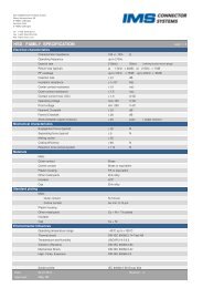
1 Overview - Requirements re. LQP 1, 2 and 3<br />
Step Requirement LQP-1 LQP-2 LQP-3<br />
1 Feasibility study<br />
Form-<strong>CS</strong>-172-Feasibility Statement<br />
Submission: together with offer<br />
2 Estimated capacity<br />
Submission: together with offer<br />
3 Process FMEA<br />
* *<br />
X<br />
X X X<br />
Submission together with initial sample test report * *<br />
4 Control plan<br />
Submission: together with initial sample test report<br />
5 Test equipment capability (gauge R & R)<br />
c g , c gk values for critical dimensions in control plant (SPC, )<br />
Submission: together with initial sample test report<br />
6 Capability of machine/tool (short-term capability)<br />
c m , c mk values for critical dimensions marked with SPC or ; min. 50<br />
parts; (for tool-formed parts: characteristics of soft tool and hard tool)<br />
Submission: together with initial sample test report<br />
7 Initial sample test report with 5 parts, or 1 part per cavity<br />
(for tool-formed parts: characteristics of soft tool and hard tool)<br />
Submission: together with first parts and in the event of changes in the<br />
drawing<br />
8 Material certificate according to ISO 10474 or DIN EN 10204: 3.1B<br />
Submission: together with initial sample test report<br />
9 Material declaration in IMDS<br />
X<br />
X<br />
X<br />
X<br />
X<br />
X<br />
X X X<br />
X X X<br />
Submission: together with initial sample test report * *<br />
10 For coated parts: coating thickness measuring report<br />
Submission: together with initial sample test report<br />
11 Reference samples<br />
Submission: together with EMPB, 5 parts to be stored by supplier<br />
12 Preliminary process capability<br />
p p , p pk values for dimensions marked with;<br />
min. 10 random samples (n = 5) / minimum interval 0.5h<br />
(for tool-formed parts: characteristics of soft tool and hard tool)<br />
Submission: together with initial sample test report<br />
13 Proof of process capability<br />
c p , c pk values for dimensions marked with <br />
50 random samples (n = 5) / min. 50h<br />
Submission in consultation with supplier<br />
14 SPC monitoring / long-term capability analysis<br />
Submission: upon request by IMS-<strong>CS</strong>, within one working day<br />
X required in all cases<br />
* required depending on specifications/arrangements<br />
X<br />
X X X<br />
Instead of the LQP <strong>procedure</strong>s, suppliers may complete Level 3 of the PPAP Procedure<br />
(Production Part <strong>Approval</strong> Process) laid down in the QS 9000 quality standard.<br />
All documents must be submitted in English or German!<br />
X<br />
X<br />
X<br />
X<br />
X<br />
X<br />
X<br />
<strong>RL</strong>-<strong>CS</strong>-<strong>007b</strong>-<strong>Guideline</strong><br />
<strong>Approval</strong> <strong>procedure</strong> <strong>LQP1</strong>-3<br />
Rev. 06 of the 09.12.2009 Page 2 of 20
LQP 1-3 Supplier Quality Planning - Procedures<br />
IMS CONNECTOR SYSTEMS Kft<br />
Ipar Krt. 27.<br />
H-9400 Sopron<br />
Tel +3699-513-508<br />
Fax+3699-513-534<br />
1 <strong>Approval</strong> LQP<br />
If the initial sample test report shows that all dimensions are within the specified limits and<br />
requirements no. 1 to 12 of the LQP are fulfilled, the supplier receives a preliminary approval.<br />
The preliminary approval is included in the initial sample test report form issued by IMS-<strong>CS</strong>.<br />
When all requirements of the LQP are fulfilled, the supplier is granted a series approval. This<br />
approval is issued by IMS-<strong>CS</strong> on the LQP-2 or LQP-3 form respectively (see sample form on<br />
page 4).<br />
IMS has to verify the results of the supplier´s FAI. The minimum requirements are:<br />
- Measuring of all functional and SPC dimensions.<br />
- Measuring of all customer specific and internal specified characteristics<br />
- Attributive evaluation of dirt, damages, burrs, and visual discrepancies<br />
<strong>Approval</strong> by IMS-<strong>CS</strong> does not release the supplier from his responsibility as regards the<br />
quality of the products. The supplier must at all times adhere to all specifications (e.g.<br />
drawings, specifications of materials, forbidden substances, etc.).<br />
During series production, the SPC dimensions must be continuously monitored and the relevant<br />
measured data must be made available to IMS-<strong>CS</strong> upon request. The respective data must be<br />
filed for 5 years and must be accessible to IMS-<strong>CS</strong>. If SPC dimensions are not continuously<br />
monitored during production, the series approval is automatically revoked.<br />
IMS-<strong>CS</strong> reserves the right to carry out process audits, even if series approval has been<br />
granted. The series approval might be revoked, if new requirements arising from the process<br />
audit are not complied with.<br />
If no approval is granted, new samples must be forwarded for the non-compliant dimensions<br />
and/or any missing documents must be submitted. In the event of a reinspection of samples<br />
ordered on the grounds of deviating dimensions, a new initial sample test report must be<br />
compiled, where the non-compliant dimensions are reassessed.<br />
2. When is an LQP required?<br />
A complete or partial LQP <strong>procedure</strong> must be carried out in the following situations:<br />
• New revision index of IMS-<strong>CS</strong> drawing: Steps 7 to 11 (in certain circumstances: steps 4, 5,<br />
12, 13) for the changed dimension(s) or parameter(s). If the revision index is incremented,<br />
new samples must be submitted. If the changes in the drawing don't require a change in<br />
the production <strong>procedure</strong> of the supplier, a simplified <strong>procedure</strong> applies whereby only the<br />
cover page of the initial sample test report form is replaced and completed with the<br />
following details:<br />
- New revision index<br />
- Reason for simplified sampling <strong>procedure</strong> (e.g. no changes in dimensions, does not<br />
concern supplier, packaging instructions are complied with).<br />
• New part: complete LQP must be carried out<br />
• Planned process change: complete LQP must be carried out<br />
• Planned change of material: complete LQP must be carried out<br />
<strong>RL</strong>-<strong>CS</strong>-<strong>007b</strong>-<strong>Guideline</strong><br />
<strong>Approval</strong> <strong>procedure</strong> <strong>LQP1</strong>-3<br />
Rev. 06 of the 09.12.2009 Page 3 of 20
LQP 1-3 Supplier Quality Planning - Procedures<br />
IMS CONNECTOR SYSTEMS Kft<br />
Ipar Krt. 27.<br />
H-9400 Sopron<br />
Tel +3699-513-508<br />
Fax+3699-513-534<br />
• In the event of manufacture of an additional tool for formed parts, steps 6 to 14 must be<br />
completed<br />
• If a tool is replaced by a new one or if a tool is revised, steps 6 to 14 must be completed<br />
• At the change of the machine type, steps 6, 7, 12, 13 and 14 must be completed.<br />
Series parts will not be accepted without prior approval by IMS-<strong>CS</strong>!<br />
<strong>RL</strong>-<strong>CS</strong>-<strong>007b</strong>-<strong>Guideline</strong><br />
<strong>Approval</strong> <strong>procedure</strong> <strong>LQP1</strong>-3<br />
Rev. 06 of the 09.12.2009 Page 4 of 20
LQP 1-3 Supplier Quality Planning - Procedures<br />
IMS CONNECTOR SYSTEMS Kft<br />
Ipar Krt. 27.<br />
H-9400 Sopron<br />
Tel +3699-513-508<br />
Fax+3699-513-534<br />
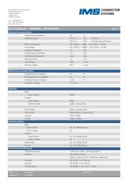
IMS drawing no. Date of issue Rev. IMS purchasing dep. – KLE Phone Fax<br />
Supplier IMS quality – TQT Phone Fax<br />
Supplier sales department Phone Fax<br />
Supplier quality department Phone Fax<br />
No.<br />
Measure<br />
required<br />
1 Feasibility study with<br />
offer<br />
2 Estimated capacity with<br />
offer<br />
3 Process FMEA<br />
4 Control plan<br />
5 Test equipment capability (gauge R&R)<br />
6 Capability of machine / tool (shortterm<br />
capability):<br />
c m, c mk values: dimensions with ◆; 50parts<br />
7 Initial sample test report:<br />
All dimensions and specifications<br />
including material certificates +<br />
reference samples filed by supplier<br />
8 Material certificate according to ISO<br />
10474 or DIN EN 10204:3.1B<br />
9 Material declaration - IMDS<br />
10 Coating-thickness measuring report<br />
11 Reference sample<br />
12 Preliminary process capability:<br />
p p , p pk values: dimensions with ◆<br />
min. 10 random samples (n=5) / min.<br />
interval 0.5h (other intervals after<br />
consultation with IMS)<br />
13 Proof of process capability:<br />
• c p , c pk values: Dimensions with ◆<br />
50 random samples (n=5) / min 50h<br />
• Capacity and frequency of defects<br />
14 SPC monitoring: Dimensions marked with<br />
SPC<br />
Reference sample comp. with series<br />
Comments<br />
Use attached form <strong>CS</strong>-172<br />
Checked<br />
All measures must be completed according to the IMS specifications and requirements.<br />
Signature quality manager of supplier<br />
Date<br />
Series approval for product<br />
Signature IMS-TQT<br />
Date<br />
Comments:<br />
Double border<br />
= to be completed by supplier<br />
Documents regarding items 1 and 2 must be forwarded by the supplier together with the offer to the purchasing<br />
department of IMS Connector Systems. Steps 3 to 14 become only relevant in the event of an order by IMS-<strong>CS</strong>. Send<br />
the completed form together with the order confirmation to the purchasing department of IMS-<strong>CS</strong>.<br />
<strong>RL</strong>-<strong>CS</strong>-<strong>007b</strong>-<strong>Guideline</strong><br />
<strong>Approval</strong> <strong>procedure</strong> <strong>LQP1</strong>-3<br />
Rev. 06 of the 09.12.2009 Page 5 of 20
LQP 1-3 Supplier Quality Planning - Procedures<br />
IMS CONNECTOR SYSTEMS Kft<br />
Ipar Krt. 27.<br />
H-9400 Sopron<br />
Tel +3699-513-508<br />
Fax+3699-513-534<br />
3 The 14 LQP steps<br />
3.1 Feasibility study<br />
Definition<br />
Feasibility study: Examination of the product design in order to establish whether it is suitable<br />
for large-scale series production.<br />
Purpose<br />
• Critical analysis of the suitability of the design for series production<br />
• Systematic communication between supplier and IMS-<strong>CS</strong><br />
• Inclusion of requirements and capabilities of the supplier by ensuring a constructive<br />
dialogue between IMS-<strong>CS</strong> and the supplier<br />
• Support of IMS-<strong>CS</strong> in finding a design that is cost-effective and suitable for its<br />
manufacturing processes<br />
• Ensuring that the series products delivered by the supplier conform to the IMS-<strong>CS</strong><br />
specifications<br />
Requirements<br />
The feasibility study must be documented on form Form-<strong>CS</strong>-172-Feasibility Statement and<br />
forwarded to IMS-<strong>CS</strong>.<br />
The study must include the following information:<br />
• IMS-<strong>CS</strong> drawing number<br />
• Revision index of IMS-<strong>CS</strong> drawing<br />
• Supplier details<br />
• Discussion of feasibility according to Form-<strong>CS</strong>-172<br />
The supplier will inform IMS-<strong>CS</strong> of any design features that might make the production of the<br />
parts difficult, costly or even impossible. In particular, the supplier must examine the specified<br />
dimensions and tolerances.<br />
Examples of common problems to be discussed in a feasibility study:<br />
• Requirements regarding the galvanised coatings (e.g. solderability, etc.)<br />
• Thickness of galvanised coatings ( blind holes, etc.)<br />
• Requirements re. material<br />
• Requirement regarding dimensions of part after hardening<br />
• Requirements regarding measuring<br />
• S dimensions and processing requirements<br />
Submission of feasibility study:<br />
• The feasibility study must be sent to the purchasing department of IMS-<strong>CS</strong> together with the<br />
offer.<br />
• The feasibility study must be completed in English.<br />
• Under point 6 of the Feasability Statement (Form-<strong>CS</strong>-172), (A) must be marked with a<br />
cross. If there is a cross at (B), (C) or (D), IMS-<strong>CS</strong> has to be contacted. If drawings have<br />
changed or in case of other relevant modifications, the feasability analysis has to be<br />
performed again until the result corresponds to the analysis point 6. (A) or it is decided that<br />
the product cannot be produced.<br />
<strong>RL</strong>-<strong>CS</strong>-<strong>007b</strong>-<strong>Guideline</strong><br />
<strong>Approval</strong> <strong>procedure</strong> <strong>LQP1</strong>-3<br />
Rev. 06 of the 09.12.2009 Page 6 of 20
LQP 1-3 Supplier Quality Planning - Procedures<br />
IMS CONNECTOR SYSTEMS Kft<br />
Ipar Krt. 27.<br />
H-9400 Sopron<br />
Tel +3699-513-508<br />
Fax+3699-513-534<br />
3.2 Estimated capacity<br />
Definition<br />
Estimated capacity: Estimation of the secured maximum capacity (number of parts) achievable<br />
by the supplier<br />
Purpose<br />
• Basis for series planning by IMS-<strong>CS</strong><br />
Requirements<br />
The estimated capacity must be entered in form Form-<strong>CS</strong>-166-Capacity in the appendix and<br />
sent to IMS-<strong>CS</strong>. Alternatively, the information can be submitted in any other suitable format.<br />
The declaration of capacity must include the following information:<br />
• IMS-<strong>CS</strong> drawing number<br />
• Revision index of IMS-<strong>CS</strong> drawing<br />
• Supplier details<br />
• Secured maximum capacity per week<br />
• Number of shifts per week<br />
• Earliest date at which capacity is available<br />
Notes<br />
• Standstill times including maintenance periods must be taken into account.<br />
• If the capacity fluctuates, include a respective schedule.<br />
Submission of estimated capacity declaration<br />
• The declaration must be sent to the purchasing dep. of IMS-<strong>CS</strong> together with the offer.<br />
• The estimated capacity declaration must be completed in English.<br />
3.3. Process FMEA (P-FMEA)<br />
Definition<br />
Process FMEA: Risk evaluation and analysis for the entire production process including a<br />
schedule of measures for the elimination of the main risks<br />
Purpose<br />
• Detection and elimination of risk arising in the course of processing<br />
• Preventive modification of the process in order to eliminate faults and defects in the series<br />
production<br />
Requirements<br />
The P-FMEA results must be entered in form Form-<strong>CS</strong>-166-P-FMEA in the appendix and sent<br />
to IMS-<strong>CS</strong>. Alternatively, the information can be submitted in any other suitable format.<br />
The P-FMEA must include the following information:<br />
• IMS-<strong>CS</strong> drawing number<br />
• Revision index of IMS-<strong>CS</strong> drawing<br />
• Supplier details<br />
• Date and revision status of P-FMEA<br />
for each individual process:<br />
• Potential errors<br />
<strong>RL</strong>-<strong>CS</strong>-<strong>007b</strong>-<strong>Guideline</strong><br />
<strong>Approval</strong> <strong>procedure</strong> <strong>LQP1</strong>-3<br />
Rev. 06 of the 09.12.2009 Page 7 of 20
LQP 1-3 Supplier Quality Planning - Procedures<br />
IMS CONNECTOR SYSTEMS Kft<br />
Ipar Krt. 27.<br />
H-9400 Sopron<br />
Tel +3699-513-508<br />
Fax+3699-513-534<br />
• Potential consequences of error<br />
• Potential causes of errors<br />
• Risk priority number (RPN)<br />
• For RPN ≥ 125: recommended measures for the elimination of the risk including details of<br />
person responsible and deadlines<br />
- Measures taken to eliminate risk<br />
- Description of improvements<br />
Notes<br />
• It is often useful to compile the P-FMEA in co-operation with subcontractors or with IMS-<br />
<strong>CS</strong>.<br />
• The P-FMEA must also refer to risks arising during transport and intermediate storage.<br />
Submission of process FMEA<br />
• The P-FMEA must be submitted after the process planning is completed (sequence and<br />
description of individual production processes) and prior to the implementation of the<br />
process. The respective form must be sent to the responsible TQT officer of IMS-<strong>CS</strong><br />
• The process FMEA must be completed in English.<br />
3.4. Control plan<br />
Definition<br />
Control plan: Sequence of all production processes, including testing, from the roll-in of the raw<br />
materials to the dispatch of the goods<br />
Purpose<br />
• Overview of all control and regulation mechanisms governing the process<br />
• Compliance of production process<br />
Requirements<br />
The control plan must be entered in form Form-<strong>CS</strong>-166-Control Plan in the appendix and sent<br />
to IMS-<strong>CS</strong>. Alternatively, the information can be submitted in any other suitable format.<br />
The control plan must include the following information:<br />
• IMS-<strong>CS</strong> drawing number<br />
• Revision index of IMS-<strong>CS</strong> drawing<br />
• Supplier details<br />
• Date and revision status of control plan<br />
• Dimensions and parameters to be used for the assessment of the process capability<br />
for each individual process:<br />
• Description of individual processing steps<br />
• Measured parameter/property<br />
• Specifications / requirements<br />
• Measuring instruments<br />
• Measuring instructions (if applicable)<br />
• Test method (random sampling, 100% testing, SPC testing: type of control card)<br />
• Test frequency (frequency and scope of test <strong>procedure</strong>s)<br />
• Corrective actions, if measured values are outside the specified limits<br />
<strong>RL</strong>-<strong>CS</strong>-<strong>007b</strong>-<strong>Guideline</strong><br />
<strong>Approval</strong> <strong>procedure</strong> <strong>LQP1</strong>-3<br />
Rev. 06 of the 09.12.2009 Page 8 of 20
LQP 1-3 Supplier Quality Planning - Procedures<br />
IMS CONNECTOR SYSTEMS Kft<br />
Ipar Krt. 27.<br />
H-9400 Sopron<br />
Tel +3699-513-508<br />
Fax+3699-513-534<br />
Notes<br />
• The control plan must be regularly updated to reflect the applicable requirements.<br />
Modifications to the control plan are often required after the results of the process<br />
capability analysis (steps 6 and 13) have been obtained.<br />
• Where possible, quality should be controlled rather than inspected.<br />
Submission of control plan<br />
• The control plan must be sent together with the initial sample test report (step 7) to the<br />
responsible TQT officer of IMS-<strong>CS</strong>.<br />
• The control plan must be completed in English.<br />
3.5 Test equipment capability (gauge R&R)<br />
Definition<br />
Test equipment capability: Evaluation of test equipment in order to establish whether the<br />
equipment is suitable for a specific measuring task under industrial conditions whereby<br />
accuracy and repeatability are assessed<br />
Purpose<br />
• Assessment of accuracy of measuring results<br />
• Method to ensure that the results of the process capability assessment are correct,<br />
providing a suitable basis for all further actions<br />
Requirements<br />
The results of the test equipment capability assessment must be entered in forms Form-<strong>CS</strong>-<br />
166-Test equipment capability P.I - P.III in the appendix and sent to IMS-<strong>CS</strong>. Alternatively,<br />
the information can be submitted in any other suitable format.<br />
All test equipment used for the measuring of SPC dimensions or the assessment of the process<br />
capability of the respective part must be individually evaluated.<br />
The assessment must fulfil the following minimum requirements:<br />
• All characteristics must be defined<br />
• The resolution of the measuring instrument must be minimum 5% of the tolerance for the<br />
respective characteristic. The recommended value is 2% of the tolerance for the<br />
characteristic.<br />
• For each measuring instrument, complete first <strong>procedure</strong> 1 followed by <strong>procedure</strong> 2. For<br />
automated testing systems, complete first <strong>procedure</strong> 1 followed by <strong>procedure</strong> 3. Only<br />
testing systems where the parts are automatically fed are considered automated systems.<br />
• Note: Procedure 1 may be completed by the manufacturer of the test equipment (this is<br />
generally the case for standard testing devices).<br />
• Procedure 2 must be completed with the respective measuring instrument at least once for<br />
all dimensions marked with . After consultation with IMS-<strong>CS</strong>, the supplier might be<br />
permitted to examine the equipment using parts and/or dimensions that are similar to that<br />
of the respective product.<br />
• It is however in the interest of the supplier to complete all measurements as laid down in<br />
<strong>procedure</strong> 2.<br />
• Procedure 1: The reference value is 20% of the tolerance for the respective characteristic<br />
and reference 4*s g . The capability indices c g and c gk must be greater than 1.33. c g and c gk<br />
must be calculated on the basis of 25 repeat measurements (recommended). In certain<br />
<strong>RL</strong>-<strong>CS</strong>-<strong>007b</strong>-<strong>Guideline</strong><br />
<strong>Approval</strong> <strong>procedure</strong> <strong>LQP1</strong>-3<br />
Rev. 06 of the 09.12.2009 Page 9 of 20
LQP 1-3 Supplier Quality Planning - Procedures<br />
IMS CONNECTOR SYSTEMS Kft<br />
Ipar Krt. 27.<br />
H-9400 Sopron<br />
Tel +3699-513-508<br />
Fax+3699-513-534<br />
circumstances (and after consultation with IMS-<strong>CS</strong>), it might be sufficient to complete less<br />
than 25 repeat measurements. The minimum number of measurements is however 20.<br />
• The true value of the calibration master must be within the magnitude of the dimensions of<br />
the part to be measured.<br />
• For <strong>procedure</strong> 1, the following data must be submitted (see form Form-<strong>CS</strong>-166-Test<br />
equipment capability P.I):<br />
– Supplier details<br />
– Date of assessment<br />
– Details of measuring equipment (description, model, manufacturer, serial number,<br />
resolution)<br />
– Details of applied references (description, number, actual value)<br />
– Measured values<br />
– Tolerances for characteristics<br />
– c g and c gk<br />
• Procedure 2: Procedure 2 is based on the average range method (ARM). For this<br />
purpose, 10 parts are selected and numbered. The parts are measured twice by one tester<br />
in the same sequence. This <strong>procedure</strong> is repeated by two other testers. Subsequently,<br />
repeatability, reproducibility and the measuring system parameters are calculated (R&R)<br />
The tolerance is used as reference.<br />
• For <strong>procedure</strong> 2, the following data must be submitted (see form Form-<strong>CS</strong>-166-Test<br />
equipment capability P.II):<br />
– Supplier details<br />
– Date of assessment<br />
– Details of measuring equipment (description, model, manufacturer, serial number,<br />
resolution)<br />
– Details of applied references (description, number, actual value)<br />
– Measured values<br />
– Tolerance for characteristics (reference)<br />
– Repeatability (%EV), %Reproducibility (%AV) and measuring system (%R&R)<br />
• Procedure 3: In <strong>procedure</strong> 3, the total %R&R is assessed across the entire range. 25<br />
parts are measured twice in the same sequence, using an automated measuring system.<br />
Subsequently, the repeatability (EV) is calculated. In this case, %EV=%R&R applies, as the<br />
influence of the operator is negligible. The tolerance is used as reference.<br />
• For <strong>procedure</strong> 3, the following data must be submitted (see form Form-<strong>CS</strong>-166-Test<br />
equipment capability P.III):<br />
– Supplier details<br />
– Date of assessment<br />
– Details of measuring equipment (description, model, manufacturer, serial number,<br />
resolution)<br />
– Details of applied references (description, number, actual value)<br />
– Measured values<br />
– Tolerance for characteristics (reference)<br />
– Repeatability (%EV) = measuring system (%R&R)<br />
Notes<br />
• For more detailed information on <strong>procedure</strong>s 1, 2 and 3, please refer to the literature (see<br />
[1], chapter 6).<br />
Submission of test equipment capability (gauge R&R) report<br />
• The report must be sent to the responsible TQT-3 officer of IMS-<strong>CS</strong> together with the initial<br />
sample test report.<br />
• The capability report must be completed in English.<br />
<strong>RL</strong>-<strong>CS</strong>-<strong>007b</strong>-<strong>Guideline</strong><br />
<strong>Approval</strong> <strong>procedure</strong> <strong>LQP1</strong>-3<br />
Rev. 06 of the 09.12.2009 Page 10 of 20
LQP 1-3 Supplier Quality Planning - Procedures<br />
IMS CONNECTOR SYSTEMS Kft<br />
Ipar Krt. 27.<br />
H-9400 Sopron<br />
Tel +3699-513-508<br />
Fax+3699-513-534<br />
3.6 Capability of machine / tool (short-term capability)<br />
Definition<br />
Short-term capability: Method for the assessment of the processing position and variation<br />
Purpose<br />
• Assessment of suitability of the processes and tools applied by the supplier for the relevant<br />
specifications and requirements<br />
• Basis for subsequent process improvements at the hard tool<br />
Requirements<br />
The short-term capacity must be entered in form Form-<strong>CS</strong>-166-Short-term capability in the<br />
appendix and sent to IMS-<strong>CS</strong>. Alternatively, the information can be submitted in any other<br />
suitable format.<br />
The analysis of the short-term capability must fulfil the following minimum requirements:<br />
• All specifications and dimensions marked with in the drawing must be included in the<br />
analysis.<br />
• The dimensions/specifications must be measured/assessed at 50 parts per cavity. The<br />
parts must be individually sampled from the process.<br />
• The head data of the analysis must include the following details:<br />
– IMS-<strong>CS</strong> drawing number<br />
– Revision index of IMS-<strong>CS</strong> drawing<br />
– Supplier details<br />
– Date<br />
– Location of production<br />
• Variable characteristics: For each dimension/specification, the following information must<br />
be included in the analysis:<br />
– c m Histogram<br />
– c mk Nominal value<br />
– Average Upper tolerance limit<br />
– Standard deviation Lower tolerance limit<br />
– Minimum value Measured values<br />
– Maximum value Details of measuring equipment used<br />
• Calculation (normal distribution):<br />
n<br />
1<br />
x = • ∑ xi<br />
n<br />
s =<br />
i = 1<br />
1<br />
−1<br />
• ( x<br />
T = tolerance = UTL − LTL = upper tolerance level − lowertolerance level<br />
c<br />
c<br />
c<br />
c<br />
m<br />
mko<br />
mku<br />
mk<br />
n<br />
T<br />
= (short − termpotential)<br />
6 • s<br />
UTL − x<br />
=<br />
3•<br />
s<br />
x − LTL<br />
=<br />
3•<br />
s<br />
= Minimum<br />
(mean)<br />
n<br />
∑<br />
i=<br />
1<br />
i<br />
− x)<br />
2<br />
(standarddeviation)<br />
{ c , c } (short − term capability)<br />
mko<br />
mku<br />
<strong>RL</strong>-<strong>CS</strong>-<strong>007b</strong>-<strong>Guideline</strong><br />
<strong>Approval</strong> <strong>procedure</strong> <strong>LQP1</strong>-3<br />
Rev. 06 of the 09.12.2009 Page 11 of 20
LQP 1-3 Supplier Quality Planning - Procedures<br />
IMS CONNECTOR SYSTEMS Kft<br />
Ipar Krt. 27.<br />
H-9400 Sopron<br />
Tel +3699-513-508<br />
Fax+3699-513-534<br />
• In general, the calculation of the short-term potential (c m ) and capability (c mk ) must be<br />
based on the normal distribution, as the number of measured values is not sufficient for<br />
any other type of distribution. For position tolerances and certain processes, other<br />
distribution types might be available. In these cases, the normal distribution is not suitable<br />
and indices c m and c mk should therefore be calculated with a different distribution. The<br />
indices must be calculated by means of the percentile method. If another distribution type is<br />
used, please state the reasons.<br />
• Attributive characteristics: The analysis must include the following information (per<br />
attributive characteristic):<br />
– Number of parts within the range of specification<br />
– Number of parts outside the range of specification<br />
– Reasons for deviation from specification<br />
– Method of analysis used<br />
• For the short-term capability analysis of hard tools, the relevant dimensions/specifications<br />
must be measured/assessed at 50 parts per cavity. The parts must be individually sampled<br />
from the process.<br />
Notes<br />
• If required, additional dimensions and specifications may be marked with . This can be<br />
done at the start or during production. These dimensions are then also subject to the above<br />
requirements.<br />
• A separate short-term capability analysis must be completed for each soft tool and hard<br />
tool.<br />
• In the event of modifications to the hard tool, the respective dimensions and specifications<br />
must be reassessed.<br />
Submission of short-term capability analysis<br />
• The short-term capability analysis must be sent to the responsible TQT officer of IMS-<strong>CS</strong><br />
together with the first parts.<br />
• The short-term capability analysis must be completed in English.<br />
3.7 Initial sample test report (EMPB)<br />
Definition<br />
Soft tool initial sample test report: Report including all measured dimensions (with samples) of<br />
the pre-series tool (soft tool)<br />
Hard tool initial sample test report: Report including all measured dimensions (with samples) of<br />
the series tool (hard tool)<br />
Initial sample test report: Report including all measured dimensions (with samples) produced<br />
under serial production conditions<br />
Purpose<br />
• Provision of evidence for the IMS-<strong>CS</strong> engineer that the supplier is capable of producing the<br />
part according to the specifications of IMS-<strong>CS</strong><br />
• The soft tool initial sample inspection report provides the basis for the requirements<br />
regarding the production of series tools (hard tools)<br />
• The soft tool initial sample test report can be used as a reference for possible<br />
improvements to the series tool (hard tool)<br />
• The initial sample test report can be analysed in order to detect systemic errors<br />
<strong>RL</strong>-<strong>CS</strong>-<strong>007b</strong>-<strong>Guideline</strong><br />
<strong>Approval</strong> <strong>procedure</strong> <strong>LQP1</strong>-3<br />
Rev. 06 of the 09.12.2009 Page 12 of 20
LQP 1-3 Supplier Quality Planning - Procedures<br />
Requirements<br />
<strong>RL</strong>-<strong>CS</strong>-<strong>007b</strong>-<strong>Guideline</strong><br />
<strong>Approval</strong> <strong>procedure</strong> <strong>LQP1</strong>-3<br />
IMS CONNECTOR SYSTEMS Kft<br />
Ipar Krt. 27.<br />
H-9400 Sopron<br />
Tel +3699-513-508<br />
Fax+3699-513-534<br />
The initial sample test report must be entered in forms Form-<strong>CS</strong>-166-EMPB in the appendix<br />
and sent to IMS-<strong>CS</strong>. Alternatively, the information can be submitted in any other suitable<br />
format.<br />
The report must fulfil the following minimum requirements:<br />
• Cover page including the following data (Form-<strong>CS</strong>-166-EMPB-Result):<br />
– Address details of supplier<br />
– Type of report<br />
– IMS drawing number, revision index, description of part<br />
– Date of compilation of report<br />
– Number of samples<br />
– Reason for report<br />
– Location of production<br />
– Name and telephone number of person responsible for the report (supplier)<br />
– Signature<br />
– <strong>Approval</strong> section for IMS-<strong>CS</strong><br />
• IMS drawing:<br />
– All dimensions and other specifications (e.g. spring resistance, material specifications,<br />
hardness, optical features, etc.) must be numbered All dimensions/specifications must<br />
be measured/assessed<br />
• Test report including the following data (Form-<strong>CS</strong>-166-EMPB-Test Results):<br />
– The required dimensions/specifications including tolerances must be listed according to<br />
the numbering in the drawing<br />
– For each dimension, all measured values or at least the lowest and highest measured<br />
value must be listed<br />
– Results that are outside the tolerance range must be assessed in co-operation with the<br />
respective engineer. Nonconforming dimensions must be marked accordingly (e.g. with<br />
asterisk, underlined or in bold print) in the initial sample test report and accompanied by<br />
a reference to the discussion with the engineer. After the design engineer has modified<br />
the drawing accordingly, a simplified sampling <strong>procedure</strong> must be completed.<br />
Deviations from this <strong>procedure</strong> have a negative effect on the evaluation of the initial sample<br />
test report and thus on the supplier evaluation.<br />
• Number of parts:<br />
– For tool-formed parts, at least one part per cavity must be measured. The parts must be<br />
clearly identified as to their cavity. All measured parts must be labelled and submitted<br />
together with the test report.<br />
Notes<br />
• The measured parts must be handed over to IMS-<strong>CS</strong> as samples. Parts that have been<br />
cut open to measure an internal dimension must also be submitted.<br />
• In the case of changes to the soft tool or hard tool, or if the process has been modified, the<br />
respective dimensions/specifications must be reassessed with new samples.<br />
• A separate initial sample test report must be completed for each soft tool/hard tool.<br />
• If several parallel machines (processes) are involved in the production, a separate initial<br />
sample test report must be completed for each machine.<br />
• For each measured dimension the used equipment, test <strong>procedure</strong> and personnel<br />
has to be clearly retraceable.<br />
• In the event of a change to the drawing (new revision index of IMS-<strong>CS</strong> drawing), the<br />
modified dimension or parameters must be assessed by means of an initial sample test<br />
report. In certain cases, the simplified sampling <strong>procedure</strong> might be sufficient (see section<br />
2.2).<br />
Rev. 06 of the 09.12.2009 Page 13 of 20
LQP 1-3 Supplier Quality Planning - Procedures<br />
IMS CONNECTOR SYSTEMS Kft<br />
Ipar Krt. 27.<br />
H-9400 Sopron<br />
Tel +3699-513-508<br />
Fax+3699-513-534<br />
• When presenting the Initial Sample Test Report, point 6 (A) of the Feasability Statement<br />
must be marked with a cross (compare paragraph 3.1).<br />
Submission of initial sample test report<br />
• The initial sample test report must be sent to the TQT-department of IMS-<strong>CS</strong> together with<br />
the initial samples. The initial sample test report should reach IMS-<strong>CS</strong> before the first<br />
series parts.<br />
• The initial sample test report must be completed in English.<br />
3.8 Material certificate<br />
Requirements<br />
• Material certificate according to ISO 10474 or DIN EN 10204: 3.1B<br />
Submission of material certificate<br />
• The material certificate must be submitted together with the initial sample test report.<br />
3.9 Material declaration - IMDS<br />
Requirements<br />
The supllier shall follow and confirm the <strong>Guideline</strong>s RoHS 2002/95/EG and RoHS<br />
2002/96/EG and REACH (EG) Nr. 1097/2006.<br />
All relevant data regarding the material of the purchased parts must be recorded in the<br />
International Material Date System (IMDS). For more information, please refer to website<br />
www.mdsystem.com.<br />
Other material declaration formats are only permitted after consultation with IMS-<strong>CS</strong>. The<br />
declaration of must include the following information (Form-<strong>CS</strong>-166-EMPB-Material<br />
Declaration).<br />
- Weight (in grams, rounded to 4 decimals) of purchased parts, including tolerance<br />
- Declaration of materials and their composition<br />
- Information regarding the content of hazardous substances according to German<br />
Chemicals Act / Hazardous Substances Act; CAS code and identification according to<br />
German Hazardous Substances Act, if applicable<br />
- Information regarding the risk of emission of hazardous substances when the material is<br />
handled properly.<br />
- Declaration regarding water-pollutants contained in the material with reference to the<br />
relevant water protection acts<br />
Submission of material declaration<br />
Registration in the IMDS, or declaration in any other agreed format must be made upon<br />
submission of the initial sample test report.<br />
3.10 Galvanised parts<br />
For galvanised, the following samples must be submitted with the initial sample test report:<br />
- 5 raw parts (exception: pre-galvanised strips) and<br />
- 5 galvanised parts<br />
<strong>RL</strong>-<strong>CS</strong>-<strong>007b</strong>-<strong>Guideline</strong><br />
<strong>Approval</strong> <strong>procedure</strong> <strong>LQP1</strong>-3<br />
Rev. 06 of the 09.12.2009 Page 14 of 20
LQP 1-3 Supplier Quality Planning - Procedures<br />
IMS CONNECTOR SYSTEMS Kft<br />
Ipar Krt. 27.<br />
H-9400 Sopron<br />
Tel +3699-513-508<br />
Fax+3699-513-534<br />
The samples must be accompanied by the following information:<br />
- Name of electroplating plant (IMS-<strong>CS</strong> reserves the right to carry out an audit of the<br />
company)<br />
- Structure and composition of galvanised layers [%]<br />
- Galvanised layer thickness report<br />
- Evidence that all requirements of <strong>RL</strong>-<strong>CS</strong>-o6-Definition Surfaces - Supplier are fulfilled<br />
If the supplier changes galvanising subcontractor, he must inform the strategic purchasing<br />
department of IMS-<strong>CS</strong> and resubmit an initial sample test report.<br />
All surfaces must be reinspected.<br />
3.11 Reference samples<br />
For tool-formed LQP-3 parts, the supplier must submit a set of parts (i.e. one part per cavity),<br />
while another set of parts remains at the supplier's premises as reference samples.<br />
For other LQP-3 parts, 5 additional parts must be submitted, while another 5 parts are to be<br />
stored by the supplier as reference samples.<br />
3.12 Preliminary process capability<br />
The preliminary process capability assessment is completed as described in 3.13. The relevant<br />
requirements differ however slightly and are as follows:<br />
• Random samples of n=5 parts must be taken from the process. The minimum interval<br />
between the sampling <strong>procedure</strong>s is 30 minutes (other intervals might be chosen after<br />
consultation with IMS-<strong>CS</strong>). The minimum number of random samples is 10.<br />
• Assessment of P p instead of c p<br />
Assessment of p pk instead of c pk<br />
3.13 Proof of process capability<br />
Definition<br />
Proof of process capability: Analysis of the stability, capabilities and capacities of the supplier<br />
processes. The analysis must cover a minimum production period of 50 hours.<br />
Purpose<br />
• Provision of evidence that the processes of the supplier are stable for a prolonged period of<br />
time and that meet the specifications and capacity requirements.<br />
• Basis of further process improvements<br />
Requirements<br />
The proof of process capability must be entered in forms Form-<strong>CS</strong>-166-Process capability I +<br />
II in the appendix and sent to IMS-<strong>CS</strong>. Alternatively, the information can be submitted in<br />
any other suitable format.<br />
• The process capability must be proven under series conditions.<br />
• All specifications and dimensions marked with in the drawing must be included in the<br />
assessment<br />
• Random samples of n=5 parts must be taken from the process over a period of minimum<br />
50 hours. The minimum number of random samples is 50 (for tool-formed part: take<br />
random samples for all cavities).<br />
<strong>RL</strong>-<strong>CS</strong>-<strong>007b</strong>-<strong>Guideline</strong><br />
<strong>Approval</strong> <strong>procedure</strong> <strong>LQP1</strong>-3<br />
Rev. 06 of the 09.12.2009 Page 15 of 20
LQP 1-3 Supplier Quality Planning - Procedures<br />
<strong>RL</strong>-<strong>CS</strong>-<strong>007b</strong>-<strong>Guideline</strong><br />
<strong>Approval</strong> <strong>procedure</strong> <strong>LQP1</strong>-3<br />
IMS CONNECTOR SYSTEMS Kft<br />
Ipar Krt. 27.<br />
H-9400 Sopron<br />
Tel +3699-513-508<br />
Fax+3699-513-534<br />
• The head data of the analysis must include the following details:<br />
– IMS-<strong>CS</strong> drawing number<br />
– Revision index of IMS-<strong>CS</strong> drawing<br />
– Supplier details<br />
– Date<br />
– Location of production<br />
• Variable characteristics: For each dimension/specification, the following information must<br />
be included in the analysis:<br />
– c p Histogram<br />
– c pk Nominal value<br />
– Average Upper tolerance limit<br />
– Standard deviation Lower tolerance limit<br />
– Minimum value Measured values<br />
– Maximum value Measuring equipment used<br />
– Shewart control card with intervention limits for the assessment of the process stability<br />
• Calculation (normal distribution):<br />
(a) Calculate average and standard deviation of every fifth sample<br />
5<br />
1<br />
x = • ∑ xi<br />
(mean)<br />
5<br />
s =<br />
i = 1<br />
5<br />
1<br />
• ∑(<br />
xi<br />
5 −1<br />
i = 1<br />
− x)<br />
2<br />
(standarddeviation)<br />
(b) Calculate overall average and standard deviation (k = number of samples):<br />
ˆ µ = x =<br />
ˆ σ = s<br />
ges<br />
∑<br />
i=<br />
1<br />
=<br />
k<br />
k<br />
x<br />
k<br />
i<br />
∑<br />
i=<br />
1<br />
k<br />
s<br />
i<br />
1<br />
•<br />
a<br />
n<br />
a5<br />
= 0.940<br />
(c) Assessment of stability: Record averages and standard deviations on a quality control<br />
card. On the average value card, calculate the upper and lower intervention limits. On the<br />
standard deviation card, calculate the upper intervention limit. (Values for 99% intervention<br />
limits, constants for fifth samples)<br />
UIL = x + A • s<br />
LILx<br />
= x − AE<br />
• s<br />
UILs<br />
= BEob<br />
• s<br />
A = 1.152<br />
E5<br />
x<br />
E<br />
BEob5<br />
= 1.927<br />
Criteria for a stable process:<br />
– The values may not be outside the tolerance range<br />
– The total of the values outside the intervention tolerance range (number of values outside<br />
the limits) may not exceed the limits of the spread of the binomial distribution (99%<br />
bilateral)<br />
With 25 random samples, maximum 2 values may be outside the intervention limit (QRK<br />
with intervention limit 99%).<br />
Rev. 06 of the 09.12.2009 Page 16 of 20
LQP 1-3 Supplier Quality Planning - Procedures<br />
IMS CONNECTOR SYSTEMS Kft<br />
Ipar Krt. 27.<br />
H-9400 Sopron<br />
Tel +3699-513-508<br />
Fax+3699-513-534<br />
(d) Calculation of process potential and process capability:<br />
T = Tolerance = UTL − LTL = upper tolerancelimit − lower tolerance limit<br />
c<br />
c<br />
c<br />
p<br />
pko<br />
pk<br />
T<br />
=<br />
6 • s<br />
ges<br />
UTL − x<br />
= ;<br />
3•<br />
s<br />
ges<br />
= Minimum<br />
(potential)<br />
c<br />
pku<br />
{ c , c } (capability)<br />
pko<br />
x<br />
=<br />
3<br />
pku<br />
−<br />
•<br />
LTL<br />
s<br />
ges<br />
• In general, the calculation of the potential (c p ) and capability (c pk ) must be based on the<br />
normal distribution, as the number of measured values and the relatively short period are<br />
not sufficient for any other type of distribution. For position tolerances and certain<br />
processes, other distribution types might be available. In these cases, the normal<br />
distribution is not suitable and indices c p and c pk should therefore be calculated with a<br />
different distribution. The indices must be calculated by means of the percentile method. If<br />
other distribution types are used, please state the reasons. DIN 55219 must be adhered to!<br />
• Attributive characteristics: The analysis must include the following information (per<br />
attributive characteristic):<br />
– Number of parts within the range of specification<br />
– Number of parts outside the range of specification<br />
– Reasons for deviation from specification<br />
– Method of analysis used<br />
• Capacity: The declaration of capacity must include the following information:<br />
– IMS-<strong>CS</strong> drawing number<br />
– Revision index of IMS-<strong>CS</strong> drawing<br />
– Supplier details<br />
– Secured maximum capacity per week<br />
– Number of shifts per week<br />
– Earliest date at which the capacity is available<br />
– Standstill times including maintenance periods must be taken into account<br />
– If the capacity fluctuates, include a respective schedule<br />
Notes<br />
• A separate process capability analysis must be compiled for each machine type/tool.<br />
Exceptions are only permitted if approved by IMS-<strong>CS</strong>.<br />
• If required, additional dimensions and specifications may be marked with . This can be<br />
done at the start or during production. These dimensions are then also subject to the above<br />
requirements.<br />
Submission of proof of process capability<br />
• The proof of process capability must be sent to the responsible TQT officer of IMS-<strong>CS</strong><br />
together with the initial sample test report.<br />
• The proof of process capability must be completed in English.<br />
3.14 SPC monitoring - long-term capability - reference samples<br />
Definition<br />
<strong>RL</strong>-<strong>CS</strong>-<strong>007b</strong>-<strong>Guideline</strong><br />
<strong>Approval</strong> <strong>procedure</strong> <strong>LQP1</strong>-3<br />
Rev. 06 of the 09.12.2009 Page 17 of 20
LQP 1-3 Supplier Quality Planning - Procedures<br />
IMS CONNECTOR SYSTEMS Kft<br />
Ipar Krt. 27.<br />
H-9400 Sopron<br />
Tel +3699-513-508<br />
Fax+3699-513-534<br />
SPC monitoring: Continuous monitoring of the production by means of quality control cards.<br />
For LQP-3 parts, the series must be inspected on a regular basis by comparing the produced<br />
parts with the reference samples. This is necessary to detect whether the product properties<br />
have changed.<br />
Purpose<br />
• Monitoring of production<br />
• During the entire production process, the supplier must ensure that the achieved and<br />
proven process capability is not reduced by rather improved.<br />
• Quick intervention in the event of deviations<br />
Requirements<br />
The proof of SPC monitoring must be submitted upon request by IMS-<strong>CS</strong> only. The details of<br />
the SPC monitoring must be entered in form Form-<strong>CS</strong>-166-SPC monitoring in the appendix<br />
and sent to IMS-<strong>CS</strong>. Alternatively, the information can be submitted in any other suitable<br />
format. The respective data must be filed for 5 years and must be accessible to IMS-<strong>CS</strong>.<br />
• The process must be monitored by means of a parallel set of SHEWART quality control<br />
cards. As a rule, one standard deviation card should be used. In certain special cases (e.g.<br />
manual registration without computer support), the use of a median range card is<br />
permitted.<br />
• The sample must include n=5 parts. In exceptional cases (long measuring periods, the<br />
sample size might be reduced to n=3 parts.<br />
• The interval between the sampling processes depends on the process capability and<br />
stability.<br />
• For all dimensions/specifications that are marked with SPC in the drawing, a separate<br />
quality control card must be completed. In other word, for each marked dimension and<br />
specification, a separate proof of SPC monitoring must be compiled.<br />
• The head data of the analysis must include the following details:<br />
– IMS-<strong>CS</strong> drawing number<br />
– Revision index of IMS-<strong>CS</strong> drawing<br />
– Supplier details<br />
– Period of SPC monitoring<br />
– Location of production<br />
– Measuring equipment used<br />
• Variable characteristics: The following data must be recorded:<br />
– Shewart average card (with intervention limits)<br />
– Shewart standard deviation card (with intervention limits)<br />
– cp and cpk values, calculated over the SPC monitoring period<br />
– Average and standard deviation over the SPC monitoring period<br />
• For the calculation of the intervention limits (normal distribution), total average and total<br />
spread, see 3.11<br />
(a) Intervention limits for average card (probability of non-intervention 99%):<br />
UIL = ˆ µ + A • ˆ; σ LIL = ˆ µ − A • ˆ σ<br />
AE<br />
5<br />
= 1.152 ( n = 5)<br />
E<br />
E<br />
(b) Intervention limits for standard deviation card (probability of non-intervention 99%):<br />
<strong>RL</strong>-<strong>CS</strong>-<strong>007b</strong>-<strong>Guideline</strong><br />
<strong>Approval</strong> <strong>procedure</strong> <strong>LQP1</strong>-3<br />
Rev. 06 of the 09.12.2009 Page 18 of 20
LQP 1-3 Supplier Quality Planning - Procedures<br />
UIL = B<br />
E<br />
ob<br />
• ˆ; σ LIL = B<br />
E<br />
un<br />
• ˆ σ<br />
IMS CONNECTOR SYSTEMS Kft<br />
Ipar Krt. 27.<br />
H-9400 Sopron<br />
Tel +3699-513-508<br />
Fax+3699-513-534<br />
BE<br />
5<br />
= 1.927; B<br />
5<br />
= 0.227<br />
ob<br />
Eun<br />
(c) Assessment of stability: Criteria for a stable process:<br />
– The values may not be outside the tolerance range<br />
– The total of the values outside the intervention tolerance range (number of values outside<br />
the limits) may not exceed the limits of the spread of the binomial distribution (99%)<br />
• Calculation of c p and c pk : see 3.13<br />
• For the calculation of the quality control card and the process capability, a distribution type<br />
that adequately describes the process must be selected. In many cases, a distribution<br />
other than the normal distribution is chosen. If another distribution type is used, please<br />
state the reasons. For all other distribution types, the position must be based on a<br />
SHEWART quality control card with extended limits (mixed distribution) or a Pearson<br />
quality control card (standard distribution, Rayleigh distribution, Pearson distribution,<br />
Johnson transformation, Weibull distribution). Indices cp and c pk must be calculated by<br />
means of the percentile method.<br />
• Attributive characteristics: The following data must be recorded:<br />
– Defects card listing all causes of defects and the number of defects per cause<br />
– Monitoring period<br />
– Frequency of monitoring<br />
Notes<br />
• Other methods of SPC monitoring are only permitted after consultation with IMS-<strong>CS</strong>.<br />
Submission of SPC monitoring report<br />
• Upon request by IMS, submission within two hours (in English).<br />
4 Delivery of series products<br />
Prior to the supply of series products, all documents according to the quality instructions of<br />
IMS-<strong>CS</strong> must be completed, signed and filed with IMS-<strong>CS</strong>. A plating thickness report must be<br />
attached to each delivery of plated parts.<br />
5 Complaints<br />
Complaints must be made in writing on form Form-<strong>CS</strong>-166-8D Report. Alternatively,<br />
complaints might be submitted as an 8D report.<br />
6 Literature<br />
[1] Dietrich, Schulze: Statistical Procedures for Machine and Process Qualification; 1 st edition;<br />
ASQ Quality Press; Milwaukee, Wisconsin; 1999<br />
<strong>RL</strong>-<strong>CS</strong>-<strong>007b</strong>-<strong>Guideline</strong><br />
<strong>Approval</strong> <strong>procedure</strong> <strong>LQP1</strong>-3<br />
Rev. 06 of the 09.12.2009 Page 19 of 20
LQP 1-3 Supplier Quality Planning - Procedures<br />
IMS CONNECTOR SYSTEMS Kft<br />
Ipar Krt. 27.<br />
H-9400 Sopron<br />
Tel +3699-513-508<br />
Fax+3699-513-534<br />
7 Appendix<br />
The appendix consists of a separate document Form-<strong>CS</strong>-166a-Forms-LQP 1 - 3 containing all<br />
forms referred to in this text.<br />
8 List of changes<br />
Rev. 02 from 01.02.2006. replaced by<br />
Rev. 03 from 17.03.2008.<br />
Rev. 04 from 07.04.2008.<br />
Rev. 05 from 29.04.2008.<br />
Rev. 06 from 09.12.2009.<br />
changed: Section 4 - 32 raw parts cancelled<br />
changed: Section 3.10 - 32 raw parts cancelled<br />
changed: Section 4 - plating thickness report added<br />
changed: Section 1 - Elements prefix changed<br />
changed: Section 3.9 – REACH/ROHS added<br />
<strong>RL</strong>-<strong>CS</strong>-<strong>007b</strong>-<strong>Guideline</strong><br />
<strong>Approval</strong> <strong>procedure</strong> <strong>LQP1</strong>-3<br />
Rev. 06 of the 09.12.2009 Page 20 of 20