IOM - King Gage Engineering
IOM - King Gage Engineering
IOM - King Gage Engineering

You also want an ePaper? Increase the reach of your titles
YUMPU automatically turns print PDFs into web optimized ePapers that Google loves.
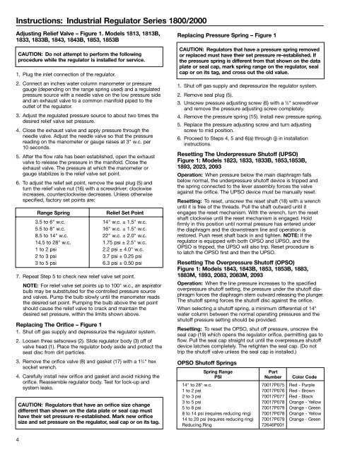
Instructions: Industrial Regulator Series 1800/2000<br />
Adjusting Relief Valve – Figure 1. Models 1813, 1813B,<br />
1833, 1833B, 1843, 1843B, 1853, 1853B<br />
CAUTION: Do not attempt to perform the following<br />
procedure while the regulator is installed for service.<br />
1. Plug the inlet connection of the regulator.<br />
2. Connect an inches water column manometer or pressure<br />
gauge (depending on the range spring used) and a regulated<br />
pressure source with a needle valve on the low pressure side<br />
and an exhaust valve to a common manifold piped to the<br />
outlet of the regulator.<br />
3. Adjust the regulated pressure source to about two times the<br />
desired relief valve set pressure.<br />
4. Close the exhaust valve and apply pressure through the<br />
needle valve. Adjust the needle valve so that the pressure<br />
reading on the manometer or gauge raises at 3" w.c. per<br />
10 seconds.<br />
5. After the flow rate has been established, open the exhaust<br />
valve to release the pressure in the manifold. Close the<br />
exhaust valve. The pressure at which the manometer or<br />
gauge stabilizes is the relief valve set point.<br />
6. To adjust the relief set point, remove the seal plug (5) and<br />
turn the relief valve nut (16) with a screwdriver; clockwise<br />
increases, counterclockwise decreases. Unless otherwise<br />
specified, factory set points are:<br />
Range Spring<br />
Relief Set Point<br />
3.5 to 6" w.c. 14" w.c. ± 1.5" w.c.<br />
5.5 to 8" w.c. 16" w.c. ± 1.5" w.c.<br />
8.5 to 14" w.c. 22" w.c. ± 2.0" w.c.<br />
14.5 to 28" w.c. 1.75 psi ± 2.5" w.c.<br />
1 to 2 psi 2.2 psi ± 4.0" w.c.<br />
2 to 3 psi 3.7 psi ± 0.25 psi<br />
3 to 5 psi 6.3 psi ± 0.50 psi<br />
7. Repeat Step 5 to check new relief valve set point.<br />
NOTE: For relief valve set points up to 100" w.c., an aspirator<br />
bulb may be substituted for the controlled pressure source<br />
and valves. Pump the bulb slowly until the manometer reads<br />
the desired set point. Pumping the bulb above the set point<br />
should cause the relief valve to crack and maintain the<br />
desired set pressure, within the limits shown above.<br />
Replacing The Orifice – Figure 1<br />
1. Shut off gas supply and depressurize the regulator system.<br />
2. Loosen three setscrews (2). Slide regulator body (3) off of<br />
valve head (1). Place the regulator body aside and protect the<br />
seat disc from dirt particles.<br />
3. Remove the orifice valve (8) and gasket (17) with a 1 3 ⁄4" hex<br />
socket wrench.<br />
4. Carefully install new orifice and gasket and avoid nicking the<br />
orifice. Reassemble regulator body. Test for lock-up and<br />
system leaks.<br />
CAUTION: Regulators that have an orifice size change<br />
different than shown on the data plate or seal cap must<br />
have their set pressure re-established. Mark new orifice<br />
size and set pressure on the regulator, seal cap or on its tag.<br />
Replacing Pressure Spring – Figure 1<br />
CAUTION: Regulators that have a pressure spring removed<br />
or replaced must have their set pressure re-established. If<br />
the pressure spring is different from that shown on the data<br />
plate or seal cap, mark spring range on the regulator, seal<br />
cap or on its tag, and cross out the old value.<br />
1. Shut off gas supply and depressurize the regulator system.<br />
2. Remove seal plug (5).<br />
3. Unscrew pressure adjusting screw (6) with a 3 ⁄8" screwdriver<br />
and remove the pressure adjusting screw completely.<br />
4. Remove the pressure spring (15). Install new pressure spring.<br />
5. Replace the pressure adjusting screw and turn adjusting<br />
screw to mid position.<br />
6. Proceed to Steps 4, 5 and 6(a) through (j) in installation<br />
instructions.<br />
Resetting The Underpressure Shutoff (UPSO)<br />
Figure 1: Models 1823, 1833, 1833B, 1853,1853B,<br />
1893, 2023, 2093<br />
Operation: When pressure below the main diaphragm falls<br />
below normal, the underpressure shutoff device is tripped and<br />
the spring connected to the lever assembly forces the valve<br />
against the orifice. The UPSO device must be manually reset.<br />
Resetting: To reset, unscrew the reset shaft (18) with a wrench<br />
until it is free of the threads. Pull the shaft outward until it<br />
engages the reset mechanism. With the wrench, turn the reset<br />
shaft clockwise until the reset mechanism is engaged. Hold<br />
firmly in this position until normal pressure has entered under<br />
the diaphragm and the downstream line and operation is<br />
restored. Push reset shaft back in and tighten. NOTE: If the<br />
regulator is equipped with both OPSO and UPSO, and the<br />
OPSO is tripped, the UPSO will also trip. Reset procedure is<br />
to latch the OPSO first and then the UPSO.<br />
Resetting The Overpressure Shutoff (OPSO)<br />
Figure 1: Models 1843, 1843B, 1853, 1853B, 1883,<br />
1883M, 1893, 2083, 2083M, 2093<br />
Operation: When the line pressure increases to the specified<br />
overpressure shutoff setting, the pressure under the shutoff diaphragm<br />
forces the diaphragm stem outward releasing the plunger.<br />
The shutoff spring forces the shutoff disc against the orifice.<br />
When selecting a shutoff spring, a minimum differential of 14"<br />
water column between the normal operating pressures and the<br />
shutoff pressure setting should be provided.<br />
Resetting: To reset the OPSO, shut off pressure, unscrew the<br />
seal cap (19) which opens the regulator orifice, permitting gas to<br />
flow. Pull the seal cap straight out until the overpressure shutoff<br />
device latches completely. The retighten the seal cap. (Do not<br />
trip the shutoff valve unless the seal cap is installed.)<br />
OPSO Shutoff Springs<br />
Spring Range<br />
Part<br />
PSI Number Color Code<br />
14" to 28" w.c. 70017P075 Red - Purple<br />
1 to 2 psi 70017P076 Red - Brown<br />
2 to 3 psi 70017P077 Red - Black<br />
3 to 5 psi 70017P078 Orange - Yellow<br />
5 to 8 psi 70017P079 Orange - Green<br />
8 to 14 psi (requires reducing ring) 70017P078 Orange - Yellow<br />
14 to 20 psi (requires reducing ring) 70017P079 Orange - Green<br />
Reducing Ring<br />
72646P001<br />
4