AXIAL FLOW VALVES
AXIAL FLOW VALVES
AXIAL FLOW VALVES
- No tags were found...

Create successful ePaper yourself
Turn your PDF publications into a flip-book with our unique Google optimized e-Paper software.
SB9509.3<strong>AXIAL</strong> <strong>FLOW</strong><strong>VALVES</strong>
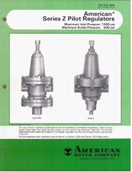
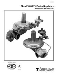
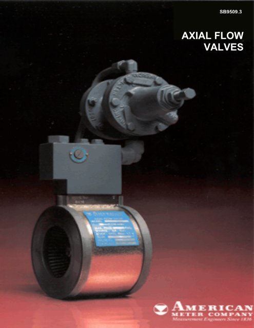
The improved technology for pressure regulationThe integral manifold blockThe American Axial Flow Valve provides pressure and flowcontrol in high capacity pipelines. It can be used for pressureregulation, overpressure relief, flow control or simply as anon/off valve.The AFV is unique in that there is no mechanical connection tothe control element. Instead, the valve uses an elastomersleeve which expands or contracts depending on the pressuredifferential across this sleeve. This principle provides a valvethat is extremely compact and lightweight, easy to install andservice, and one with a streamlined flow path for quietoperation. Because of its V-shaped design, the sleeve in anAmerican Axial Flow Valve can be reversed for extendedservice life. This design also causes the sleeve to expandaround its entire circumference, producing lower stresses for agiven opening. The excellent flexibility of the sleeve materialand the double sealing surfaces in the American designcombine to provide a positive lockup characteristic for the valve.Standard sleeve materials provide a wide working temperaturerange and excellent resistance to abrasion and swelling. Theyare field-proven in a variety of installations involving natural gasservice. Specialized sleeve materials are also available forapplications involving extreme temperatures, where chemicalresistance is needed and for specialized services such as waterscarfing.American Axial Flow Valves install between the flanges ofstandard pipelines. Series 300 valves have a maximumworking pressure of 720 psig and are available for 2”, 3”, 4”, 6”,8” and 12” pipelines. Series 600 valves, with a maximumworking pressure of 1440 psig, are available in 2”, 4”, 6” and 8”sizes.Depending on the particular pilot used, the AFV can regulateoutput pressures from inches W.C. up to 600 psig. Higherpressures can be regulated with an instrument controller inplace of a pilot. It can therefore be used to provide primary andsecondary pressure cuts in a variety of transmission,distribution and industrial applications.With the standard elastomer sleeve, the American Axial FlowValve has an operating temperature range from –20 to 150°F.All components exposed to the flow path are fabricated ofabrasion and corrosion resistant materials.incorporates a variablerestrictor between the inletpressure port and controlpressure port. Low settingsprovide a smaller orifice andquick opening and slowerclosing of the valve. Highersettings, with their largerorifices, provide sloweropening, quicker closingcharacteristics.
Basic valve operationBecause there is no mechanical connection to the control element, there’s noworry about shaft sealing. Except for the valve inlet and outlet, the onlyconnections to the Axial Flow Valve are three pneumatic lines to the manifold:inlet pressure, control pressure and exhaust / downstream bleed. The valveresponds to the difference in pressure between the inlet port and the controlport. The different functions of the valve) downstream regulation, relief, etc.)are determined by the type pf external pilot and the piping of the pilot. Theoperating characteristics of the valve (fast opening, slow closing, etc.) aredetermined by the setting of the adjustable restrictor in the manifold.Closed position Throttling position Full open positionInlet pressure is applied to the innersurface of the sleeve in theupstream section of the valve andcontrol pressure is applied to theexterior of the sleeve. Because thesleeve is slightly smaller in diameterthan the cage, when inlet andcontrol pressure are equal thesleeve preload keeps the valveclosed.As control pressure is reduced,the inlet pressure overcomes thepreload and begins to force thesleeve away from the inlet cage.As the sleeve continues toexpand, a portion of thedownstream cage is uncoveredand flow begins through thevalve. When downstreamdemand is satisfied, the balancedforces on either side of the sleevemaintain it in an equilibriumposition.When fully opened, thedownstream cage is completelyexposed and the sleeve isexpanded to the point where it issupported against the inner bodyof the valve. Since the controlpressure is usually aspiratedthrough the downstream bleedport, the control pressure issignificantly lower thandownstream pipeline pressure athigh flow rates. This minimizesthe differential between inlet andoutlet required for full valveopening.
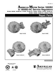
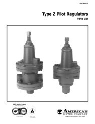
Pilot regulatorsThese spring-loaded regulators are used to balancethe pressure applied to the control port of an AxialFlow Valve. It is actually the choice of pilot thatdetermines function (pressure reduction orbackpressure) and output pressure or relief setting.The adjustable restrictor which is an integral part ofthe AFV determines operating characteristics; lowsettings for quick opening and slow closing, highersettings for slow opening and quick closing.Types ZCS-150 and ZSC-320-150These double diaphragm regulatorsare for backpressure or pressurerelief applications. The ZSC-150provides setpoints from 1 to 225 psi,while the ZSC-320-150 has a rangeof 200 to 600 psi.Types ZSC-100 and ZSC-320-100Both of these models are doublediaphragm regulators for pressurereducing applications. The ZSC-100supplies output pressures from 1 325psi; the ZSC-320-100 has an outputrange of 200 to 600 psi.Type 1203This family of regulators isfor pressure reducingservice requiring outputpressures from 5 inchesW.C. to 5 psi.Spring force tends to hold the regulator open.This force is counterbalanced by pressureapplied to the downstream sensing chamberdiaphragm. When the downstream pressuredecreases, the regulator is opened wider,increasing flow. This produces a larger dropacross the restrictor and a decrease in controlpressure to the AFV, thereby increasing flow tosatisfy downstream demand.As long as the spring force is greater than theforce of the upstream pressure acting on theupstream sensing chamber diaphragm, theregulator is held closed. When upstreampressure increases beyond the setpoint, theregulator opens. Since the exhaust isnormally at close-to-zero pressure, a largeflow occurs through the regulator, quicklyopening the AFV to relieve the overpressurecondition.
ApplicationsSingle-stage pressure reduction. Whendownstream pressure decreases, spring forceincreases the effective opening of the pilot. Theincrease in flow produces a larger pressure dropacross the variable restrictor, reducing controlpressure to the AFV and increasing flow in theline.Tow-stage pressure reduction: psi to psi to in.W.C. When large reductions in pressure arerequired, the cut can be made in two stages.Here an American AFV and Type ZSC-100 pilotcontrol a psi to psi cut. The second stageincorporates a Type 1203 regulator to give a finaloutput pressure in the inches W.C. range.
Pressure reduction with monitor. Duringnormal operation, a single AVF, the worker,performs the pressure cut. The monitoring pilot isset at an output pressure slightly higher than theworking pilot. Since the monitoring pilot is alwaysopen, the monitor AFV is held in the full openposition. If a malfunction occurs on the workerside, the output pressure rises to the monitorsetpoint and it assumes control. The roles ofworker and monitor can be reversed by simplyresetting the pilots.Two-stage regulators with monitor override.Under normal conditions, both AFV’s areperforming pressure cuts. However, they aresized so either one can handle the entire cut in theevent of a malfunction. If a problem occurs in the1st stage, P2 increases and the 2nd stage makesa correspondingly larger cut. If the 2nd stagemalfunctions, P3 increases and the override pilotassumes control of the 1st stage AFV, causing itto take a larger single stage pressure cut. Themaximum interstage pressure, P2, is limited to themaximum spring adjustment of the 1st stage pilot–325 psi for the SZC or 600 psi for the ZSC-320.
Pressure relief valve. With the ZSC-150 pilot,the AFV is closed as long as upstream pressureis below the setpoint. Because the exhaust portis normally at atmosphere, once the regulatoropens, a large drop occurs across the restrictor,causing the AFV to open quickly.On/off control of flow in a pipeline. When theelectrically operated valve is open, the inputpressure is bled downstream causing a dropacross the restrictor. Since the control pressureis less than the input pressure, the AFV opensto allow flow in the pipeline. Closing theelectrically operated valve causes the controlpressure to build up to the input pressure,closing the AFV.
ApplicationsUnderpressure shutoff. As long as thedownstream pressure is above the setpoint, thepilot is held open causing a drop across therestrictor and allowing the valve to remain open.If downstream pressure decreases below thesetpoint, the pilot is forced closed and inletpressure is applied to the control port of theAFV, equalizing the pressure across the sleeveand closing the valve. The needle valve is usedto start up and reset the system. With Valve Aopen, there is a pressure drop across therestrictor, allowing the AFV to open. Once thedownstream system is pressurized, close valveA.Pressure regulation with instrumentcontroller. To overcome the limitations ofspring-loaded regulators, the AFV can be usedas the final control element with a pressurecontroller and a small diaphragm motor valve.Among the advantages are overcoming springdroop, responding to the rate of change indownstream demand and the ability to regulatepressures above 600 psig (up to 1440 psig).
Regulation with check valve in alternatefeed line. In this application, gas is suppliedto a process line at 550 psi. Two AFV’s inparallel are used to reduce the supplypressure and combine it with the output of anLNG plant for other uses within the facility.During normal operation, AFV #2 is heldclosed since the control pressure (550 psi) ishigher than the normal outlet pressure (300psi).If there is a disruption in the normal gassupply, valves #1 and #3 are closed whileAFV #2 goes full open. Under theseconditions, the facility can continue to operatethe process line, at a reduced rate, using thelower pressure LNG supply.
Sizing the American AFVfor pressure reducing serviceTo properly size an axial flow valve for a pressure regulationapplication, three parameters are needed:□ the maximum flow rate through the valve in MSCFH□ the pressure range at the inlet in psig□ the controlled, or regulated pressure at the outlet in psigAs an example, consider an application with a maximum expectedflow rate of 2000 MSCFH, an inlet pressure range of 275 to 300psig and a desired outlet pressure of 125 psig. The fluid is naturalgas, 0.6 gravity, 14.73 psia, 60°F base.MinimumMaximumAFV SleeveSerie Number Cracking Full Open Continuous Intermittents300 H-5L * 1.5 psid 5 psid 30 psid 50 psid300 H-5 3.5 psid 15 psid 125 psid 180 psid300 H-7 14 psid 30 psid 500 psid 720 psid600 B-7 30 psid 60 psid 1000 psid 1440 psid1.Determine the maximum differential pressure across the valveand use this value to select the appropriate sleeve. Specificationson standard sleeves are as shown below.3.Select a pilot with a spring suitable for the desired set point usingPilot Type Outlet Pressure Part Number1 to 5 psi 71411P010ZSC-100AndZSC-1502 to 10 psi 71411P0433 to 30 psi 71411P01110 to 75 psi 71411P01225 to 150 psi 71411P014100 to 225 psi 71411P009ZSC-320-100200 to 600 psi 71421P008ZSC-320-1505 to 9” W.C. 70017P00112039 to 15” W.C. 70017P002(125 psig max.14” W.C. to 2 psi 70017P073inlet pressure)2 to 5 psi 70017P078the lowest outlet pressure range covering the set point.4.Determine the outlet pipe size required to maintain the 200 ft/seclimits commonly used in the gas industry:D=2 QP 2*2”, 3”, 4” and 6” sizes onlyIn this case, the maximum differential is 300 – 125 = 175 psid andthe H-7 sleeve will be required.2.Using the valve capacity tables from American Meter, select theappropriate valve size based on the lowest inlet pressure. Thetables show capacity with the valve fully open. It is good practice tosize the valve based on 75% of the maximum capacity to allow forvariations in piping, pilots, etc.In the example, this value would be:Where: D = outlet pipe diameter (inches)Q = flow rate (MSCFH)P 2 = downstream pressure (psia)In our example,D=2 3276= 9.684”125 + 14.732000 MSCFH = MSCFCH0.75From the capacity table, a six inch Series 300 valve, with an inletpressure of 275 psig has a maximum capacity of 3279 MSCFH at100 psig outlet and 3273 MSCFH at 150 psig outlet. Interpolatingfor an outlet pressure of 125 psig shows a maximum capacity of3276 MSCFH, sufficient for the application.Therefore, the outlet of the 6” AFV should be expanded to a 10”pipe using 15” cones at the outlet or within 5d(30”) of the outlet.The sensing tap should be 5d to 8d downstream of the valve orcone outlet. The smaller the valve size, the more critical the needfor expanding the outlet piping in order to achieve the full capacityof the valve.When using two similar size AFV’s in series, such as a monitor andworker, size should be based on 71% of the maximum values in thecapacity table before applying the 75% allowance for variations.
Sizing the American AFVfor pressure relief serviceWhen sizing an AFV for relief services, it’s necessary todetermine the allowable pressure rise above the set(relief) point and to assure that the relief valve has acapacity that is large enough to fully discharge the opencapacity of the control (working) regulator). Generallythe relief valve will be one or two sizes larger than theworking regulator.A typical situation might be an application using a 3 inchSeries 300 AFV with a ZSC-100 pilot as an operatingregulator. The inlet pressure to the worker is 75 to 150psig and the worker is set at 50 psig. Maximum flow rateis 654 MSCFH, based on 150 psi maximum inletpressure. The maximum allowable operating pressure is60 psig, and the maximum pressure buildup above therelief point is 6 psig.Other parameters necessary to obtain the full reliefcapacity are:□ pilot downstream bleed should be connected to the AFVaspirator port□ restrictor setting should be 3 or less consistent withstability and speed of opening□ the upstream sensing line tap should be 2d to 3d fromthe inlet of the AFV1.Determine the range and type pf control pilot operator.60 psig MAOP + 6 psig max buildup = 66 psigFrom the pressure spring table, select a ZSC-150 pilot(backpressure type) with spring 71411P012 (10 to 75psig). The pressure buildup above the setpoint is 5% ofthe maximum of the spring range, in this case 0.05 X 75= 3.5 psig. (This is a characteristic of the ZSC-150 withthe standard 3/32” orifice as used with AFV’s)2.Determine the maximum relief valve setting, maximumpermitted line pressure minus pressure buildup.66 psig – 3.75 psig = 62.25 psig3.Establish the size of the relief valve using 644 MSCFHand the maximum permitted line pressure of 66 psig.Using the capacity tables find the smallest valve that willdischarge 654 MSCFH at 66 psig inlet pressure and 0psig outlet pressure. The 66 psig inlet pressure willrequire interpolation.A 4 inch valve has a capacity of 548 MSCFH. While thiscapacity is too small, this type pf situation might justify acloser look at the specified 644 MSCFH for economicreasons.If the 654 MSCFH is validated, a 6 inch American AFVwill discharge 980 MSCFH. To fully realize the reliefcapacity of the AFV, the discharge should be toatmosphere or nor more than 5d of equivalent pipe at theoutlet. If outletpiping is required in excess of 100 ft/sec,the relieved gas generates excessive reactive forces andthe relief system must be supported.
The Bulletins listed here provide additional information on American Axial Flow Valves. Copies can berequested from your nearest sales office, or by contacting the American Meter home office.! Axial Flow Valve Accessories – Descriptive Bulletin SB 9525! Low differential Pressure Axial Flow Valves – Descriptive Bulletin 9520! Axial Flow Valve Capacity Tables – Technical Data Bulletin 9610! Axial Flow Valve Operation & Installation – Descriptive Bulletin 9710! Series Z Pilot Regulators – Descriptive Bulletin 8545! Series 1200 Regulator – Descriptive Bulletin 8505