AXIAL FLOW VALVES
AXIAL FLOW VALVES
AXIAL FLOW VALVES
- No tags were found...

You also want an ePaper? Increase the reach of your titles
YUMPU automatically turns print PDFs into web optimized ePapers that Google loves.
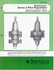
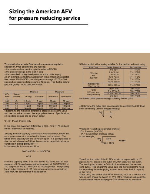
Sizing the American AFVfor pressure reducing serviceTo properly size an axial flow valve for a pressure regulationapplication, three parameters are needed:□ the maximum flow rate through the valve in MSCFH□ the pressure range at the inlet in psig□ the controlled, or regulated pressure at the outlet in psigAs an example, consider an application with a maximum expectedflow rate of 2000 MSCFH, an inlet pressure range of 275 to 300psig and a desired outlet pressure of 125 psig. The fluid is naturalgas, 0.6 gravity, 14.73 psia, 60°F base.MinimumMaximumAFV SleeveSerie Number Cracking Full Open Continuous Intermittents300 H-5L * 1.5 psid 5 psid 30 psid 50 psid300 H-5 3.5 psid 15 psid 125 psid 180 psid300 H-7 14 psid 30 psid 500 psid 720 psid600 B-7 30 psid 60 psid 1000 psid 1440 psid1.Determine the maximum differential pressure across the valveand use this value to select the appropriate sleeve. Specificationson standard sleeves are as shown below.3.Select a pilot with a spring suitable for the desired set point usingPilot Type Outlet Pressure Part Number1 to 5 psi 71411P010ZSC-100AndZSC-1502 to 10 psi 71411P0433 to 30 psi 71411P01110 to 75 psi 71411P01225 to 150 psi 71411P014100 to 225 psi 71411P009ZSC-320-100200 to 600 psi 71421P008ZSC-320-1505 to 9” W.C. 70017P00112039 to 15” W.C. 70017P002(125 psig max.14” W.C. to 2 psi 70017P073inlet pressure)2 to 5 psi 70017P078the lowest outlet pressure range covering the set point.4.Determine the outlet pipe size required to maintain the 200 ft/seclimits commonly used in the gas industry:D=2 QP 2*2”, 3”, 4” and 6” sizes onlyIn this case, the maximum differential is 300 – 125 = 175 psid andthe H-7 sleeve will be required.2.Using the valve capacity tables from American Meter, select theappropriate valve size based on the lowest inlet pressure. Thetables show capacity with the valve fully open. It is good practice tosize the valve based on 75% of the maximum capacity to allow forvariations in piping, pilots, etc.In the example, this value would be:Where: D = outlet pipe diameter (inches)Q = flow rate (MSCFH)P 2 = downstream pressure (psia)In our example,D=2 3276= 9.684”125 + 14.732000 MSCFH = MSCFCH0.75From the capacity table, a six inch Series 300 valve, with an inletpressure of 275 psig has a maximum capacity of 3279 MSCFH at100 psig outlet and 3273 MSCFH at 150 psig outlet. Interpolatingfor an outlet pressure of 125 psig shows a maximum capacity of3276 MSCFH, sufficient for the application.Therefore, the outlet of the 6” AFV should be expanded to a 10”pipe using 15” cones at the outlet or within 5d(30”) of the outlet.The sensing tap should be 5d to 8d downstream of the valve orcone outlet. The smaller the valve size, the more critical the needfor expanding the outlet piping in order to achieve the full capacityof the valve.When using two similar size AFV’s in series, such as a monitor andworker, size should be based on 71% of the maximum values in thecapacity table before applying the 75% allowance for variations.