Angstrom Thermal Evaporation Chamber - Unit's home page.
Angstrom Thermal Evaporation Chamber - Unit's home page.
Angstrom Thermal Evaporation Chamber - Unit's home page.

You also want an ePaper? Increase the reach of your titles
YUMPU automatically turns print PDFs into web optimized ePapers that Google loves.
<strong>Angstrom</strong> <strong>Thermal</strong> <strong>Evaporation</strong> <strong>Chamber</strong><br />
Standard Operating Procedure<br />
Holmes Research Group<br />
9/16/09<br />
Purpose:<br />
This document provides guidelines on how to properly operate and maintain the <strong>Angstrom</strong><br />
Engineering thermal evaporation chamber in Amundson 423.<br />
(A) <strong>Chamber</strong> Control Software Operation:<br />
Overview:<br />
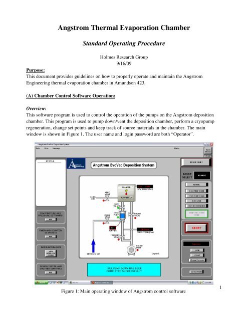
This software program is used to control the operation of the pumps on the <strong>Angstrom</strong> deposition<br />
chamber. This program is used to pump down/vent the deposition chamber, perform a cryopump<br />
regeneration, change set points and keep track of source materials in the chamber. The main<br />
window is shown in Figure 1. The user name and login password are both “Operator”.<br />
Figure 1: Main operating window of <strong>Angstrom</strong> control software<br />
1
Venting Deposition <strong>Chamber</strong>:<br />
In order to vent the deposition chamber to atmospheric pressure, click on the “Auto Vent” button on<br />
the main window. A new window will appear, click “Start”. The chamber will automatically vent to<br />
atmospheric pressure. This process will take around 10 minutes when venting from chamber base<br />
pressure.<br />
Pumping Down Deposition <strong>Chamber</strong>:<br />
In order to pump down the deposition chamber, click on the “Full Pump Down” button on the main<br />
window. The chamber will automatically keep pumping until the cycle is changed. There is an<br />
interlock in the software that will not allow a deposition to occur until the chamber pressure has<br />
reached 8x10 -7 Torr. A typical pump down from atmospheric pressure to this interlock will take<br />
around 15 minutes.<br />
Cryopump Regeneration:<br />
This cycle is only to be performed when necessary, as the temperature of the cryopump increases to<br />
over 15K, or as needed. When this process is selected, the temperature and pressure of the<br />
cryopump will be elevated to remove any trapped gases from the cooling element. The process is<br />
automated to go through three cycles that flush out the pump and restore it to original operating<br />
condition.<br />
Source Detail and Shutter Controls:<br />
This window (Figure 2) is used to keep track of the source materials currently in the deposition<br />
chamber. Every time a material is replaced this window must be updated. This window is also used<br />
to enable/disable substrate heating, substrate rotation and to control the shutter inside the chamber.<br />
2
Figure 2: Source detail and shutter controls software window<br />
(B) Boat Positioning and Replacement:<br />
Boat Types for <strong>Chamber</strong> Materials:<br />
For different materials, we use a variety of boats. As a general rule, baffled boats are used for<br />
organic materials, dimple boats are used for metals (besides aluminum) and LiF, and wire baskets<br />
are used for aluminum. The boats used are ordered from R.D. Mathis Company. New boats should<br />
be ordered when the supply is getting low to ensure that the next few users do not run out. See<br />
Figure 3 below for the boats used and the corresponding model numbers for each boat.<br />
3
Baffled boat for organic materials, R.D. Mathis catalog # SB-6 and SB-6a<br />
Tungsten wire basket for Al deposition, R.D.<br />
Mathis catalog # B12A-3x.030W<br />
Tungsten dimple boats for metal and LiF<br />
deposition, R.D. Mathis catalog #S9C-.010W<br />
Modified to 3.5 inches long<br />
Figure 3: Boat types and ordering information<br />
Boat Placement:<br />
To reduce contamination the following material placement should always be used:<br />
Source 1: Al<br />
Source 2: LiF, Ag, Au<br />
Source 3: BCP, BPhen, Alq<br />
Source 4: TAZ, Blockers<br />
Source 5: TPP, TCTA, TAZ, Hosts<br />
Source 6: Donors: CuPc, SubPc, etc.<br />
Source 7: Phosphors: FIrpic, Irppy, PtOEP, etc.<br />
Source 8: Acceptors: C 60<br />
If a new material is being placed in the chamber, consult other group members as well as Professor<br />
Holmes to ensure proper placement of that material.<br />
4
Replacing boats:<br />
Each source has a set two posts and clamps that hold the ends of a boat. To replace boats, simply<br />
unscrew the wing nuts to loosen the clamps until you can pull the boat out. Re-usable boats should<br />
be placed in aluminum foil and put away in their appropriate tray (the trays are labeled for all of the<br />
materials in the chamber). Aluminum boats should be removed from the box and thrown away.<br />
Slide the new boat into the clamps and tighten the wing nuts down. Make sure the boat is centered<br />
in the clamps, otherwise it may get deformed and you may have poor electrical contact.<br />
Replacing foil:<br />
Between each source there are shields which help to prevent contamination between sources. Each<br />
shield needs to be wrapped in foil to prevent material from depositing on the shields. In addition,<br />
each time a material is switched, the foil on the shields adjacent to that source and the foil<br />
underneath need to be replaced to prevent contamination. To replace the foil, slide the shield off of<br />
its mounting bracket. Remove the old foil from the shield and from the glovebox. Place the new<br />
foil on the shield making certain every bit of the shield is covered. Then proceed to slide the shield<br />
back on to its mounting bracket. Make sure that the foil is tight to the shield and not obstructing the<br />
deposition.<br />
(C) Deposition Control Software Operation:<br />
Overview:<br />
The SQS-424 software is used to control the deposition of thin films in the <strong>Angstrom</strong> deposition<br />
chamber. This software has three basic deposition modes: manual mode, automatic rate-controlled<br />
mode, and automatic percent power controlled mode. This software displays information about the<br />
current rate (Å/s), thickness (kÅ), power level (%), and quartz crystal monitor (QCM) lifetimes (%)<br />
(see Fig. 4). The username for this software is “Super” (there is no password so leave it leave<br />
blank).<br />
5
Figure 4: Deposition software main screen<br />
Setting up a new material:<br />
Before a deposition can be done with a new material, several program parameters must be defined.<br />
First, under “Edit” “Material” a material profile must be defined. This profile includes the<br />
material name (i.e. “Aluminum”), the material density (1.1 for most organic materials), and Z factor<br />
(1 for most organics); when finished editing, close the box to save the material profile.<br />
Next, under “Edit” “Films” create a “New” film, enter the film name with the material followed<br />
by the source, (i.e. BCP Src 3). Several entries must be made to define the film:<br />
Deposit: P: 100<br />
I: 10<br />
D: 0<br />
Shutter Delay:<br />
“Enabled”<br />
Accuracy: 20%<br />
Wait: 60 seconds<br />
Hold: 3 seconds<br />
6
Rate Sampling:<br />
“Continuous”<br />
Accuracy: 5%<br />
Sample: 10 seconds<br />
Hold: 10 seconds<br />
Condition: Pre Condition:<br />
Ramp1 Pwr: 0<br />
Ramp1 Time: 0<br />
Soak1 Time: 0<br />
Ramp2 Pwr: Power level at which the organic begins to sublimate (typically 10-<br />
15% for organics but depends on the sublimation temperature<br />
of a particular material)<br />
Ramp2 Time: 180 seconds, this is how long the system takes to ramp up the power<br />
from 0% to the Ramp2 Pwr level<br />
Soak2 Time: 180 seconds, this is how long the system will wait at the Ramp2<br />
Pwr setting, before beginning the “shutter delay” phase<br />
Condition: Post Condition:<br />
Ramp Time:<br />
Everything else: 0.<br />
30 seconds, this is how long the system will take to ramp the power to<br />
0%, from the deposition power<br />
Source/Sensor:<br />
Material:<br />
Select previously defined material profile<br />
Max Power: 30% for organics (possible higher for metals)<br />
Slew Rate: 4%<br />
Sensor Tooling(%): New tooling factor (in appropriate QCM position; i.e. sources 1 and 2<br />
use QCM # 1, 3 and 4 use QCM #2, etc; QCM positions 5-8 are not<br />
used)<br />
Errors:<br />
On Error:<br />
Crystal Fail:<br />
Control Error:<br />
Crystal Quality:<br />
Crystal Stability:<br />
“Stop Layer”<br />
“Enabled”<br />
5%, 5 seconds<br />
5%, 5 seconds<br />
1000 single Hz, 5000 total Hz<br />
Now that a material profile and film have been defined, a Process can be programmed (“Edit”<br />
“Process”).<br />
7
(1) Uniform Films:<br />
For a single, neat layer, begin by creating a “New” process and naming it after the material and<br />
source (i.e. BCP src 3). There are many options and parameters under each of the following<br />
headings (See Fig. 5):<br />
Layer:<br />
Figure 5: Process edit window<br />
Film:<br />
Output:<br />
Input:<br />
SetPt:<br />
Final Thick.:<br />
Time EndPt:<br />
Thk. EndPt.:<br />
System Setup:<br />
Source:<br />
Substrate:<br />
User1:<br />
User2:<br />
Manual:<br />
Select previously defined film (name should match process)<br />
Select the appropriate QCM for the source.<br />
Select “Sensor(s)”<br />
This is the target rate for the deposition (Å/s)<br />
This is the target final thickness of the film (in kÅ)<br />
This parameter is not used for neat layer growth (leave blank)<br />
This parameter is not used for neat layer growth (leave blank)<br />
Default.<br />
This must match the source where the material is placed in the<br />
chamber<br />
None<br />
None<br />
None<br />
Checked (instead of Auto Start or Continuous).<br />
8
Rate Ramps: (not used during neat layer growth):<br />
Start Thickness:<br />
Ramp Time:<br />
SetPt:<br />
Deposit:<br />
Condition:<br />
Source/Sensor:<br />
Error:<br />
0 kÅ<br />
0 sec.<br />
0 Å/s<br />
These settings should automatically match the parameters defined in<br />
the “Film” (ensure shutter delay is enabled).<br />
These settings should automatically match the parameters defined in<br />
the “Film”.<br />
These settings should automatically match the parameters defined in<br />
the “Film,” check to make sure “material” is correct.<br />
These settings should automatically match the parameters defined in<br />
the “Film”.<br />
To save the process, close the box, a message will appear asking, “Do you want to change the<br />
Operating Process to [your new process]? Answering yes will make that process the active one,<br />
answering no will not change the active process, but will still save the new process.<br />
Preparing for a deposition:<br />
To deposit a neat film, select “Edit” “Process” and choose the appropriate process. Under the<br />
layer tab, select the target rate and thickness, and ensure that the proper QCM (output) and source<br />
(1-8) are selected for your material. Under the “Condition” tab, select an appropriate “ramp2 pwr”,<br />
“ramp2 time”, and “soak2 time” (typically 10-15%, 180 sec., 180 sec.). Under the “Source/Sensor”<br />
tab enter the new tooling factor. To save the changes, close the window, answer yes to make the<br />
process the active operating process. To begin the ramp-up, click the “Start Layer” button (should<br />
be green). The software will automatically begin to ramp up the percent power to the boat up to the<br />
“ramp2 pwr” value entered in the process window while displaying the rate of deposition. The<br />
“ramp2 pwr”, as well as “ramp2 time” and “soak2 time” are displayed to the right of the time vs.<br />
rate graph, and are modifiable at any point in the deposition.<br />
Manual Mode: Select the (gray) “AUTO MAN”. Doing this will immediately<br />
open the shutter and allow deposition to proceed until the “Final Thickness” value of<br />
the process is met. This mode allows the user to manually adjust the percent power<br />
to the boat, this value as well as the current power is displayed to the right of the<br />
time-rate plot and can be modified at any point; it is in this way that a target percent<br />
power deposition is made, the software will hold the set power level until deposition<br />
is complete regardless of other settings (except when an error is triggered).<br />
9
(2) Doped Films:<br />
Automatic Mode: Allow the power to ramp up to the “ramp2 pwr” level while<br />
watching the rate; if at any point during this process the rate spikes to undesired<br />
values, scale back the ramp2 power value using modifiable value to the right of the<br />
rate-time plot. Once the ramp2 time has expired, the program will enter the “soak”<br />
phase. In this phase the user actively monitors and modifies the ramp2 pwr level<br />
until the desired deposition rate is met and is steady. Modifications can be done by<br />
typing in desired power levels or by selecting the current value and using the arrow<br />
keys on the keyboard to make progressive adjustments. Once the rate is stable, set<br />
the “soak2 time” to zero and press enter, this will force the software into the “shutter<br />
delay” phase, where it monitors the rate to make sure it is steady and at the rate<br />
defined in the process. If these conditions are met within 60 seconds (typically takes<br />
~5 seconds), the shutter will open and the software will enter the deposition phase (if<br />
the conditions of the shutter delay are not met, the software will end the deposition<br />
entirely, and will immediately set the power level to zero). Once in the deposition<br />
phase, the software will automatically attempt to hold the desired rate by adjusting<br />
the power, while monitoring the deviation from the desired rate (in %), the total<br />
thickness deposited (in kÅ), and the current power level (in %). At any point the<br />
user may select into, and out of, manual mode if necessary (i.e. particularly unstable<br />
rate, etc.). Once the thickness reaches the “Final Thick.” defined by the process, the<br />
software will enter the post deposition phase, close the shutter, and ramp the power<br />
level to 0% (in 30 seconds, if set properly). Once the feed time has expired, the<br />
program will revert to its default, idle state.<br />
To define the process for a doped layer:<br />
1) Define a process for a neat film (say CuPc Src4).<br />
2) Select the first layer by clicking on “Copy Layer” and then select “Paste Layer”. This will create<br />
a copy of the previously defined process.<br />
3) Edit the parameters of the second layer to those of the doped layer (say C 60 Src8). Make sure that<br />
you change the “Film”, “Output”, Input” and “SetPt” in the “Layer” tab of the deposition software.<br />
The rate for the materials is decided based on the composition of the film that you want. For<br />
example, if you want 20% of CuPc and 80% of C 60 in the film and you want to grow the film at a<br />
total rate of 2 Å/s, then the SetPt for CuPc will be 0.2x2 = 0.4 Å/s and the SetPt for C 60 will be<br />
0.8x2 = 1.6 Å/s.<br />
4) After changing the parameters of the second layer, select the second layer and click on “Cut<br />
Layer”.<br />
5) Then click on “Paste Codep”.<br />
10
This will define the process for a doped film. Growth part for a doped film is similar to that of a<br />
neat film except for the fact that in the case of a doped film, you will have to manage two deposition<br />
rates at the same time instead of one.<br />
(3) Gradient Films:<br />
The process definition for a graded layer is slightly different from the process for a uniform layer.<br />
In this case, you need to define the initial growth rate, final growth rate and the ramp time for the<br />
process.<br />
Layer:<br />
SetPt:<br />
This is the initial growth rate of the gradient<br />
(All the other parameters are defined in the same way as for a uniform film)<br />
Rate Ramps: (used for growing gradients)<br />
Click on “InsertRamp” and then define the following parameters in the process.<br />
Start Thickness:<br />
Ramp Time:<br />
SetPt:<br />
0 kÅ<br />
Include the ramp time (See comments below)<br />
This is the final growth rate of the gradient<br />
(All the other parameters are defined in the same way as for a uniform film)<br />
Comments on growing a gradient:<br />
The initial growth rate (r 0 ), final growth rate (r f ), thickness of the film (Th) and ramp time<br />
(T) are the variables involved in the growth of a graded structure. Since, r 0 , r f and Th are known, the<br />
rate is given by Eqn. 1:<br />
r = a + b× t<br />
(1)<br />
where r is the growth rate (Å/s), t is the time (sec), a and b are constants.<br />
At time t = 0 , r = r0<br />
⇒ a = r0<br />
(2)<br />
At time t = T , r rf<br />
=<br />
f<br />
⇒ r = a + b× T<br />
(3)<br />
Finally, the thickness of the film is given by,<br />
T<br />
T<br />
∫ ∫ (4)<br />
Th = rdt = ( a + b×<br />
t)<br />
dt<br />
0 0<br />
Solving Eqns. 2-4 for three unknowns a, b and T, we get:<br />
a = r 0<br />
;<br />
( rf<br />
− r0 ) × ( rf<br />
+ r0<br />
)<br />
b =<br />
;<br />
2×<br />
Th<br />
T<br />
2×<br />
Th<br />
=<br />
( r + r )<br />
f<br />
0<br />
11
(D) Maintenance/Utilities:<br />
Nitrogen Gas Line:<br />
A nitrogen gas line is supplied to the <strong>Angstrom</strong> system. This is used during the venting of the<br />
cryopump regeneration process. This line is fed from gas that is boiled off of the liquid nitrogen<br />
tank on Amundson. The typical pressure reading for this line is 20 psi.<br />
Compressed Air Line:<br />
The <strong>Angstrom</strong> system uses compressed air to operate the valves on the system. The compressed air<br />
is supplied through the utilities of Amundson. The typical pressure reading for this line is 90 psi.<br />
Cooling Water Overview:<br />
The chamber requires cooling water to keep the working temperatures of internal components and<br />
the quartz crystal monitors (QCM) down. The cooling water is provided from a chiller that is<br />
located in the penthouse of Amundson, this chiller is shared with Leighton and Norris research<br />
groups. The cooling water consists of a 50/50 mixture of water and ethylene glycol (antifreeze).<br />
The filter in 423 is the only filter on the system to remove debris from the cooling water lines. Over<br />
time the filter will become saturated and will decrease the cooling water flow rate. Our system<br />
requires a flow rate of 2.0 GPM to properly cool the equipment. If the flow rate drops much below<br />
this value the filter must be replaced. Filters are standard <strong>home</strong> water system filters that can be<br />
purchased at Home Depot.<br />
Cooling Water Filter Replacement:<br />
1) Turn off the water supply to the filter. This can be accomplished by turning the control<br />
handle on the filter assembly to the off or bypass position.<br />
2) Place a bucket under the filter assembly to catch any spilled fluids.<br />
3) Press the red button on the left side of the assembly to remove pressure from the system.<br />
4) Unscrew the filter canister and remove the old filter.<br />
5) Inspect the condition of the o-ring, replace if needed.<br />
6) Place a new filter cartridge into the filter canister, ensuring that the filter is properly seated.<br />
7) Screw the filter canister onto the assembly.<br />
8) Slowly rotate the control handle back to the filter position.<br />
9) Press the red button on the left side of the assembly to remove any trapped air.<br />
12
Replacing <strong>Chamber</strong> Electrical Fuses:<br />
Occasionally, a deposition source electrical fuse blows and must be replaced. When this occurs the<br />
deposition rate will immediately fall to zero or a rate will never be able to be reached regardless of<br />
the power. To check and change the fuse, perform the following steps:<br />
1) Remove the front plate of the deposition chamber which is located towards the solvent fume<br />
hood underneath the glove box.<br />
2) Unscrew the black knob and slowly swing the electrical compartment door open.<br />
3) Do not touch anything inside the chamber electrical compartment other than the fuses and<br />
their holders.<br />
4) Along the top of the left wall of the electrical compartment there is a bank of white plastic<br />
compartments with orange lights on them. Locate the one with the orange light that is on.<br />
This is the fuse that needs to be replaced.<br />
5) Swing the compartment down to open it and remove the old fuse.<br />
6) New fuses are in the top right drawer of the cabinets near the cooling water filter. Place the<br />
new fuse where the old fuse was removed.<br />
7) Close the plastic fuse compartment and make sure the light turns off.<br />
8) Close the electrical compartment door and tighten with the black knob.<br />
9) Fasten the face plate back on the chamber.<br />
If you open the electrical compartment and find that a fuse is not blown, check your boat<br />
connections to make sure they are firm. Often times this will result in the same symptoms as a<br />
blown fuse.<br />
Changing Oil in Rough Pump:<br />
This should be done on an as needed basis when the color of the oil starts to become cloudy and is<br />
no longer transparent. When doing this also inspect the condition of the oil mist filter, replace as<br />
needed.<br />
1) Make sure all pumps are turned off<br />
2) Allow the rough pump to cool<br />
3) Place the oil waste container under the rough pump oil drain port<br />
4) Remove the plug and allow for all of the used oil to drain from the pump<br />
5) Replace the oil plug<br />
6) Fill the pump with new oil up to the full line. Typical oil used is TKO-19 ultra from Lesker<br />
or equivalent.<br />
13