
You also want an ePaper? Increase the reach of your titles
YUMPU automatically turns print PDFs into web optimized ePapers that Google loves.
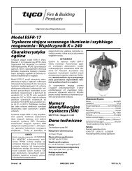
<strong>MODEL</strong> <strong>AV</strong>-1<br />
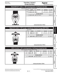
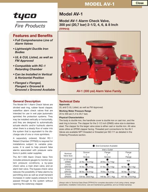
Model <strong>AV</strong>-1<br />
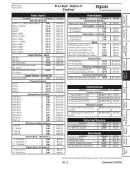
Model <strong>AV</strong>-1 Alarm Check Valve,<br />
300 psi (20,7 bar) 2-1/2, 4, 6, & 8 Inch<br />
(TFP910)<br />
Features and Benefits<br />
• Full Comprehensive Line of<br />
Alarm Valves<br />
• Lightweight Ductile Iron<br />
Bodies<br />
• UL & CUL Listed, as well as<br />
FM Approved<br />
• Compatible with RC-1<br />
Retarding Chamber<br />
• Can be Installed in Vertical<br />
& Horizontal Position<br />
• Flanged x Flanged,<br />
Flanged x Grooved &<br />
Grooved x Grooved Available<br />
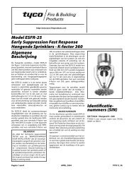
<strong>AV</strong>-1 (300 psi) Alarm Valve Family<br />
General Description<br />
The Model <strong>AV</strong>-1 Alarm Check Valves are<br />
divided seat ring, rubber faced clapper,<br />
waterflow alarm check valves that are<br />
intended for use in wet pipe (automatic<br />
sprinkler) fire protection systems. They<br />
may be installed vertically or horizontally,<br />
and they are designed to automatically<br />
actuate electric and/or hydraulic alarms<br />
when there is a steady flow of water into<br />
the system that is equivalent to the discharge<br />
rate of one or more sprinklers.<br />
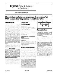
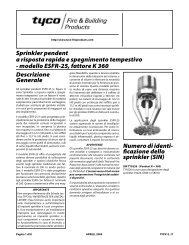
A separately ordered, Model RC-1<br />
Retard Chamber (TFP920) is required for<br />
installations subject to variable pressures.<br />
It is used to help prevent false<br />
alarms associated with pressure variations<br />
in public water supplies.<br />
The <strong>AV</strong>-1-300 Alarm Check Valve Trim<br />
includes pressure gauges to monitor system<br />
pressure conditions, a by-pass<br />
check valve, a main drain valve, and an<br />
alarm test valve. The bypass check valve<br />
reduces the possibility of false alarms by<br />
permitting slow as well as small transient<br />
increases in water supply pressure to be<br />
passed through to the system without<br />
opening the waterway clapper.<br />
Technical Data<br />
Approvals<br />
UL and C-UL Listed, as well as FM Approved.<br />
Working Water Pressure Range<br />
20 to 300 psi (1,4 to 20,7 bar).<br />
Physical Characteristics<br />
The body is ductile iron, the handhole cover is ductile iron or cast iron, and the<br />
seat ring is bronze. The clapper for the 2-1/2 inch (DN65) valve size is stainless<br />
steel. The clapper for the larger valve sizes is either cast or ductile iron. All valve<br />
sizes utilize an EPDM clapper facing. Threaded port connections for the <strong>AV</strong>-1<br />
Valves are available NPT threaded or threaded per ISO 7/1 as detailed in the<br />
Ordering Procedure section.<br />
Nominal<br />
Valve Size<br />
Groove<br />
x<br />
Groove<br />
End Connection Available<br />
Inlet x Outlet<br />
Flange<br />
x<br />
Groove<br />
Flange<br />
x<br />
Flange<br />
2-1/2 Inch<br />
(DN65) 22 lbs. (10,0 Kg) 28 lbs. (12,7 Kg)<br />
N/A<br />
4 Inch<br />
(DN100)<br />
6 Inch<br />
45 lbs. (20,4 Kg) 51 lbs. (23,1 Kg) 62 lbs. (28,1 Kg)<br />
(DN150) 68 lbs. (30,9 Kg) 78 lbs. (35,4 Kg) 93 lbs. (42,2 Kg)<br />
8 Inch<br />
(DN200) 129 lbs. (58,6 Kg) 148 lbs. (67,1 Kg) 167 lbs. (75,8 Kg)<br />
(Always refer to Technical Data Sheet [TFP910] for complete description of all Listing criteria, design<br />
parameters, installation instructions, care and maintenance guidelines, and our limited warranty).
<strong>MODEL</strong> <strong>AV</strong>-1<br />
Ordering Procedure<br />
Standard <strong>AV</strong>-1-300 Alarm Check Valve<br />
(American Standard Flange Drilling,<br />
American Threaded Ports, and American<br />
Groove Outside Diameter, as applicable):<br />
Specify: (specify size inch) Model <strong>AV</strong>-1-300<br />
Alarm Check Valve with (specify end connections),<br />
P/N (specify).<br />
2-1/2 Inch G x G<br />
2.88 inch (73,0 mm)<br />
Groove O.D. x 2.88<br />
inch (73,0 mm)<br />
Groove O.D. . . . . . . . .P/N 52-203-1-110<br />
2-1/2 Inch F x G<br />
ANSI Flange x<br />
2.88 inch (73,0 mm)<br />
Groove O.D. . . . . . . . .P/N 52-203-1-210<br />
4 Inch G x G<br />
4.50 inch (114,3 mm)<br />
Groove O.D. x 4.50<br />
inch (114,3 mm)<br />
Groove O.D. . . . . . . . .P/N 52-203-1-113<br />
4 Inch F x G<br />
ANSI Flange x<br />
4.50 inch (114,3 mm)<br />
Groove O.D. . . . . . . . .P/N 52-203-1-413<br />
4 Inch F x F<br />
ANSI Flange x<br />
ANSI Flange . . . . . . . .P/N 52-203-1-013<br />
6 Inch G x G<br />
6.62 inch (168,3 mm)<br />
Groove O.D. x 6.62<br />
inch (168,3 mm)<br />
Groove O.D . . . . . . . . .P/N 52-203-1-115<br />
6 Inch F x G<br />
ANSI Flange x<br />
6.62 inch (168,3 mm)<br />
Groove O.D . . . . . . . . .P/N 52-203-1-615<br />
6 Inch F x F<br />
ANSI Flange x<br />
ANSI Flange . . . . . . . .P/N 52-203-1-015<br />
8 Inch G x G<br />
8.62 inch (219,1 mm)<br />
Groove O.D x 8.62<br />
inch (219,1 mm)<br />
Groove O.D . . . . . . . . .P/N 52-203-1-916<br />
8 Inch F x G<br />
ANSI Flange x<br />
8.62 inch (219,1 mm)<br />
Groove O.D . . . . . . . . .P/N 52-203-1-816<br />
8 Inch F x F<br />
ANSI Flange x<br />
ANSI Flange . . . . . . . .P/N 52-203-1-016<br />
Standard Order <strong>AV</strong>-1-300 ValveTrim:<br />
Specify: Vertical, Closed Drain Galvanized<br />
Trim for (specify size)<br />
Model <strong>AV</strong>-1-300 Alarm Check Valve, P/N<br />
(specify).<br />
Vertical Closed Drain, Galvanized<br />
2-1/2 inch . . . . . . . . . . . . . .P/N 52-204-2-050<br />
4 or 6 inch . . . . . . . . . . . . . .P/N 52-204-2-951<br />
8 inch . . . . . . . . . . . . . . . . . .P/N 52-204-2-952<br />
1/2 INCH NPT<br />
CONNECTION<br />
FOR WATERFLOW<br />
PRESSURE ALARM<br />
SWITCH<br />
LOCATION<br />
FOR OPTIONAL<br />
ELECTRICALLY<br />
SUPERVISED<br />
N.O. ALARM<br />
CONTROL VALVE<br />
(BVS-3/4")<br />
<strong>MODEL</strong> RC-1<br />
RETARD<br />
CHAMBER<br />
ORDERED<br />
SEPARATELY<br />
(FOR VARIABLE<br />
PRESSURE<br />
SYSTEMS)<br />
RETARD<br />
CHAMBER<br />
RESTRICTION<br />
ASSEMBLY<br />
1/8"<br />
(3,2 mm)<br />
ORIFICE<br />
OUTLET<br />
WHEN FLOW THROUGH<br />
RESTRICTION ASSEMBLY<br />
INLET EXCEEDS OUTLET,<br />
RETARD CHAMBER<br />
BEGINS TO FILL<br />
WATERFLOW<br />
PRESSURE<br />
ALARM SWITCH<br />
Accessories<br />
Order the following accessories, as applicable:<br />
WATERFLOW<br />
TO WATER<br />
MOTOR ALARM<br />
7/32"<br />
(5,6 mm)<br />
ORIFICE<br />
INLET<br />
MAIN<br />
DRAIN<br />
VALVE<br />
Model RC-1<br />
Retard Chamber<br />
(required for variable pressure water supply<br />
conditions) . . . . . . . . .P/N 52-211-2-002<br />
Alarm Vent Trim<br />
(required when a water motor alarm is not<br />
installed) . . . . . . . . . . .P/N 52-201-2-012<br />
Model PS10-2A<br />
Potter Electric Waterflow Pressure Alarm<br />
Switch<br />
(required for electric signal indicating<br />
waterflow) . . . . . . . . .P/N 54-281-1-002<br />
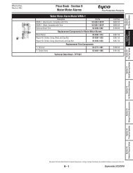
Model WMA-1<br />
Water Motor Alarm (required for a mechanical<br />
waterflow alarm) . .P/N 52-630-1-001<br />
<strong>Tyco</strong> is a registered trademark of <strong>Tyco</strong> and/or its affiliates in the United States and/or other countries.<br />
All other brand names, product names, or trademarks belong to their respective holders.<br />
3<br />
LOCATION<br />
FOR OPTIONAL<br />
ELECTRICALLY<br />
SUPERVISED<br />
N.O. ALARM<br />
CONTROL VALVE<br />
(BVS-1/2")<br />
RESTRICTION<br />
ASSEMBLY,<br />
3/4 INCH NPT<br />
CONNECTION FOR<br />
WATER MOTOR<br />
ALARM<br />
1/2 INCH NPT<br />
CONNECTION<br />
FOR WATERFLOW<br />
PRESSURE ALARM<br />
SWITCH<br />
4<br />
ONCE RETARD<br />
CHAMBER OVERFLOWS,<br />
WATERFLOW PRESSURE<br />
ALARM SWITCH AND<br />
WATER MOTOR<br />
ALARM ACTUATE<br />
3/4 INCH NPT<br />
CONNECTION FOR<br />
WATER MOTOR<br />
ALARM<br />
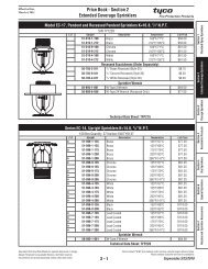
WATERFLOW<br />
TO SYSTEM<br />
2<br />
WATERFLOW<br />
THROUGH SEAT<br />
RING GROOVE AND<br />
ALARM PORT<br />
OPERATION<br />
1<br />
UPON SPRINKLER<br />
FLOW, WATERWAY<br />
CLAPPER OPENS<br />
ALARM<br />
TEST VALVE<br />
(NORMALLY<br />
CLOSED)<br />
MAIN<br />
DRAIN VALVE<br />
(NORMALLY<br />
CLOSED)<br />
2 INCH NPT<br />
CONNECTION<br />
T DRAIN<br />
SYSTEM<br />
PRESSURE<br />
GAUGE<br />
SUPPLY<br />
PRESSURE<br />
GAUGE<br />
<strong>MODEL</strong> <strong>AV</strong>-1<br />
ALARM VALVE,<br />
6 INCH (DN150)<br />
FLANGE x FLANGE<br />
SHOWN<br />
SYSTEM<br />
PRESSURE<br />
GAUGE<br />
SUPPLY<br />
PRESSURE<br />
GAUGE<br />
VERTICAL CLOSED DRAIN TRIM - STANDARD ORDER - SEMI-PREASSEMBLED<br />
<strong>Tyco</strong> <strong>Fire</strong> <strong>Products</strong><br />
Technical Services<br />
Ph: 800-381-9312<br />
Fax: 800-791-5500<br />
www.<strong>Tyco</strong>-<strong>Fire</strong>.com<br />
<strong>Tyco</strong> <strong>Fire</strong> <strong>Products</strong> reserves the right to change product design and specifications 2<br />
without notice. Copyright © 2004 <strong>Tyco</strong> <strong>Fire</strong> <strong>Products</strong> LP. All rights reserved.<br />
Printed in USA /TFP-<strong>AV</strong>1/4M/CPI/09-04