MOSFET N-channel depletion switching transistor
MOSFET N-channel depletion switching transistor
MOSFET N-channel depletion switching transistor

Create successful ePaper yourself
Turn your PDF publications into a flip-book with our unique Google optimized e-Paper software.
DISCRETE SEMICONDUCTORS<br />
DATA SHEET<br />
BSD22<br />
<strong>MOSFET</strong> N-<strong>channel</strong> <strong>depletion</strong><br />
<strong>switching</strong> <strong>transistor</strong><br />
Product specification<br />
File under Discrete Semiconductors, SC07<br />
December 1997
Philips Semiconductors<br />
Product specification<br />
<strong>MOSFET</strong> N-<strong>channel</strong> <strong>depletion</strong> <strong>switching</strong> <strong>transistor</strong><br />
BSD22<br />
DESCRIPTION<br />
Marking code: M32<br />
Symmetrical insulated-gate silicon<br />
MOS field-effect <strong>transistor</strong> of the<br />
n-<strong>channel</strong> <strong>depletion</strong> mode type.The<br />
<strong>transistor</strong> is sealed in a SOT143<br />
envelope and features a low<br />
ON-resistance and low<br />
capacitances.The <strong>transistor</strong> is<br />
protected against excessive input<br />
voltages by integrated back-to-back<br />
diodes between gate and substrate.<br />
Applications:<br />
• analog and/or digital switch<br />
handbook, halfpage<br />
4<br />
1<br />
3<br />
2<br />
g<br />
d<br />
b<br />
s<br />
• switch driver<br />
Top view<br />
MAM389<br />
• convertor<br />
• chopper<br />
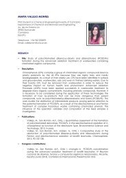
PINNING<br />
1 = substrate (b)<br />
2 = source<br />
3 = drain<br />
4 = gate<br />
Fig.1 Simplified outline and symbol.<br />
Note<br />
1. Drain and source are<br />
interchangeable<br />
QUICK REFERENCE DATA<br />
Drain-source voltage V DS max. 20 V<br />
Gate-source voltage V GS max.<br />
+ 15 V<br />
− 40 V<br />
Drain current (DC) I D max. 50 mA<br />
Total power dissipation up to T amb =25°C P tot max. 230 mW<br />
Junction temperature T j max. 125 °C<br />
Drain-source ON-resistance<br />
V GS = 10 V; V SB = 0; I D = 1 mA R DSon max. 30 Ω<br />
Feed-back capacitance<br />
V GS =V BS = −5 V; V DS = 10 V; f = 1 MHz C rss typ. 0.6 pF<br />
December 1997 2
Philips Semiconductors<br />
Product specification<br />
<strong>MOSFET</strong> N-<strong>channel</strong> <strong>depletion</strong> <strong>switching</strong> <strong>transistor</strong><br />
BSD22<br />
RATINGS<br />
Limiting values in accordance with the Absolute Maximum System (IEC 134)<br />
Drain-source voltage V DS max. 20 V<br />
Source-drain voltage V SD max. 20 V<br />
Drain-substrate voltage V DB max. 25 V<br />
Source-substrate voltage V SB max. 25 V<br />
Gate-substrate voltage V GB max. ± 15 V<br />
Gate-source voltage V GS max.<br />
+ 15 V<br />
− 40 V<br />
Drain current (DC) I D max. 50 mA<br />
Total power dissipation up to T amb =25°C (1) P tot max. 230 mW<br />
Storage temperature range T stg −65 to + 150 °C<br />
Junction temperature T j max. 125 °C<br />
THERMAL RESISTANCE<br />
From junction to ambient in free air (1) R th j-a = 430 K/W<br />
Note<br />
1. Device mounted on a ceramic subtrate of 8 mm × 10 mm × 0.7 mm.<br />
CHARACTERISTICS<br />
T amb =25°C unless otherwise specified<br />
Drain-source breakdown voltage<br />
V GS =V BS = −5 V; I S = 10 nA V (BR)DSX min. 20 V<br />
Source-drain breakdown voltage<br />
V GD =V BD = −5 V; I D = 10 nA V (BR)SDX min. 20 V<br />
Drain-substrate breakdown voltage<br />
V GB = 0; I D = 10 nA; open source V (BR)DBO min. 25 V<br />
Source-substrate breakdown voltage<br />
V GB = 0; I S = 10 nA; open drain V (BR)SBO min. 25 V<br />
Drain-source leakage current<br />
V GS =V BS = −5 V; V DS = 10 V I DSoff typ. 1.0 nA<br />
Source-drain leakage current<br />
V GD =V BD = 5 V; V SD = 10 V I SDoff typ. 1.0 nA<br />
Gate-substrate leakage current<br />
V DB =V SB = 0; V GB = ± 15 V I GBS max. 10 nA<br />
Forward transconductance at f = 1 kHz<br />
V DS = 10 V; V SB = 0; I D = 20 mA<br />
min. 10 mS<br />
g fs<br />
typ. 15 mS<br />
Gate-source cut-off voltage<br />
V DS = 10 V; V SB =0;<br />
I D =10µA −V (P)GS max. 2.0 V<br />
December 1997 3
Philips Semiconductors<br />
Product specification<br />
<strong>MOSFET</strong> N-<strong>channel</strong> <strong>depletion</strong> <strong>switching</strong> <strong>transistor</strong><br />
BSD22<br />
Drain-source ON-resistance<br />
I D = 1 mA; V SB =0;<br />
typ.<br />
max.<br />
25<br />
50<br />
Ω<br />
Ω<br />
V GS =5 V R DSon<br />
typ.<br />
V GS = 10 V<br />
R DSon<br />
max.<br />
15<br />
30<br />
Ω<br />
Ω<br />
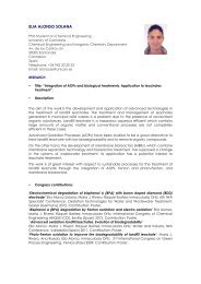
Capacitances at f = 1 MHz<br />
V GS =V BS = −5 V; V DS = 10 V<br />
Feed-back capacitance C rss typ. 0.6 pF<br />
Input capacitance C iss typ. 1.5 pF<br />
Output capacitance C oss typ. 1.0 pF<br />
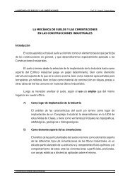
Switching times (see Fig.3)<br />
V DD = 10 V; V i = −5 V to + 5 V t on typ. 1.0 ns<br />
t off typ. 5.0 ns<br />
handbook, halfpage<br />
C iss = C gs + C gd + C gb<br />
C oss = C gd + C bd<br />
g<br />
C gd<br />
C gb<br />
C gs<br />
d<br />
C bd<br />
b<br />
C bs<br />
s<br />
MBK301<br />
Fig.2 Capacitances model.<br />
age<br />
V DD<br />
handbook, full pagewidth<br />
50 Ω 0.1 µF<br />
V o<br />
630 Ω<br />
INPUT<br />
10%<br />
90%<br />
90%<br />
10%<br />
t r<br />
t f<br />
V i<br />
50 Ω<br />
T.U.T<br />
OUTPUT<br />
90%<br />
t on<br />
t off<br />
90%<br />
MBK300<br />
10%<br />
10%<br />
MBK296<br />
Fig.3 Switching times and input and output waveforms; R i =50Ω; t r < 0.5 ns; t f < 1.0 ns; t p = 20 ns; δ < 0.01.<br />
December 1997 4
Philips Semiconductors<br />
Product specification<br />
<strong>MOSFET</strong> N-<strong>channel</strong> <strong>depletion</strong> <strong>switching</strong> <strong>transistor</strong><br />
BSD22<br />
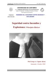
PACKAGE OUTLINE<br />
Plastic surface mounted package; 4 leads<br />
SOT143B<br />
D<br />
B<br />
E<br />
A<br />
X<br />
y<br />
v M<br />
A<br />
H E<br />
e<br />
b p<br />
w M<br />
B<br />
4<br />
3<br />
Q<br />
A<br />
A1<br />
1<br />
2<br />
c<br />
b 1<br />
Lp<br />
e1<br />
detail X<br />
0 1 2 mm<br />
scale<br />
DIMENSIONS (mm are the original dimensions)<br />
UNIT<br />
mm<br />
A<br />
1.1<br />
0.9<br />
A 1<br />
max<br />
0.1<br />
b p<br />
0.48<br />
0.38<br />
b 1<br />
0.88<br />
0.78<br />
c<br />
0.15<br />
0.09<br />
D<br />
3.0<br />
2.8<br />
E<br />
1.4<br />
1.2<br />
e<br />
1.9<br />
e 1<br />
1.7<br />
H E<br />
2.5<br />
2.1<br />
L p Q v w y<br />
0.45 0.55<br />
0.15 0.45<br />
0.2 0.1 0.1<br />
OUTLINE<br />
VERSION<br />
REFERENCES<br />
IEC JEDEC EIAJ<br />
EUROPEAN<br />
PROJECTION<br />
ISSUE DATE<br />
SOT143B 97-02-28<br />
December 1997 5
Philips Semiconductors<br />
Product specification<br />
<strong>MOSFET</strong> N-<strong>channel</strong> <strong>depletion</strong> <strong>switching</strong> <strong>transistor</strong><br />
BSD22<br />
DEFINITIONS<br />
Data sheet status<br />
Objective specification This data sheet contains target or goal specifications for product development.<br />
Preliminary specification This data sheet contains preliminary data; supplementary data may be published later.<br />
Product specification This data sheet contains final product specifications.<br />
Short-form specification The data in this specification is extracted from a full data sheet with the same type<br />
number and title. For detailed information see the relevant data sheet or data handbook.<br />
Limiting values<br />
Limiting values given are in accordance with the Absolute Maximum Rating System (IEC 134). Stress above one or<br />
more of the limiting values may cause permanent damage to the device. These are stress ratings only and operation<br />
of the device at these or at any other conditions above those given in the Characteristics sections of the specification<br />
is not implied. Exposure to limiting values for extended periods may affect device reliability.<br />
Application information<br />
Where application information is given, it is advisory and does not form part of the specification.<br />
LIFE SUPPORT APPLICATIONS<br />
These products are not designed for use in life support appliances, devices, or systems where malfunction of these<br />
products can reasonably be expected to result in personal injury. Philips customers using or selling these products for<br />
use in such applications do so at their own risk and agree to fully indemnify Philips for any damages resulting from such<br />
improper use or sale.<br />
December 1997 6