Frameless Kit Motors - Grp6.com
Frameless Kit Motors - Grp6.com
Frameless Kit Motors - Grp6.com

Create successful ePaper yourself
Turn your PDF publications into a flip-book with our unique Google optimized e-Paper software.
Rotor Assembly:<br />
Assemble rotor to shaft with a locational clearance fit of 0.013mm (0.0005in) to<br />
0.038mm (0.0015in) diametrical clearance.<br />
Shoulder / Adhesive Method:<br />
Fabricate shaft with shoulder. Secure rotor assembly and sleeve with adhesive.<br />
Loctite#609 or equivalent.<br />
Spring Pin / Retaining Ring Method:<br />
Fabricate a sleeve (steel or aluminum) with anti rotation spring pin groove.<br />
Fabricate shaft to accept retaining ring and spring pin. Permanently bond to<br />
rotor assembly.<br />
Final Assembly:<br />
Rotor magnets to be in line with stator laminations and concentric to stator<br />
lamination I.D. within 0.127mm (0.005in) MAX.<br />
Caution:<br />
Rotor assembly magnets are powerful and fragile!<br />
Do not place near magnetically sensitive material<br />
Do not place near other ferromagnetic materials such as iron, steel and nickel<br />
alloys. Strong uncontrolled attraction may damage magnets on contact.<br />
When assembling the rotor into the stator, high radial forces will be experienced,<br />
which can cause the magnets to "crash" into the stator and be damaged and / or<br />
cause bodily injury!<br />
The following precautions should be taken:<br />
Wrap the rotor with a thin (0.005in thick) Mylar sleeve which will fill the air<br />
gap between the rotor and stator during assembly and can be easily removed<br />
when assembly is complete.<br />
Support the rotor and stator assemblies in a fixturing arrangement which will<br />
prevent radial motion while the two assemblies are being mated.<br />
Example:<br />
1. Hold the rotor / shaft / product assembly in a machine tool vise on the base of<br />
an arbor press.<br />
2. Fasten the stator assembly to the vertical moving member of the arbor press,<br />
away from the stator.<br />
3. Slowly lower the stator assembly around the rotor / shaft / product assembly.<br />
4. Tighten all fasteners to complete assembly.<br />
5. Remove Mylar shim and check for rotational clearance.<br />
Improper assembly of rotor into stator can cause serious injury and or damage to<br />
equipment.<br />
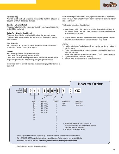
How to Order<br />
Order<br />
Numbering<br />
Example:<br />
K 0 4 4 1 0 0 – E Y 2 XXX<br />
MODEL<br />
032<br />
044<br />
064<br />
089<br />
375<br />
127<br />
500<br />
178<br />
700<br />
254<br />
STACK LENGTH<br />
025 (0.25”)<br />
050 (0.50”)<br />
075 (0.75”)<br />
100 (1.00”)<br />
150 (1.50”)<br />
200 (2.00”)<br />
WINDING (1)<br />
1<br />
2<br />
3<br />
4<br />
5<br />
6<br />
7<br />
8<br />
9<br />
E<br />
F<br />
G<br />
H<br />
J<br />
K<br />
L<br />
CONNECTION (2)<br />
Y=Wye<br />
D=Delta<br />
COMMUTATION<br />
1 = Without<br />
2 = With Integral<br />
(1) Consult Parker Bayside (1-800-305-4555 or<br />
www.baysidemotion.com or www.parkermotion.com)<br />
for specific winding designations.<br />
(2) Consult factory for special options<br />
Parker Bayside <strong>Kit</strong> <strong>Motors</strong> are supported by a worldwide network of offices and local distributors.<br />
Call 1-800-305-4555 for application engineering assistance or for the name of your local distributor.<br />
Information can also be obtained at www.baysidemotion.com or www.parkermotion.com.<br />
Specifications are subject to change without notice.<br />
155