You also want an ePaper? Increase the reach of your titles
YUMPU automatically turns print PDFs into web optimized ePapers that Google loves.
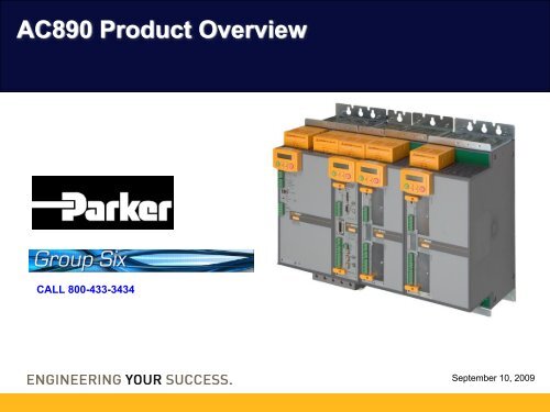
<strong>AC890</strong> <strong>Product</strong> <strong>Overview</strong>CALL 800-433-3434September 10, 2009
Control and Option BoardsONE main control boardA wide variety of optional plug-in feedback,communications and I/O expansion boardspiggyback onto the Control Board.DIRECT PROCESSING COMMS• HIGH SPEED• LOW COST• Expansion I/O card• Follower board(encoder and resolver types)3CONTROL BOARD• V/Hz,SV,Vector• Servo control• On-board I/OFEEDBACK CARDTYPES• Resolver card• Encoder card types:• enDat (sin/cos)•incremental encoderFirewire• DeviceNet• Profibus DP• ControlNet• Firewire• Ethernet IP/TCP• Can Open• ProfiNetEtherCATIEEE1394Firewire comms!ProfibusFIELDBUSCOMMSFirewire
ProgrammingPort USBAll Control ConnectionsSpeedPotentiometerSpeed FdbkTorque FdbkEncoder24V AuxSupplyOptionalHealthSHLD-+Z/ZB/B24V0V24VA/A0V0VAnalog I/P 1Analog I/P 2Speed Trim+10V-10V4 analog inputs2 analog outputsSpeedFeedback(encoder optionshown)daisy-chainablepwr supply input24V0V• PC programming port• Quick disconnect terminal block• Analog outputs for torque and speed• Dry contact output for ‘health’ status (rated 24vdc 1amp resistive)• Daisy-chain power supply input for off-line use• 4 analog inputs• 5 digital inputs• 2 programmable digital I/O• 24 Vdc control logic• Outputs for ‘run’ status and ‘zero speed’4JogStartStopReverseTorqueSpareSpareRunningZero Speed+DR+ZS6 digital inputs2 digital I/O
Auxiliary PowerThe <strong>AC890</strong> allows you toconfigure the drive using thekeypad or pc without applyingmain powerpc configurationAux24Vsupply+24v+24v0v0vYou can safely check theoperation of the whole systemby supplying just the 24V DCControl power!(An external 24VDC Control Supplywill power the unit for configurationpurposes. It is not required when the3-phase supply is present)
I/O Terminal Interface Module – NEW RELEASE 9/09!For <strong>AC890</strong> units used in panels or systems, this option will make wiringeasier and more organized• Faster panel wiring and assembly time• Ties stop logic from multiple drives together• Eliminates intermittent connections from loose screw terminals• Provides additional circuit common connections• Cage clamp spring pressure terminals• Accepts wire size AWG12 - 28• Pitch spacing: 5mm• Keyed cables for foolproof connections• Includes module to module jumper for multi-driveapplications6
Available in 2 StylesStyle 1: STAND ALONE “SD”B C DA complete AC input-to-AC motoroutput controller complete withpower input and output terminals,and access to all feedback andnetworking options1 - 10 HP.75 – 7.5 KW15 - 20 HP11 - 15 KW25 - 40 HP18 - 30 KWAC POWERINPUTAC INDCAC OUTStand Alone Drives come complete with abuilt-in Dynamic Brake switch withprovisions to add an external resistor.MOTOR
Basic SSD Drives AC Power CircuitBRAKEOPTION3 PHASEMAINS50/60 HzSMPSMOTOR0-415V0-480HzCONTROLTERMINALSMICROPROCESSORCONTROLLERHIGHFREQUENCYPWM11
AC Drives and Power FactorAC INPUT P.F. = .96Motor P.F. = .70(Light Load)ACInputREACTIVEFLOWM12AC Drives inherently correct motor Power Factor• Reactive current bi-directionally flows between the inductive motor and bus capacitors.• Input PF has no relationship to motor PF.• Since input current is in-phase with voltage, input displacement PF is always near unity.Never use power factor correction capacitors with AC Drives!!!
Power Factor on AC and DC Drives.96.85ACOn AC Drives, input displacementpower factor remains nearlyconstant with speed & load.POWERFACTOR.30DCOn DC Drives, power factor variesdirectly with SCR phase-firingangle, peaking near .85 .Since power increases linearlywith speed, the effects of lowpower factor at low speed arenegligible.20%SPEED100%13
Torque vs. Speed Curve225Motor base speed: 1750 RPM (4-pole)60 Hzcurve%T17515010050Base120 HzcurvePeak Inverter Torque(150 -200% current)100% currentoperating lineSpeed1800 3600Slip (50 rpm)Slip (50 rpm)• Above base speed, continuous torque declines to 50% at 2 x base.• Peak Inverter (overload) torque declines even more rapidly.14• Motor slip increases, for a given torque level.
Basic V/HZ Control Circuit:Input, Feedback and Control SignalsVOperatorInterfaceSpeed referenceDC Bus current &voltage feedbackIGBT FiringSignalsPWMmicroprocessorcontrollerMotor current &voltagefeedbackf15
How Slip Compensation improvesspeed regulationExample: Motor under load at 30 HzBEFORE%T17515010030 Hz curveFull load 30 Hzoperating point (100%current & torque)850 RPMSync. or “no-load”30 Hz speed900 RPM%T175150100AFTERNew 31.7 Hzcurve900 RPM950 RPMSpeedSlip (50 rpm)SpeedSlip (50 rpm)A motor will lose 50 rpm underfull load with 30 Hz appliedfrequency, slipping from 900 to850 RPM.By sensing current and othervariables, SLIP COMP will apply31.7 Hz to the motor, restoringthe speed to 900 RPM.16
17Autotuning on Sensorless Vector DrivesFACT: Most motor electrical parameters aredifficult to obtain from the manufacturer.ROTOR RESISTANCEROTOR REACTANCEMAGNETIZING CURRENTSTATOR RESISTANCELEAKAGE REACTANCE?????Not typically found on motor nameplateA Sensorless Vector AUTOTUNE function makes the job easy:1. Enter nameplate motor parameters (base speed, full load amps, voltage,frequency, power factor).2. Run the ‘AUTOTUNE ‘ function. The controller will pulse the motor &determine approximate motor electrical characteristics for SENSORLESSVECTOR Operation.3. The S-V algorithm can now compute torque- and magnetizing currentvectors for more precise motor control.
Flux Vector Control ElementsInput, Feedback and Control SignalsEncoder FeedbackSpeed and / orTorque referenceManmachineInterfaceDC Bus voltagefeedbackSEQFWRDEVLOCALIGBT GatingSignalsPWMmicroprocessorcontroller withVector algorithmMotor current &voltage feedback18
AC VECTOR CONTROL LOOPSAC Vector DriveSpeed LoopTorque LoopEncoderSpeed ReferenceTorque ReferenceSpeed ErrorSpeedRegulatorTorque Ref.Actual TorqueTorqueRegulatorFreq. & VoltageReferencePWMFiringTorqueCalculatorFrequency FeedbackSpeed Feedback19
Motor Current VectorsMagnetizingCurrentTotal Current is the Vector sum ofMagnetizing and Torque-producingcurrent, which are at a right angleto each other.Torque-Producing CurrentStatorResistanceStatorLeakageReactanceAirGapRotorRotorReactanceTorqueCurrentR 1X LRX MX RR LOADTotal CurrentMagnetizingCurrent20
Motor Current VectorsMagnetizingCurrentMagnetizingCurrentTorque-ProducingCurrentLIGHTLOADTorque-Producing Current• High % of total current is “magnetizing” current• Magnetizing current is reactive (low p.f.)• Measured (total) motor current is not a goodindicator of load level.MEDIUMLOAD&HEAVYLOAD• Most of total current istorque-producing• Motors run at highpower factor• Total motor current isproportional to load level.MagnetizingCurrentTorque-Producing Current21
4-Quadrant Operation of AC Motors onInverter PowerClockwiseTORQUEREVERSEREGENERATINGFORWARDMOTORING-RPM+ RPMREVERSEMOTORINGFORWARDREGENERATINGCounter-ClockwiseTORQUE22
Conditions for Regenerating onan AC MotorAC Motors regenerate when pulled faster than theirsync speed at the applied frequency.At 60 Hz, if a motor is pulled faster than 1800 RPM*,the motor will behave as an induction generator.Regeneration conditions:• Overhauling loads• Fast deceleration of high inertial loads• Stopping on a timed-ramp• Cyclic loads or eccentric shaft loadingREVERSEREGENERATINGFORWARDMOTORINGROTATIONPULL* 1750 RPM basespeed at 60 Hz-RPM+ RPMREVERSEMOTORINGFORWARDREGENERATING23WEIGHT
AC Drive RegenerationEnergy Flow:ONE - WAYTWO - WAYACInputDCBusCaps+_IGBTsM• Current flows back into the DC bus, via the IGBT switching & back diodes.• AC Drive front-end rectifier is unidirectional; energy cannot flow back into the ACline.• Some returned energy is dissipated in losses in the capacitors, switches, andmotor windings (10-15%).• Excessive regeneration can cause problems, such as DC Bus Overvoltage.24
Dynamic Braking on AC DrivesACInputDCBusCaps+_V DC FeedbackDBRMDB is ACTIVE when:• Motor has an overhauling load• Fast decel of high-inertial load• Stopping in ramp-to-rest modeSIGNALDYNAMICBRAKINGCONTROLDB is NOT ACTIVE when:• Decelerating a frictional load• Stopping in coast-to-rest mode• Drive has Overvoltage or abrake resistor/switch fault or ifpower is removed25DYNAMIC BRAKING is typically an option for AC DrivesA seventh IGBT, integrally mounted, is modulated when DC Bus voltage isexcessive.Resistor Grids (external on ratings 5 HP & above) dissipate the excess energy.DB is duty-cycle limited to a set number of stopping operations
Dynamic Braking on AC Drives:Application ConsiderationsDB is not failsafe: If power is removed, DB will not function.DB is available whenever power is applied: The DB is availableprovided the drive is not faulted with Overvoltage or BrakeResistor/Switch.DB is suitable for intermittent operation only: 4 stops at 100% load perhour permitted or continuous braking at 30% load. Other regenerativesolutions exist for long-term overhauling loads.26
Line Regenerative AC DrivesBI-DIRECTIONAL POWER FLOWLINEV DC FeedbackMLOADIGBT FiringSignalsIGBT FiringSignalsCONVERTERPWMmicroprocessorcontrollerINVERTER27• Two sets of 6 - IGBT bridges• Gating control for both sets• Converter IGBTs modulate on when bus voltage is excessive.• More complex regulator design• More conducted noise to power line
Available in 2 StylesStyle 2: COMMON BUSSupply Section “CS”Drive Section “CD”B C DCommon Bus Drives (CD) areindividual motor output sections thateasily connect to a Common BusSupply (CS) with a unique, easy-toinstallDC busbar system• Integral fusing provides branchprotection• No power interlocks or inputreactors requiredup to 45 HPup to 30 KW50 - 135 HP37 - 90 KW1 - 10 HP.75 – 7.5 KW15 - 20 HP11 - 15 KW25 - 40 HP18 - 30 KW• Each CD provides access to allfeedback and networking optionsDC BUSDC OUTDC INCDDC INCDAC INCSAC OUT AC OUTAC OUTAC POWER INPUTexample of Common Bus setupSimple common busconnection for quick andeasy installation• Bookshelf frames shown.higher ratings available through 1600HP
Common Bus Drive Power Connections:Common DriveDC+Internal FusingIGBTsUVWMDC-External DCfusing requiredon frames E & FUVWGround29
Space and Cost SavingsCONVENTIONALDRIVE SYSTEMCircuit BreakersFusingComponent<strong>AC890</strong> MODULARDRIVE SYSTEMLine ReactorsContactorsReductionEnclosure SizeEngineeringWiringOther ComponentsSwitchgear50% SpaceReduction10-Drive SystemFewer lossesEfficient commonbusconnectionImprovedEfficiency
Input Power ConfigurationsParallel Input Modules and multi-pulse configurations*6 pulse 12 pulse 18 pulseCS CS CS CS CS CS CSAFECDEnergy savingLineRegenerativeActive FrontEnd (AFE)types are alsoavailable30 o shift20 o shift 20 o shiftphase-shifttransformer*(user supplied)LCL Filter10% de-rate2 x 60kW x .9 =108kW* supply windingsmust be isolatedReduced harmonicsMinimal harmonicsNegligible harmonics
Common Bus Supply Power Connections:Common Supply(internal)DC+L1L2L3DB ResistorThermal ProtectionDB ResistorDC-Ground3 phase PowerCircuit Breaker3% Line Reactor500Vac SCRFusesThis Silicone Cord is to protectSomeone from touching the DC+ andDC- Terminals. Remove Only if usingTerminals.32
Typical System:135HP Common Bus350 H x 1000 W x 260 D (mm)14” H x 39” W x 14” D135HP100kW10HP7kW30HP22kW25HP18kW20HP15kW5HP4kW5HP4kW40HP30kWCSMODULE3 phase Power
Common Bus Adapter Module2 TypesRated for 80A DC• Provides easy wire connections to the Common DC Buswithoutcapacitance• Built-in surge protection fusing• 2 types: with or without added capacitance• Capacitance type adds greater line dip ride-throughwithcapacitance• Provides connections for adding <strong>AC890</strong> row sections• Same bus-bar connections as other <strong>AC890</strong> modules
Common Bus Adapter Module ConnectionsEach bus bar ratingis 140A maxAC LINEPOWERINPUTCOMMONBUSINPUTMODULE45kW75HPtotalLine#1Common Bus AdapterModules have DC Busterminals that provideconnection toadditional sectionsBridge Moduleconnection toadditional sectionsOutput Drives30kW40HPtotalLine#2COMMON BUSADAPTER MODULEOutput Drives
890 AFE – Active Front End:5HP 20HP (@460V)Standard CD Drives withSpecial Input ConnectionAny CD drive can be configuredto run as an AFE• Connects to output via busbar connections ontop of module• Connect LCL Filter and External Pre-chargecircuit big enough for all Drives.• Adds regenerative capability, so no DBresistors are needed.• Has almost unity power factor and veryminimal harmonics.36
AFE Power Connections:Common Drive(Setup for AFE)IGBTsDC+3 phase PowerUVWDC-LCL FilterCircuit BreakerFusePre-ChargeResistorUVWGround3 phase Power3%Line Reactor5%Line ReactorPre-ChargeRelayThe Pre-Charge circuit has to be sized largeEnough for all the drives the AFE is supplying.37
Energy Saving Line Regenerative SolutionsACTIVE FRONT ENDprovides CLEAN POWERCommon Bus Drive sections can alsobe configured as ACTIVE-FRONT-END INPUT SECTIONS, providingtrue line-regenerative 4-quadrantcontrol with no harmonicsAFEActive-Front-EndTypical 40HP Line Regenerative SystemCOMMONBUSINPUTMODULERequires:• External pre-charge• External reactorProvides:• Full bi-directional power flow• 150%, 60sec overload• Sinusoidal input current• Fully Line Regenerative• Low Power Line Harmonics• UNITY POWER FACTORBi-directionalPower FlowLCL Filter
Line Regenerative SolutionsLarger <strong>AC890</strong> systemscan be matched with separate higherpowerActive Front End units. Multiplerows of <strong>AC890</strong> Common Bus Drives arebridged together using Common BusAdapter modules.COMMON BUSADAPTERTypical 75kW (100HP)Line Regenerative SystemAFEActive-Front-EndHIGH AMP BUSBAROutput Drives37kW50HPtotal#175kW100HPCOMMON BUSADAPTERBi-directionalPower Flow37kW50HPtotal#2Output DrivesLCL FilterActive-Front-End power ratings available through 1200KW (1600HP)
ProgrammingPort USBAFE Control Connections• PC programming port (mini USB)• Dry contact output for Pre-Charge Relay• Daisy-chain power supply input for off-line use• Digital Input to verify closure of Pre-charge relay• 24 Vdc control logic24V AuxSupplyOptional24V0Vdaisy-chainablepwr supply input24V0V• outputs for ‘run’ status and ‘Health’Pre-ChargeRelay24V0VPre-ChargeClosed6 digital inputs40RunningHealth+RR+HR2 digital I/O
Easy set-up using DSEconfiguration tool• DSE (Drive System Explorer) hasa full Help system• Insert the DSE disk into your PC /follow the on-screen instructionsMini USB port41Connecting to a PCOutput Modules and Drive Modules connect to your PC usinga mini-USB connector for loading your application details
Fast-and-easyproject creation andonline monitoring toolSet upparameters &Create ProjectsDrag-anddropapplicationblocksChartvariableson-lineMonitoringand on-linetuning42
Performance Levels<strong>AC890</strong> can deliver the right level of performance to precisely matchyour application needs. By offering different performance levelpackages, your <strong>AC890</strong> system has the flexibility to meet all of yourdemands.LEVEL12ADVANCED PERFORMANCEStandard Features, plus: Motion control firmware with added position loop,motion control function blocks, move incremental, move absolute, move home,line drive master ramp and section control, winder blocks (SPW, CPW), fullfunction PID, state machine, and others.HIGH PERFORMANCEAll Advanced Performance features, plus: Library of pre-engineered applicationspecific LINK VM function blocks such as: Shaftless Printing, precision camming,cut-to-length, precision winding, traversing and others.43
Duct Kit for B-D Frame 890s• Modular design for easyinstallation• Ducts air from powerheatsink assemblies• Reduces overallenclosure size needed• Control electronicsremain in clean airenvironment
Duct Assembly Option - ExampleSizingSoftwareAvailable!<strong>AC890</strong> DUCTING OPTIONCOMMON DRIVE (CD)COMMON DRIVE (CD)COMMON DRIVE (CD)COMMON DRIVE (CD)COMMON DRIVE (CD)COMMON DRIVE (CD)COMMON DRIVE (CD)COMMON DRIVE (CD)COMMON DRIVE (CD)COMMON DRIVE (CD)COMMONBUSSUPPLY(CS)Liner Takeup, Pull Rolls, Conveyors & Core Takeup Drives
Ducting OptionsDynamic BrakingResistors<strong>AC890</strong> Systems provide the ability toforce air to cool each row of drives, andduct exhaust air through the enclosuretop.DC CommonBus Supply162AUpper drive row ductingOutput Drive Sections(5) x 20HPThis ingenious configuration alsoprovides cooling to the dynamic brakingresistor gridsLower drive row ductingDC CommonBus Supply162AOutput Drive Sections(2) x 40HP(2) x 10HPDuct kits for size B-D areshown…also available for largerframe sizes.
6901 Keypad OptionThe 6901 keypad (also used on theDC590+ and AC690+ series products) canbe used to program the <strong>AC890</strong>• Plain language programming• Upload/store/download• Diagnostics
Option CardsSpeed feedbackSpeed FeedbackTech card A• Available options:• Sin-cos encoder• Incremental encoder• ResolverTech card BControl board49
Speed Feedback OptionsFeedback Type Used on Fitted to Slot ConnectorIncrementalEncoder8902/EQInduction motorAll versionsSlot FPluggablePhoenixScrew terminalResolverPMAC servoSlot FD-sub8902/REAll versions25 pinSin-Cos EncoderInduction motorSlot FD-sub8902/M1PMAC servo25 pinAbsolute ENDATv2.1 Encoder8902/M1Induction motorPMAC servoSlot FD-sub25 pinReference pulseEncoderLine reference ormark inputSlot APluggablePhoenix8903/EQScrew terminalReferenceSin-Cos EncoderLine reference ormark inputSlot AD-sub25 pin8903/M1
Incremental (Pulse) EncoderEncoder Compatibility• Supply output– Adjustable between 10v and 20v– 3W available– Indefinite short circuit protection– Isolated from drive and encoder inputs51• Encoder Inputs– Differential inputs ±4v to ±30v. (NOT RS422or RS485)– Input current < 10mA– Input pairs are isolated from drive and fromeach other– Single-ended inputs• Low = 0 to 5v: High = 10v to 30v
Incremental (Pulse) EncoderPerformance• Maximum Input Frequency:– Differential inputs 250kHz– Single-ended inputs 200kHz• Digital filtering provides excellent noiseimmunity, easily exceeding EN61000requirement• Differential input current is nowsymmetrical about 0mA52
Incremental (Pulse) EncoderMark Input• Used for registration applications• Polarity selection:– Leading edge (default)– Trailing edge– Rising edge– Falling edge53Fault Detection• Fault conditions are detected and reported to thehost drive:– Lost connection in differential mode– Mis-wiring in differential mode– Invalid quadrature sequence
Sin / Cos Encoder Option• Sampling the 1 V p-pquadrature differentialsignals of a 1024 lineencoder using 12 bitADCs gives a resolutionof over 4 million countsper revSin/Cosencoder input• This equates to aresolution of 0.31 arcseconds or on a print rollof 1m diameter, thiscorresponds to 785nmFeedbackencoder54
Other Features•Encoders available use either a 5V supply or 7-12V. The card supplies 5V and 10V.•Firmware supports Heidenhain EnDat v2.1absolute position data for single turn and multiturn encoders.•Maximum input quadrature frequency is 200kHz1024line - 12000rpm2048line - 6000rpmNote: not all encoder are rated up to these speeds.55
Option CardsSin/Cos Encoders• Incremental• Collimated light is passed through a scanning reticle• As the graduated disk spins the light is modulated.• If the gaps in the gratings are aligned light passesthrough.• If the gaps are not aligned no light passes through.• Photocells convert these variations in light intensity intosinusoidal signals, typically 2048 per rev.• The 890 processes these sin/cossignals by passing them througha 12 bit A-D Converter. This gives8,388,608 counts per revolution.56
Option CardsSin/Cos Encoders• Absolute Single Turn• Contains the sin/cos incrementalchannels.• Has an extra serial channel for Absolute positioninformation.(Endat 2.1) so that the shaft position is known on power up.• Used when position information is required but no gearboxis fitted.57
Option CardsSin/Cos Encoders• Absolute Multi Turn• This is the same as single turn but also remembers up to4096 turns of the shaft.• Used when a gearbox is connected between the motor andthe load.• Note: Has to be an integer gear ratio (e.g. 4:1). To be changedin future releases.• Suitable Heidenhain Range• Incremental – ERN420• Absolute Single Turn – ECN413• Absolute Multi Turn – EQN42558
ELECTRONIC LINE SHAFTING FEATURE*MASTERFOLLOWERMASTER LINEREFERENCEENCODERREFERENCEINPUTPHASE-LOCKEDLOOP* with systemboard option• Absolute positionregulation betweenmotors• Closed-loop vectormode operation59ALSO PROVIDESELECTRONICRATIO GEARING!VELOCITYFEEDBACKVELOCITYFEEDBACK
Communication OptionsComms Type Used on Speed Max NodesFirewire - 8903/FA Peer to Peer Network for 890 Drives. 400MBit/S 64Profibus DP - 8903/PB For connection to Siemens PLC’s (eg. S7) 12 MBaud 127DeviceNet - 8903/DNControlNet - 8903/CNFor connection to Allen Bradley PLC’s (eg.SLC500, PLC5 or ControLogix)For connection to Allen Bradley PLC’s (eg.ControlLogix or PLC 5 ControlNet processor)500 kbps 645Mbps 99CanBus - 8903/CB Open network 1 Mbit/sec 127EtherNet IP - 8903/IPFor connection to Allen Bradley PLC’s (eg.ControlLogix or PLC 5 ControlNet processor)10/100Mbit/sec1024EtherNet Modbus/TCP –8903/IMGeneric Ethernet networks10/100Mbit/sec1024ProfiNet /IO- 8903/PN For connection to Siemens PLC’s (eg. S7) 100Mbit/sec 1024All comms must be used in Slot A except firewire which is used only in Slot B.
Why FireWire?1394a (FireWire)• Peer to peer, multi-master• Open standard• Deterministic, reliable timely data transfer• High bandwidth, extremely fast•Isochronous data transfer; built in timing coordination• Industrial support products available• Single point connection of DSE using USB port on any Drive. ForConfiguration and Monitoring• User defined run-time parameter passing between Drive Configurations• Synchronisation of Drives to accuracy of better than 100ns• Transmission of Position, Speed, Acceleration and Timestamp for one ormore Virtual Axis61
Electronic Line Shaft ControlSolutions for PrintingMechanical line shafts are easilyreplaced with individual <strong>AC890</strong>drives, capable of precisesynchronization and adjustment toeach section, guaranteeing perfectalignment.HMI Touchscreen with Firewire<strong>AC890</strong> HIGHPERFORMANCE LEVELfeatures a library of preengineeredapplicationspecific LINK VM functionblocks, including shaftlessprinting, precision camming,cut-to-length, precisionwinding, traversing andothers.(IEEE1394)• HIGH SPEED: 125uS cycle time• Time synchronization• 400MB network speed• 10 - 40x more performance than SERCOS• Already the choice for 3-4 major servomotion control suppliersFirewire providessynchronized datatransfer for PrintRegistration Control62
PLC FriendlyTypical 3-drive <strong>AC890</strong> systemAB ControlLogix PLCw/ ControlNet master cardControlNetComms cards• Each <strong>AC890</strong> drive hasits own ControlNet card<strong>AC890</strong> drives appear as “standarddrives” to a ControlNet network!
PLC FriendlyTypical 3-drive <strong>AC890</strong> systemAB ControlLogix PLCw/ ControlNet master cardBy using a ControlNET commscard in comms location 1, andFirewire cards in comms location2, <strong>AC890</strong> drives can benetworked to A-B Contrologix.COMMS1ControlNetcomms cardCOMMS2IEEE1394Firewirepeer-to-peercomms cardsFirewireFirewireOn FireWire, all real-time drive network functionswork independent of PLC scan loops.
HMI ImplementationHMITypical 3-drive <strong>AC890</strong> systemIEEE1394Firewirepeer-to-peercommsStandard Communication protocols between HMI and drive system• Firewire Ports (1394A -local) and 8000/FA/00or• Ethernet Port (10/100Mbps) and 8903/IM
<strong>AC890</strong>PXHigh PowerModular ACDrives
The BUILDING BLOCK DriveModules plug into a common bus rail system to form a COMPLETEDRIVE - enclosure, disconnect, line reactor and fusing67Plug-in Modularity- Sealed modules are easy to install and service- PowerPak modules replace in minutes- Easy-to-handle – under 50 pounds- Replaceable by local technical staffIntegrated Bus System- Power wiring minimized- Keyed modules eliminate errorsCompact Size- Saves factory floor space- Only 20” (500mm) wide – Best-in-Class!Industrially Rugged- Built-in Full Torque Braking- 4-quadrant dynamic response- Duty-cycle limited Braking resistor
• Each bay location holds 1 PowerPakmodulePowerPak Modules• PowerPak modules include Inverterphase assemblies, DC supplies, andcapacitor modules• Vertical bus bars run down the powerframe stack, with self-aligning, silverplatedpluggable connectors• Cooling fans draw filtered air in fromthe front, air exits to a plenum in thepower frameFRONTVIEWPluggable ConnectorsPowerPak Module TypesDC Supply(with DB switch)Inverter(1 of 3 phases)DC FilterCap BankPowerPak ModuleBACKVIEWPower Frame Stack68• Weigh less than 50lbs• Easy to install by one person• Secures with 2 captive screws
Outlet vent hood(reversible)Dynamic BrakingResistorSaves space, time,and componentsPOWER INPUTAND OUTPUTAir PlenumInput and Outputpower blocks(top power entry version)KeypadUSB programmingport• Connect the motor, connect power,and you’re ready to run!• Self-contained with the smallestfootprint in the industry• IP21/NEMA1 (optional IP52)enclosure: 2000x500x600mm (79x20x24in)Standard pre-engineered hardware• input disconnect• input fuses• harmonic-reducing input line reactor• dynamic braking with resistor• blower motor starter• motor terminal block• filtered cooling / ventilation systemINVERTERPHASEMODULESFILTERCAPSABCInput DisconnectControl UnitInverter OutputPhase PowerPakmodules(x 3)Bus bars withKeyed-plugconnectorsCapacitorPowerPakmodule(400Hp and up)79.7”(2024mm)CONVERTERAC-to-DC SupplyPowerPak modulewithBraking SwitcchAll components are pre-wired into theLINEREACTORInput LineReactorpower frame, eliminating the need forInput Fusingauxiliary components and minimizing69 installation time and cost!FUSES
POWER ENTRY TYPESTOP POWEREntry / Exit• Designed for Global markets• Input disconnect and motorterminals located nearest pointof entry• Same PowerPak modules andpower frame shared by bothtypes• Bottom entry type provides formultiple vent hood options70
RATINGS TABLES2 Voltage Builds:• 380V – 460V• 500V – 690V• Ratings for Constant Torque(150% O/L, 60sec)• Ratings for Variable Torque(110% O/L, 60sec)• KW ratings provided at 400Vand 690V• Hp ratings provided at 460Vand 575V71
Dynamic Braking – Standard!Dynamic BrakingEnclosure – (back view / cover removed)• Built-in DB switch and DB Resistoris standard•100% Torque rated (limited duty)*• Option for external resistorDB Resistorsmounted in plenum foroptimum coolingDC Supply PowerPak Modulewith DB Switch* Standard DB is rated for 1 fulltorque braking event every 10minutes72
AFE Active Front End Benefits• Full 4-quadrant Line regeneration• Ultra-low Line Harmonics• Unity Power Factor• Compact, small footprintInput Current73< 3% THD (meets IEEE519)
Three uses of Active Front End architecture• 4-Quadrant Line Regenerative Motor Speed ControlLCL FilterActive BridgeInverterPOWERFLOWPOWERFLOW• Grid-Tie inverter for generated ACLCL FilterActive BridgeInverterPOWERFLOWPOWERFLOW• Grid-Tie inverter for generated DC or battery supplyLCL FilterActive BridgePOWERFLOWPOWERFLOW74
Components of a regenerative AC drivePOWER FLOW3-phase line(as AFE)(as output)LCL Filter Active Bridge Inverter8% reactorMThe 4Q Driveeliminates typical ACdrive harmonicskeeping THD (totalharmonic distortion)below 4%, withinIEEE519 guidelines4QStand-aloneDriveControlControl75• The INVERTER section is a standard (6) IGBT PWM (pulse width modulated) inverter• The ACTIVE BRIDGE rectifier is a (6) IGBT PWM bi-directional converter• The LCL FILTER is a low-pass design that removes high frequency harmonics• The CONTROL sections provide signals to each bridge
1500 HP Parallel 890PX w/ Circuit Breaker and DB• 34% Smaller than 690+/ 890 K frame.• Parallel units can beused with 600V and690VAC supplies.• Easy Serviceability andLow Cost Spare Parts.76
Drive SystemsThe Power to Connect<strong>AC890</strong>PX communicates with allpopular industrial protocols, withavailable option cards.• Ethernet•ProfiBus• ControlNet• DeviceNet• CanOpen• Firewire• Profinet* EtherCATPrecise Control of ACInduction and PMAC ServoMotors4- mode operation• Volts/Hz•S-Vector• Flux Vector*• Servo (PMAC)** (encoder, resolver, sin/cos encoder options)Standard-size <strong>AC890</strong>PX enclosures can be installed adjacent to otherstandard system enclosures for a seamless matchCALL 800-433-343477


