Indian Aluminium Company Limited, Alupuram Smelter Eloor.
Indian Aluminium Company Limited, Alupuram Smelter Eloor.
Indian Aluminium Company Limited, Alupuram Smelter Eloor.

Create successful ePaper yourself
Turn your PDF publications into a flip-book with our unique Google optimized e-Paper software.
77<br />
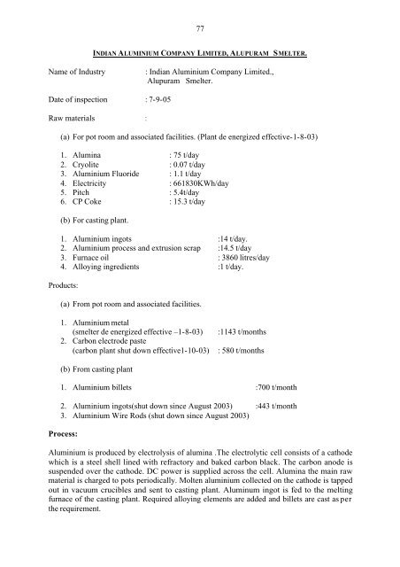
INDIAN ALUMINIUM COMPANY LIMITED, ALUPURAM SMELTER.<br />
Name of Industry<br />
: <strong>Indian</strong> <strong>Aluminium</strong> <strong>Company</strong> <strong>Limited</strong>.,<br />
<strong>Alupuram</strong> <strong>Smelter</strong>.<br />
Date of inspection : 7-9-05<br />
Raw materials :<br />
(a) For pot room and associated facilities. (Plant de energized effective-1-8-03)<br />
1. Alumina : 75 t/day<br />
2. Cryolite : 0.07 t/day<br />
3. <strong>Aluminium</strong> Fluoride : 1.1 t/day<br />
4. Electricity : 661830KWh/day<br />
5. Pitch : 5.4t/day<br />
6. CP Coke : 15.3 t/day<br />
(b) For casting plant.<br />
1. <strong>Aluminium</strong> ingots :14 t/day.<br />
2. <strong>Aluminium</strong> process and extrusion scrap :14.5 t/day<br />
3. Furnace oil : 3860 litres/day<br />
4. Alloying ingredients :1 t/day.<br />
Products:<br />
(a) From pot room and associated facilities.<br />
1. <strong>Aluminium</strong> metal<br />
(smelter de energized effective –1-8-03)<br />
2. Carbon electrode paste<br />
(carbon plant shut down effective1-10-03)<br />
:1143 t/months<br />
: 580 t/months<br />
(b) From casting plant<br />
1. <strong>Aluminium</strong> billets :700 t/month<br />
2. <strong>Aluminium</strong> ingots(shut down since August 2003) :443 t/month<br />
3. <strong>Aluminium</strong> Wire Rods (shut down since August 2003)<br />
Process:<br />
<strong>Aluminium</strong> is produced by electrolysis of alumina .The electrolytic cell consists of a cathode<br />
which is a steel shell lined with refractory and baked carbon black. The carbon anode is<br />
suspended over the cathode. DC power is supplied across the cell. Alumina the main raw<br />
material is charged to pots periodically. Molten aluminium collected on the cathode is tapped<br />
out in vacuum crucibles and sent to casting plant. Aluminum ingot is fed to the melting<br />
furnace of the casting plant. Required alloying elements are added and billets are cast as per<br />
the requirement.
78<br />
Solid Waste generation:<br />
1. There are two main hazardous wastes generated from the electrolytic cells.<br />
a. Gaseous fumes containing fluorides and alumina dust. This is led to wet scrubber<br />
for removal of fluoride and dust. The removed fluoride is neutralized using lime<br />
and filtered. This scrubber sludge is land filled. Quantity of the same is 1000t/year<br />
as per the authorization issued by KSPCB.<br />
b. Another hazardous waste originates is from cathodes. The carbonaceous lining<br />
degenerates after an age of 1500 to 2000 days. Upon this the lining is demolished.<br />
This waste is called spent pot lining. Quantity of waste is 700 t/year and is stored<br />
in building under cover on concrete pits.<br />
c. Lead acid batteries retired from mobile equipments. This comes to 50 numbers per<br />
year. Lead acid batteries are sold to authorized vendors or to the manufacturers.<br />
d. Waste asbestos used as thermal insulation. Quantity of Asbestos waste is 1 t/year<br />
which is land filled.<br />
e. Spent bricks.<br />
Refractory and fire bricks of failed pots are removed as and when required.<br />
Quantity of this waste is 150 t/year as per the authorization issued by KSPCB.<br />
2. Waste generation from casting plant. The following hazardous wastes are generated from<br />
this plant.<br />
a. <strong>Aluminium</strong> Dross.<br />
b. Oil containing sludge and oil emulsion.<br />
c. Lubricating oil and System oil.<br />
<strong>Aluminium</strong> dross is oxides of aluminium, generated during the time of melting. Quantity<br />
of the waste is 120 t/year. Generation of oil containing sludge is 1.5 t/year and<br />
Lubricating /system oil is 2 t/year.<br />
All the above wastes are disposed by sale to authorized re- processors.<br />
3. Water Consumption and Liquid waste:<br />
The industry now consumes 1140 KL of water per day. According to the consent<br />
issued by KSPCB the quantity of effluent discharged through outlet No.A is<br />
20,50,000 litres/day and through outlet no B is 6,50,000 litres /day. This quantity<br />
is based on water consumption when the unit was working in full swing. Now the<br />
industry is closed. The outlet A is to Periyar River which discharges effluent<br />
from bath rooms and other washings .The outlet B is over flow from cooling<br />
water tank which is discharged into land for percolation. During inspection there<br />
was some effluent discharge through the outlet A.<br />
Findings/ Recommendations:<br />
1. The industry had de energized the smelter and associated facilities effective 1 st<br />
august 2003.<br />
2. There is no waste generation from the smelter since the above period.<br />
3. The carbon electrode paste plant was shut down effective 1 st October 2003.<br />
4. Hazardous waste from the scrubber generated prior to the above period is seen<br />
land filled.<br />
5. Spent pot lining is seen stored carelessly in the industrial building.<br />
6. Spent bricks are also seen stored carelessly inside the industrial building.<br />
7. Oil containing sludge /lubricating oil/system oil are seen stored inside the<br />
plant building. This is disposed by sale to authorized reprocessors.
79<br />
8. The industrial plant was not working and hence there was no effluent<br />
generation.<br />
9. <strong>Company</strong> has obtained consent under the Water Act (to be renewed), consent<br />
under the Air Act and authorization under the Hazardous Waste (Management<br />
and Handling) Rules 1989.<br />
10. The monitoring well is to be relocated close to the capped pond to ascertain<br />
the leachate. The present inspection well in oversized and wide open which<br />
is totally unreliable to test leachate. These wells should be closed.<br />
11. The company has to renew the consent from KSPCB before restarting<br />
production.<br />
12. The sample taken from inspection well indicates fluoride content 2.26 mg/l<br />
which indicate ground water contamination. Even open wells of nearby<br />
residents indicates fluoride contamination. Therefore the unit must take<br />
necessary measure to prevent leachate from the disposal site.<br />
13. The unit on functioning in full swing , there would be good number of<br />
employees using canteen . There should be Effluent Treatment Plant for<br />
treating canteen waste.<br />
14. This is a unit which should go for zero discharge, since major discharge is<br />
overflow from cooling tower.<br />
Consented Parameters and limits<br />
Consented parameters under Water(Prevention and Control of Pollution)Act 1974.<br />
SL.No Characteristic Unit Tolerance<br />
limit<br />
Outlet A<br />
1. pH 5.5-9<br />
2. Suspended Solids mg/l 100<br />
3. Dissolved solids ,, 2100<br />
4. Sulphates ,, 1000<br />
5. Fluoride ,, 2<br />
6. Oil and Grease ,, 10<br />
7. Free Ammonia ,, 5<br />
8. Ammoniacal Nitrogen 50<br />
9. Zinc ,, 5<br />
10. Bio Chemical Oxygin Demand 30<br />
11. Nickel (as Ni) 3<br />
12. Chromium 2<br />
13. Copper(as Cu) 3<br />
14. Lead 0.1<br />
15. Outlet B<br />
16. PH -- 5.5-9<br />
17. Suspended Solids mg/l 200<br />
18. Bio Chemical Oxygin Demand 100<br />
19. Dissolved solids 2100<br />
20. Oil and Grease 10
80<br />
INDIAN ALUMINIUM COMPANY- EXTRUSION DIVISION<br />
Name of industry<br />
: <strong>Indian</strong> <strong>Aluminium</strong> <strong>Company</strong>- Extrusion<br />
division<br />
Date of inspection : 7-9-05<br />
Raw materials. :Aluminum billet :1200 t/month<br />
Electricity : 27356 KW h/day.<br />
Products<br />
: Aluminum extruded sections :840 t/month.<br />
Aluminum extruded scrap :360t/month<br />
Production Process.<br />
<strong>Aluminium</strong> extrusion is produced by squeezing a pre heated aluminium billet at a high<br />
pressure through an orifice of required shape in a steel die. Aluminum and its alloys are soft<br />
and plastic in temperature between 400 o C to 550 o C.The material can be easily extruded in the<br />
above temperature range. <strong>Aluminium</strong> scrap generated in the process is sent to the smelter<br />
section for reprocessing into billets.<br />
Solid waste generation.:<br />
Lead acid battery –5 nos/year. Used battery is stored in shed with roof and concrete floor.<br />
This is disposed by selling back to the suppliers.<br />
Quantity of spent lubricating and system oil comes to 5 t/year as per authorization issued by<br />
KSPCB. There is a facility for storing this in steel drums in shed with roof and concrete floor.<br />
Disposal of the material is by selling to approved reprocessor.<br />
Water consumption and Liquid waste generation<br />
The industry consumes 104 m 3 of water/day. They have provided facility for reusing cooling<br />
water used in the plant. The overflow from the cooling water tank is discharged into Periyar<br />
River. The quantity of effluent discharged from the plant is 15000 litres /day as per the<br />
consent issued by KSPCB.<br />
Findings/ Recommendation:<br />
1. Used lead acid battery is disposed by selling back to suppliers.<br />
2. Hazardous waste generated (spent lubricating and system oil) is seen stored in steel<br />
drums.<br />
3. There is facility for recycling of cooling water.<br />
4. There is overflow from the cooling water storage tank which is discharged through<br />
the outlet to Periyar River.
81<br />
5. Industry has obtained consent under the Water (Prevention and Control of Pollution)<br />
Act 1974(to be renewed) and authorization under Hazardous Waste (Management and<br />
Handling) Rules 1989 from KSPCB<br />
6. The company has to renew the consent under the Water (Prevention and Control of<br />
Pollution) Act 1974.<br />
7. The unit should obtain zero discharge as its main discharge is from overflow of<br />
Cooling tower.<br />
Consented Parameters and limits<br />
Consented parameters under Water(Prevention and Control of Pollution)Act 1974.<br />
SL.No Characteristic Unit Tolerance<br />
limit<br />
1. PH 5.5-9<br />
2. Suspended Solids mg/l 100<br />
3. Temperature<br />
0 C max<br />
4. ,,<br />
5. ,,<br />
Analysis Reports of the Effluent/ Sludge.<br />
shall not<br />
exceed 5 0 C<br />
above the<br />
receiving<br />
water<br />
temperature.<br />
Source<br />
: <strong>Indian</strong> <strong>Aluminium</strong> <strong>Company</strong> <strong>Limited</strong>.<br />
Date of sample collection : 7-9-05<br />
Sample Identification No :LAEC 172 (Outlet (Extrusion plant)),<br />
LAEC 147 (Outlet A),<br />
LAEC 197 (Inspection well (storage pit)),<br />
LAEC 199 (From well of Vincent),<br />
LAEC 49 (From well of flory George)<br />
Name of the Lab :Central Laboratory, K.S.P.C.B, Gandhi Nagar.<br />
Sl.<br />
No.<br />
Determinant Unit LAEC<br />
172<br />
LAEC<br />
147<br />
LAEC<br />
197<br />
LAEC<br />
199<br />
LAEC<br />
49<br />
1. PH 6.2 5.5 5.6 5.6 5.6<br />
2 BOD mg/l 0.18 0.2 0.12 0.18 0.12<br />
3 SS 7 8 7 8 12<br />
4 TDS 40 56 112 112 123<br />
5 Zinc ND ND ND ND 3.0<br />
6 Lead ND ND ND ND ND<br />
7 Copper ND ND ND ND ND<br />
8 Nickel ND ND ND ND ND<br />
9 Fluorides ND 1.3 2.26 0.36 0.9<br />
10 Sulphates ND 15 44 44 36
82<br />
11 Free Ammonia Nil Nil Nil Nil Nil<br />
12 Ammoniacal Nitrogen 0.44 ND ND ND 0.6<br />
13 Hexavalent Chromium ND ND ND ND ND<br />
14 Total Chromium ND ND ND ND ND<br />
15 Oil&Grease ND ND ND ND ND<br />
FACT, UYOGMANDAL. DIVISION<br />
Name of Industry<br />
:FACT, Uyogmandal. Division<br />
Date of inspection :01/06/05,08/07/05,30/07/05<br />
23/08/05,24/08/05<br />
Raw material :Naphtha 673 t/day<br />
:Rock Phosphate<br />
:Furnace oil<br />
Sulphur<br />
325 t/day<br />
135 t/day<br />
194 t/day<br />
Products<br />
: Sulphuric Acid - 600t/day Sulphuric acid and<br />
550tonnes/day combined capacity SO 2 /acid<br />
: Ammonia -900t/day<br />
: Phosphoric acid -100t/day<br />
: Ammonium Sulphate -682t/day<br />
: Ammonium Phosphate - 450 t/day<br />
: Carbon dioxide -1007t/day<br />
: Gypsum - 500 t/day<br />
Production Process:<br />
1.Sulphuric Acid.<br />
The process consists of Sulphur melting, Combustion of sulphur-to-sulphur dioxide, Catalytic<br />
conversion of sulphur dioxide to get sulphur trioxide, Intermediate absorption of Sulphur tri<br />
oxide in concentrated Sulphuric acid to produce Sulphuric Acid, Final conversion of<br />
unreacted Sulphur dioxide to Sulphur trioxide and final absorption of Sulphur trioxide in<br />
concentrated Sulphuric Acid.<br />
The converter consists of four beds of vanadium pentoxide catalyst. The gas from the furnace<br />
after passing through the waste heat boilers enters the first bed at 430 o C.In the first layer<br />
about 57% of SO 2 is converted and the gas leaving the first bed is cooled from 594 o C to<br />
440 o C in the waste heat boiler, and then enters the second bed where the conversion reaches<br />
85% and the temperature raises to 520 o C which is brought down to 450 o C in Intermediate
83<br />
Heat Exchangers. The gas then goes to 3 rd bed where conversion reaches 94% and<br />
temperature to 475 o C.The gas goes to the final heat exchanger and then to the Intermediate<br />
Absorption Tower where SO 3 is absorbed and gas leaving the absorber at 65 o C enters the<br />
fourth bed at 420 o C after passing through the Final Heat Exchanger and then the Intermediate<br />
Heat Exchanger. The conversion reaches 99.5% and temperature 445 o C.The gas then goes to<br />
the final absorption tower through an economizer where the temp is brought down to<br />
180 o C.Gas from the final absorption tower is released to the atmosphere through the stack.<br />
Process water is admitted to the tower bottom to maintain the acid concentration at 98.4%.<br />
The acid drawn off from the final absorber is cooled to 40 o C and stored.<br />
2.Ammonia<br />
Process involved in the production of ammonia are :<br />
a. Predesulphurisation of the raw naphtha. The bulk part of sulphur is removed in this<br />
section.<br />
b. Final desulphurisation of the hydrocarbon feed in one step: Removal of remaining<br />
sulphur compounds.<br />
c. Reforming of the desulphurised hydrocarbon feed in two steps by steam and air. The<br />
process gas from these steps contains hydrogen and nitrogen as well as carbon<br />
monoxide (CO), carbon dioxide (CO 2 ), methane and argone. The reforming takes<br />
place at pressure of about 35kg/cm 2<br />
d. In the gas purification section, CO is first converted to CO 2 and H 2 yield. CO2<br />
is then removed in the CO 2 -removal section, and afterwards the remaining CO and<br />
CO 2 in the converted gas are removed in the methanator.<br />
e. The purified synthesis gas is compressed to a pressure of about 135kg/cm 2 and<br />
converted into ammonia by a catalytic reaction.<br />
f. The plant is designed to a nominal production of 900 MTPD ammonia and 10,800<br />
Nm3/H of synthesis gas. The ammonia produced in the plant is sent to the<br />
caprolactam plant and to atmospheric storage. Synthesis gas is consumed in the<br />
caprolactam plant as well, and in combination with part of the CO 2 produced.<br />
3.Phosphoric Acid<br />
Phosphoric acid is manufactured by wet process by the reaction of rock phosphate with<br />
sulphuric acid.<br />
The principal steps in the production of Phosphoric acid by this method are the following:<br />
Grinding of rock phosphate, Reaction of the ground rock with sulphuric acid, and Separation<br />
of phosphoric acid from the gypsum.<br />
(a) Grinding of rock phosphate: The phosphate rock is ground dry in mills after drying if<br />
necessary. There are three grinding mills with a total capacity of 40 tonnes/hr of<br />
ground ore. The rock is ground so that 95 per cent will pass through a 100-mesh<br />
screen.<br />
(b) Reaction of rock phosphate and sulphuric acid: The main aim of this step is to get the<br />
rock reacted with sulphuric acid in such a manner as to (1) produce the highest<br />
possible concentration of phosphoric acid, (2) give good coarse gypsum crystals<br />
which could be easily filtered and washed with minimum of water to give a washed<br />
gypsum almost free of soluble phosphoric acid and (3) give the maximum yield of<br />
P 2 O5 from the rock.
84<br />
The Dorr Oliver single tank reaction system is employed here.<br />
The slurry formed during the reaction is fed to the filter for separation of gypsum<br />
from phosphoric acid.<br />
Counter-current washing of the cake is carried out with 10 to 12% acid, secondly 3 to<br />
5% acid and finally with water. Wash acid of strength 19%is returned to the reaction<br />
system. The filtrate of strength 20 to 22% is sent to storage.<br />
The byproduct gypsum is slurried with water and pumped to the Sulphate plant.<br />
4.Ammonium Phosphate<br />
Phosphoric acid, Sulphuric acid and gaseous ammonia are fed to a saturator and<br />
agitated. Further addition of ammonia is done in the second saturator. The neutralized<br />
product is a thick slurry and flows to a blunger where it is mixed with undersized<br />
granules; crashed granules and recovered dust, along with some urea. The granulation<br />
takes place in the blunger.<br />
The liquid ammonia at a pressure of 15 psi (g) and 18 o C is injected to the blunger to<br />
adjust the mole- ratio to 1.8.The amount of dry material recycled to the blunger is<br />
about 6 to 10 tonnes per tonne of dry material produced .The blunger which operates<br />
which on fludisation technique is of a double shat paddle mixer set on a slope .The<br />
granulated wet product from the blunger flows through a chute to rotary co-current<br />
drier when the material is dried by a current air along with combustion products from<br />
a combustion chamber. The material leaving the drier is conveyed to set of vibrating<br />
screens with 8 and 14 mesh screens. The –8 and +14 material is taken out as the<br />
product. The +8 material is crushed and, along with –14-mesh material is fed back<br />
into the blunger .The hot airflow is maintained through the driver by fan. The dustladen<br />
air leaving the drier fan passes through a multiple cyclone where the bulk of the<br />
dust separates out. The dust coming from the screens and other equipments is driven<br />
out by a dust fan through a cyclone. The air from the drier cyclone and dust cyclone<br />
along with the fumes leaving the reaction tank enter the scrubbers for removal and<br />
recovery of ammonia and dust. The scrubbing is done with phosphoric acid. The<br />
scrubber solution is fed back to the reaction tank. The product is bagged and sent to<br />
storage.<br />
5.Ammonium Sulphate<br />
The Ammonium sulphate solution fed to the unit consisting of two separate streams<br />
from the Caprolactum Plant of Petrochemical Division .One feed stream is Lactum<br />
ammonium sulphate solution and the other feed stream is Oxime ammonium sulphate<br />
solution. This plant consists mainly of the following four sections.<br />
1. Concentration and crystallization section<br />
2. Dewatering section<br />
3. Drying and cooling section<br />
4. Storage and bagging section.
85<br />
1. Concentration and crystallization section:<br />
The quadruple effect crystalliser and evaporator system with one concentrator are<br />
used for this purpose. First effect consists of two evaporators, one for oxime and the<br />
other for Lactum ammonium sulphate solutions. Second and third effects are the<br />
oxime ammonium sulphate crystallizers, and fourth effect is lactam ammonium<br />
sulfate crystallizers.<br />
The 40 % Oxime Ammonium sulphate solution is fed into 1 st Effect Oxime<br />
Ammonium sulphate Evaporator after preheating at Oxime Ammonium sulphate.S pre<br />
heater and solution is concentrated to approx. 51-wt % of ammonium sulphate.<br />
The concentrated solution is sent to No.1 Oxime Ammonium sulphate crystalliser. A<br />
half of ammonium sulphate contained in Oxime Ammonium sulphate solution is<br />
crystallized in this crystalliser and the slurry (approx.30 wt %) is sent to dewatering<br />
section. The rest mother liquor overflows to No.2 oxime Ammonium sulphate<br />
crystallizer where ammonium sulphate is crystallized and the slurry is sent to be<br />
dewatering section.<br />
To prevent accumulation of impurities mainly composed of ammonium nitrate in the<br />
system and to keep product quality, a portion of mother liquor is purged from No.2<br />
Oxime Ammonium sulphate Crystallizer.(V4) 40% Lactum ammonium sulphate<br />
solution is fed to concentrator Cyclone Underflow tank where lactam Ammonium<br />
sulphate solution dissolves dirty crystals. The mother liquor is fed to 1 st Effect Lactum<br />
Ammonium sulphateEvaporator (V-2) be concentrated to approx.46 wt %. The<br />
concentrated solution is sent to Lactum Ammonium Sulphate crystallizer(V-5) and<br />
the slurry containing high impurities is sent to S-3 Concentrator Cyclone.<br />
2. Dewatering section:<br />
There are 5 numbers of continuous pusher type centrifuges used for dewatering of,<br />
ammonium sulphate crystals. Oxime ammonium sulphate slurry is thickened in a<br />
prethickner. In the Centrifuges crystals are washed by vapor condensate and<br />
dewatered simultaneously. Dewatered product crystals are then fed to the next drying<br />
section through two conveyors.<br />
Lactum ammonium sulphate slurry is thickened in cyclone and dewatered in<br />
centrifuge. The crystals are then sent to the dryer.<br />
3. Drying and cooling section:<br />
Both of oxime and lactam sulphate crystals from the centrifuges are fed to Dryer<br />
Cooler through conveyor. One dryer-cooler is in service and an integrated design of<br />
dryer and cooler is applied. Both dryer and cooler are fluidized bed type. The wet<br />
crystals are dried by hot air generated in Hot Air Heater. Then, the hot dried crystals<br />
are cooled down to approx.55 o C by direct air-cooling and indirect heat exchanger<br />
installed inside the cooler.<br />
4. Storage and Bagging section:<br />
The crystals are then fed to hopper A or B by Product Conveyor. Dehumidified Air is<br />
fed to the Hoppers to prevent caking of the hygroscopic Ammonium Sulphate<br />
crystals.The crystals are bagged using four bagging machines.
86<br />
Waste<br />
The effluent generated in various plants of the factory are treated in the effluent treatment<br />
plants and discharged through three outlets.<br />
The company has obtained Boards consent under the water act for discharging 12,000-<br />
m 3 /day effluents through outlet no. A into River Periyar, 5000 m 3 /day effluent through outlet<br />
no. E into Kuzhikandam thodu, and 4800 m 3 /day effluent through outlet No.I into Edamula<br />
branch of River Periyar.<br />
An Effluent treatment plant consisting of equalization, neutralization, clariflocculation and<br />
ammonia stripping are provided for treating the effluent from sulphuric acid plant,<br />
Ammoniam Sulphate, Ammonium Phosphate and Phosphoric acid plants. The treated<br />
effluent is discharged through outlet No. A into Periyar river. The new complex Ammonia<br />
plant effluents are collected separately for neutralization and settling before taking to the<br />
guard ponds from where it is discharged through the outlet I in to the Edamula branch of<br />
Periyar river. Outlet carrying storm water and various condensate from ammonium sulphate<br />
plant are discharged into Kuzhikandam thodu through open drain in the premises of M/s<br />
HIL.(Outlet No. E)<br />
The company has obtained Board’s consent under the Air Act for making emissions<br />
through14 stacks from process plants and 2 stacks from captive Power plant.<br />
Hazardous wastes generated from the factory are spent catalyst from sulphuric acid plant and<br />
ammonia complex, sulphur muck from sulphuric acid plant, gypsum from phosphoric acid,<br />
and sludge from effluent treatment plant. The company has obtained authorization under<br />
Hazardous Waste (Management and Handling) Rules 1989 for the disposal of (a) 40 t/year<br />
spent catalyst by sale or transfer to person possessing valid authorization from Board. (b)<br />
1300 t/year sulphur containing residue in disposal area and 20-t/year waste oil to authorized<br />
recycler.<br />
Findings.<br />
1. Source of water is Periyar River and the treated water from a common water treatment<br />
plant meets the requirement of FACT-UDL, FACT-PD and FACT Township. Treated<br />
water is also supplied by FACT to other neighbouring industries. According to the<br />
company total water consumption in Udyogamandal division is 26522 KL<br />
2. Sulphuric acid plant was inspected on 30-07-05.There are two sulphuric acid plants<br />
600 tpd DCDA plant producing 400-t/day sulphuric acid and 200-t/day oleum, and the<br />
new plant producing 375t/day So 2 and 175-tpd sulphuric acid. Both the plants have<br />
DCDA conversion process for converting SO 2 to SO 3 .<br />
3. During the time of inspection 600 tpd sulphuric acid plant called DC DA plant was<br />
under shut down. Online SO 2 monitor is installed in the sulphuric acid plant. The So 2<br />
Monitor in DCDA acid plant is seen not working since 26/7/05. On July 7 th , the date<br />
of occurrence of gas leakage and fugitive emission from DCDA sulphuric acid plant,<br />
the monitor recorded the upper range value of 1000 ppm, the manual stack analysis<br />
data showed 1373 ppm.<br />
4. Production capacity of the Ammonium sulphate plant is 682 t/day. The company<br />
authorities informed that 30% ammonium sulphate solution brought from FACT-
87<br />
Petro chemical Division is concentrated, crystallized, centrifuged, dryed and cooled to<br />
produce ammonium Sulphate. The vapour condensate is used to produce ammonia in<br />
the HYAM plant of FACT-Petro Chemical Division and the purge liquid containing<br />
30% ammonium sulphate is reused in the plant.<br />
5. Overflow of vapour condensate storage tank and spillage are taken to a collection pit<br />
and pumped to effluent treatment plant. A level controller is provided in the pit. The<br />
storm water drains and vapour condensate from ammonium sulphate plants are found<br />
leading to a marshy land near old ammonia plant and finally discharge into<br />
Kuzhikandam thodu through an open drain ie, outlet no: E through the premises of<br />
HIL.Immense flow was noticed through the outlet, which according to the company<br />
authorities was due to storm water infiltration in cable trenches. The effluent through<br />
the drain is seen contaminated with high pH.<br />
The monitoring data indicates that SO 2 levels are often exceeded. The emission from<br />
both the acid plant are let out through one stack.<br />
6. The ladder provided for monitoring SO2 emission through sulphuric acid plant stack<br />
is not being used. The company authorities informed that the manual stack sampling<br />
is done by collecting the air sample through hose connection at ground level.<br />
7. One storm water drain from the factory premises leading to the Northwest corner,<br />
after crossing the road passes through the property of M/S.IRE Ltd (hazardous waste<br />
disposal area) and joins Kuzhikandom thodu before the discharge point of HIL. This<br />
drain of the company is seen carrying Gypsum on many occasions.<br />
8. The effluents from the complex ammonia plant are taken to guard pond after<br />
neutralization and discharged into the Edamula branch of Periyar River through outlet<br />
No.1.A pH meter is installed at the neutralization tank. Arrangement is provided for<br />
returning the effluent back to neutralization tank incase the quality of effluent in the<br />
guard pond is beyond limits. Online pH meter is installed at the guard pond.<br />
9. The phosphoric acid plant ammonia complex and ammonium phosphate plants are the<br />
major sources of liquid effluent. Ammonia complex effluents are treated separately<br />
and discharged. The liquid effluents from sulphuric acid, phosphoric acid ammonium<br />
phosphate and ammonium sulphate plants are taken to the effluent treatment plant<br />
consisting of equalization tank having two compartments, flash mixer, clariflocculator<br />
and ammonia stripper. The effluent generated from various plants are collected in a<br />
collection tank inside the plant before admitting to the equalization tank. The under<br />
flow from the clariflocculator is returned to the equalization tank. Accumulated<br />
sludge from the equalization tank is removed using crane and dumped nearby for<br />
dewatering. The surface run off from the dumping area is taken to the equalization<br />
tank. . The dewatered sludge is taken to LDPE lined Gypsum disposal yard of the<br />
factory approved by the Board, which is away from the factory site.<br />
10. An oil trap provided in the storm water drain in boiler plant near oil handling area is<br />
seen not functioning.<br />
11. The phosphoric acid plant is not working. Imported acid is used for the production<br />
purpose.<br />
12. The company authorities informed that the scrubbed liquid from ammonium<br />
phosphate plant is taken to collection tanks for recirculation. Recirculation<br />
arrangements are provided for reusing the scrubbed liquor from ammonium phosphate<br />
plants.<br />
13. The scrubbed liquid from IV th stage ammonium phosphate plant is seen containing<br />
oil and black particles. The downward dispersal of emissions from scrubber stacks of<br />
the (300tpd) IV th stage ammonium phosphate plant close to TCC boundary is creating
88<br />
air pollution problems of poor visibility, mist and fog formation and health effects in<br />
the <strong>Eloor</strong> Edayar industrial area.<br />
14. The company has obtained Board’s consent under the Water Act for discharging<br />
12000m 3 /day effluent through outlet no.A. into Periyar River, 5000m3/day effluent<br />
through outlet E into Kuzhikandom thodu, and 4800 m3/day through outlet no: 1into<br />
Edumula branch of Periyar River.<br />
15. The hazardous wastes generated are spent catalyst, sulphur muck, spent lubricating oil<br />
and system oil, and sludge from effluent treatment plants. Of these spent catalyst such<br />
as zinc and nickel are disposed by sale to authorized dealer and spent vanadium<br />
catalyst as hazardous waste in disposal site. Sulphur muck is stored for disposal in<br />
approved disposal area. Effluent Treatment Plant sludge and filter cakes of phospho<br />
gypsum from gupsum filters are stored in intermediate storage for final disposal in<br />
LPDE lined gypsum yard. As per the Environmental statement furnished by the<br />
company for 2003, the quantity of wastes handled were<br />
sulphur muck-1158t/year<br />
spent catalyst-65t/year<br />
waste oil -17t/year<br />
ETP sludge -2125.62t/year.<br />
16. Low chromate treatment system is adopted for treating cooling water. It is informed<br />
that the company have programme for changing cooling tower treatment system from<br />
low chromate to non-chromate system in Ammonium Sulphate plant.<br />
17. Raw material Sulphur spilled over during material handling near the unloading area is<br />
reaching the river along with surface run off. The company have already taken some<br />
steps for containing the spillage of sulphur particles escaping through the drain.<br />
18. Effluent samples were collected from various plants ,effluent treatment plant and<br />
outlets for analysis.<br />
19. The company authority informed that they have proposals for improving the quality<br />
of effluent and elimination of storm water contamination.<br />
Recommendation :<br />
a. Proposed to modify the effluent treatment during 2005 in a phased manner.<br />
b. Scheme for diversion of vapour condensate from new ammonium sulphate<br />
plant to phosphoric acid plant by 2006. But there is no production of<br />
phosphoric acid.<br />
c. Scheme for diverting storm water from pollution control plant area.<br />
d. Scheme for elimination of E drain, to be commissioned by March 2006.<br />
1. Effluent treatment plant is to be augmented incorporating measures for reducing<br />
ammoniacal nitrogen content and effective control over the addition of treatment<br />
chemicals, sludge removal, dewatering, and disposal.<br />
2. Delay pond shall be provided in all storm water drains with monitoring facility.<br />
3. Steps shall be taken for reducing the water consumption, effluent generation and<br />
achieving zero effluent discharge system.<br />
4. Adequate steps shall be taken to prevent the escape of gypsum through storm water<br />
drains.<br />
5. Oil traps in storm water drains are to be revamped and made functional.<br />
6. Adequate steps for effective control of S02 emission through Sulphuric acid plant<br />
stacks shall be taken.
89<br />
7. The scrubber stack for IVth ammonium phosphate plant 150 t/day is seen creating<br />
severe air pollution problems. Adequate control measures such as increasing stack<br />
height and emission velocity shall be provided.<br />
8. Stack monitoring facilities should be renovated and sampling should be done by<br />
drawing sample at the sampling point.<br />
9. Arrangement for avoiding the spillage of sulphur into the storm water drain shall be<br />
provided.<br />
10. Sealed Water meters shall be installed at the raw waters intake point in Periyar River<br />
to measure the water consumption by FACT-UDL, township and FACT-PD separately.<br />
11. The Board should direct the company to install sealed water meter at the intake point<br />
and collect water cess according to the reading in the meter . There should be<br />
periodic for reading water meter.<br />
12. Remedial measure to prevent spillage by overflow of sulphuric acid to avoid leading<br />
to periyar.<br />
13. The discgharge from FACT through outlet E be located near the first culvert over the<br />
Kuzhikandam thodu and made visible and accessible.<br />
14. The company should conduct a safety audit with the competent agency periodically.<br />
2 nd report on FACT Udyogamandal Division<br />
(Extracts of 70 th meeting held on 29-06-2005)<br />
Resolution no. 1<br />
Mr. Purushan <strong>Eloor</strong>, Member LAEC reported that an incident of fugitive emission on 26-6-<br />
2005 at <strong>Eloor</strong> Vadakumbagam where a public sector undertaking namely FACT<br />
Udyogamandal situate. Huge white smoke spread around the area caused severe discomfort<br />
for breathing, throat irritation and vomiting sensation to the residents of Kanjirakuzhi and its<br />
northern area of <strong>Eloor</strong> Panchayat.<br />
The fugitive emission is believed to be from FACT and, by the description of discomfort felt<br />
to the people, the fugitive emission contained sulphur dioxide and sulphuric acid mist. The<br />
smoke burned even the leaves of the trees. Some residents were treated in the Primary Health<br />
Center, <strong>Eloor</strong>.<br />
The reported fugitive emission was duly informed at the office of the Pollution Control<br />
Board Ernakulam. LAEC members Mr. Purushan <strong>Eloor</strong>, Jacob.V.Lazar and official of<br />
Pollution Control Board Mr. K.S.Soman AEE inspected the affected area and took statements<br />
from the residents on the incident. The report of the inspection is read over in the meeting and<br />
is made part of this proceeding.<br />
The committee deliberated on various aspects of the incident and expressed its anxiety on the<br />
lack of arrangements for attending to such incidents, which is part of the comprehensive<br />
chemical disaster management. The committee has been alerted on the fact that despite <strong>Eloor</strong>-<br />
Edayar industrial belt being an area with number of chemical industries dealing in hazardous<br />
chemicals, a program for chemical disaster management is indispensable and the same is yet<br />
to be evolved.
90<br />
The district administration, Factories and Boilers and Pollution Control Board should evolve<br />
a scheme for chemical disaster management for <strong>Eloor</strong> - Edayar and periodical review is to be<br />
made. The residents of <strong>Eloor</strong> –Edayar should also be educated and necessary training be<br />
given.<br />
Committee resolved to approach the district collector and seek his indulgence for constitution<br />
of such a body. Mr. Purushan <strong>Eloor</strong> and Mr.Asokan are authorized to meet the collector and<br />
to follow up the matter.<br />
3 rd report on FACT Udyogamandal Division<br />
(Extracts of the 72 nd meeting held on 9-7-2005)<br />
Resolution No.1<br />
LAEC members as part of the stack monitoring inspected FACT, Udyogmandal along with<br />
the officials of PCB viz., Mr. K.S. Soman, Asst. Environmental Engineer; Mr. K.V.<br />
Shanavas, Asst. Scientist on 8 th July, 2005 at 12:30 p.m.<br />
The inspecting team before arriving at FACT had received complaints from local people<br />
including industrial workers regarding suffocation, chest congestion etc., as a result of serious<br />
fugitive emission, which was found visible in areas near Sud-Chemie, Binani Zinc Ltd.,<br />
Njavallil Latex and other areas in the Edayar industrial belt. A survey conducted by the<br />
inspecting team in these areas revealed that the source of emission is from FACT,<br />
Udyogamandal and people have been suffering such discomforts for the past few days. It may<br />
be recalled that a large scale emission, which caused serious apprehension in the minds of the<br />
people by the fugitive emission happened on 26/06/2005 was taken note of and this<br />
Committee had resolved to request PCB for necessary action against FACT, Udyogamandal,<br />
being the culprit of fugitive emission.<br />
Mr. Baburaj, Asst. Environmental Engineer of PCB joined the inspecting team at 1:30 p.m. at<br />
FACT, Udyogamandal. FACT, Udyogamandal Acid Plant was inspected by the team as the<br />
concern of the team was to find out the source of SO 2 & SO 3 (Sulphur dioxide and sulphur<br />
tri-oxide) emission. The FACT claims to have on-line recorder for stack monitoring. The<br />
said system for stack no. 15 (Acid plant) was found to be operational. The needle of the<br />
recorder is found remaining at the maximum point viz., 1000 ppm, which is equivalent to<br />
2617 mg/nm 3 as against the permissible concentration of 1500 mg/nm 3 .<br />
The emission through the stack being highly in excess of the permissible limit, which is even<br />
beyond the comprehension of the installed on-line recorder was detected as a serious lapse<br />
causing very grave concern to the environment and local community. The complaints of the<br />
local community and from the nearby industrial community stands vindicated by the above<br />
findings of LAEC. The inspecting team asked the <strong>Company</strong> to furnish the statement of online<br />
recorder for previous 7 days on-line monitoring. The company refused to provide the<br />
same on the plea that they have a Chemical Analysis Report of Manual analysis of checking<br />
concentration of pollutants. The inspecting team then asked as to how a manual analysis is<br />
conducted. The company confessed that the manual analysis is not done from the stack<br />
inspection duct by climbing at the sample point. According to them, the ladder provided for<br />
climbing is rusted and not safe enough to use the same. The sample is therefore collected<br />
from a pipe connected to the duct of the chimney. When confronted by the LAEC, as to how<br />
samples were taken from pipe can give the pressure of the emission, the company admitted
91<br />
the faulty nature of manual analysis. The laboratory reports of the manual analysis furnished<br />
to the LAEC is thus found to be unreliable. Despite insisting for the on-line recorder<br />
statement, the same has not been furnished.<br />
The company is not having adequate system to control the fugitive emission and even the<br />
system provided for recording the emission is found totally inadequate. The <strong>Company</strong> has<br />
not provided necessary arrangement even to the regulatory machinery to monitor the Stack.<br />
The provisions of the Air Act and the conditions of the Consent issued to the <strong>Company</strong> is<br />
thus found violated with impunity.<br />
During the inspection, Mr. Dandapani, Plant Manager was present throughout. After the<br />
inspection, the inspecting team also met Mr. Asokan, General Manager and appraised him of<br />
the situation and the concern of the LAEC.<br />
After the inspection, Chairman, LAEC had a telecon with the General Manager, FACT in the<br />
evening to inform him that any future complaints on fugitive emission from the locals would<br />
be seriously viewed and that the company should immediately arrest the emission beyond the<br />
consent parameters. Mr. Asokan, General Manager, FACT assured that necessary<br />
precautionary steps will be taken up.<br />
Despite these warnings, the <strong>Company</strong> could not control fugitive emission and as a result at<br />
around 10:30 p.m., Chairman, LAEC was informed by members of LAEC, Mr. Asokan and<br />
Mr. Jacob Lazer that they are patrolling in <strong>Eloor</strong> / Edayar belt on information that there is<br />
huge smoke in the entire area and some unit is on fire. The workers in the industrial belt was<br />
found panicky. LAEC members, surveilled the entire area and found 3 fire force engines,<br />
police force and the <strong>Eloor</strong> Panchayath President, Smt. Subaida Hamsa were all moving in the<br />
Industrial area to identify the source of wide spread white smoke. LAEC members, local<br />
community and industrial workers felt suffocation. The major source of this emission was<br />
ultimately found to be from FACT, Udyogamandal.<br />
In the above circumstances, LAEC resolved to recommend that the operation of the Acid<br />
Plant of FACT, Udyogamandal be directed to stop production forthwith and be allowed to restart<br />
production only after ensuring that the Unit makes adequate and fool-proof pollution<br />
control measures to the satisfaction of LAEC and PCB.
93<br />
Analysis Reports of the Effluent/ Sludge.<br />
Colour code<br />
Red: Pollutants not conforming to the standards stipulated in consent order.<br />
Pink: Pollutants in effluent not included in consent order<br />
Dark red: Pollutants in hazardous waste /sludge exceeding limit as per HW Rules.<br />
Blue: Presence of heavy metals/pollutants in hazardous waste/sludge.<br />
Source<br />
: FACT – UD<br />
Date of sample collection : 24-8-05<br />
Sample Identification No : LAEC 210(Combined Effluent Ammonium Phosphoric Acid<br />
Plant (300 TPD plant)),<br />
LAEC 202 (Ammonium phosphate collection pit 150 TPD<br />
plant),<br />
Name of the Lab :Central Laboratory, K.S.P.C.B, Gandhi Nagar.<br />
Sl.<br />
No.<br />
Determinant Unit LAEC 210 LAEC<br />
202<br />
Tolerance<br />
Limit<br />
1. pH 2.14 6.7 6.5-8.0<br />
2 BOD mg/l 1.2 0.8 -<br />
3 COD ,, 32 32 -<br />
4 SS ,, 22 15 100<br />
5 TDS ,, 1329 135 --<br />
6 Arsenic ,, ND ND --<br />
7 Chlorides ,, 200 80 --<br />
8 Fluorides ,, 27.2 2.8 1.5<br />
9 Nitrates as Nitrogen ,, 0.36 0.23 20<br />
10 Phosphates ,, 560 25.4 5<br />
11 Sulphates ,, 190 40 -<br />
12 Cyanides ,, ND ND 0.2<br />
13 Free Ammonia ,, Nil 0.098 4<br />
14 Total kjeldhal Nitrogen ,, 140.2 19.9 150<br />
15 Ammoniacal Nitrogen ,, 137 19.5 75<br />
16 Phenolic compounds ,, 1.55 0.84 -<br />
17 Hexa valent Chromium ,, ND ND 0.1<br />
18 Total Chromium ,, ND ND 2<br />
19 Oil & grease ,, ND ND 10<br />
20 Vanadium ,, ND ND 0.2
94<br />
Source<br />
: FACT – UD<br />
Date of sample collection : 24-8-05<br />
Sample Identification No : LAEC 212(Spillage pit (New NH 4 SO 4 plant)),<br />
LAEC 204(Guard pond(Ammonia Complex)),<br />
LAEC 168(Edrain(Collection sump))<br />
Name of the Lab<br />
:Central Laboratory, K.S.P.C.B, Gandhi Nagar.<br />
Sl.<br />
No.<br />
Determinant<br />
Unit Spillage<br />
pit<br />
(New<br />
NH 4 SO 4<br />
plant<br />
Guard pond<br />
(Ammonia Complex<br />
Tolerance<br />
limit<br />
1. pH 8.2 6.7 6.5-8 5.8<br />
2 BOD mg/l 0.8 4.2 - 0.8<br />
3 COD ” 14.7 48 - 8.3<br />
4 SS ” 8.0 8.0 100 12<br />
5 TDS ” 255 1548 -- 240<br />
6 Arsenic ND ND -- ND<br />
7 Fluorides 0.13 0.19 1.5 0.14<br />
8 Chlorides 30 590 50<br />
9 Nitrates as<br />
7.0 4.0 20 0.45<br />
Nitrogen<br />
10 Phosphates ND 0.2 ND<br />
11 Sulphates 90 170 90<br />
12 Cyanides ND ND ND<br />
13 Free Ammonia 6.65 0.31 Nil<br />
14 Total kjeldhal 96.9 63.5 150 19.9<br />
Nitrogen<br />
15 Ammoniacal 95 62.3 75 19.5<br />
Nitrogen<br />
16 Phenolic<br />
2.1 2.4 2.6<br />
compounds<br />
17 Hexa valent<br />
ND ND ND<br />
Chromium<br />
18 Total<br />
ND ND ND<br />
Chromium<br />
19 Oil & grease ND ND ND<br />
20 Vanadium ND ND ND<br />
Edrain(Collection<br />
sump<br />
Source<br />
: FACT – UD<br />
Date of sample collection : 30-7-05<br />
Sample Identification No : LAEC 248(Final outlet),<br />
LAEC 249(Raw Effluent-1),<br />
LAEC 250(Sludge under flow),<br />
LAEC 251(Raw effluent-2)<br />
LAEC 252(Effluent before Ammonia removal)<br />
Name of the Lab :Central Laboratory, K.S.P.C.B, Gandhi Nagar.
95<br />
Sl.<br />
No.<br />
Determinant Unit LAEC<br />
248<br />
LAEC<br />
249<br />
LAEC<br />
250<br />
LAEC<br />
251<br />
LAEC<br />
252<br />
1 pH 6.9 4.6 8.0 3.2 9.2<br />
2 SS mg/l 15 52 22 47 8<br />
3 Arsenic ” ND ND ND ND ND<br />
4 Fluorides ” 1.39 21 2.42 68.2 0.76<br />
5 Nitrates as Nitrogen ” 0.33 0.369 7.09 0.06 0.22<br />
6 Phosphates ” 0.8 36O 1.2 1092 ND<br />
7 Sulphates ” 320 550 625 1100 750<br />
8 Cyanides ” ND ND ND ND ND<br />
9 TKN ” 74 222.4 61 513 118<br />
10 Ammoniacal Nitrogen ” 71 218 60 503 116<br />
11 Hexa Chromium ” ND ND ND ND ND<br />
12 Total Chromium ” ND ND ND ND ND<br />
13 Oil and Grease ” ND ND ND ND ND<br />
14 Vanadium ” ND ND ND ND ND<br />
Source<br />
: FACT – UD<br />
Date of sample collection : 30-7-05<br />
Sample Identification No : LAEC 253(Raw effluent After Primary settling),<br />
LAEC 254(Effluent after Ammonia removal),<br />
LAEC 255(Raw Effluent (inside plant))<br />
Name of the Lab :Central Laboratory, K.S.P.C.B, Gandhi Nagar.<br />
Sl.<br />
No.<br />
Determinant Unit LAEC<br />
253<br />
LAEC<br />
254<br />
LAEC<br />
255<br />
1. pH 5.8 8.8 5.2<br />
2 SS mg/l 8 10 162<br />
3 Arsenic ” ND ND ND<br />
4 Fluorides ” 5.2 0.87 81.6<br />
5 Nitrates as Nitrogen ” 0.27 0.25 0.43<br />
6 Phosphates ” 74 ND 4.4<br />
7 Sulphates ” 425 450 2000<br />
8 Cyanides ” ND ND ND<br />
9 TKN ” 112 72 766<br />
10 Ammoniacal Nitrogen ” 109 71 751<br />
11 Hexa Chromium ” ND ND ND<br />
12 Total Chromium ” ND ND ND<br />
13 Oil and Grease ” ND ND ND<br />
14 Vanadium ” ND ND ND
96<br />
FACT- PETROCHEMICAL DIVISION<br />
Name of the Industry<br />
:FACT- Petrochemical division<br />
Raw materials : Name Quantity(Avg. tones /day)<br />
1. Benzene 150<br />
2. Synthesis gas as Ammonia 79.5<br />
3. Caustic Soda (100 %) 19<br />
4. Sulphur Dioxide 213<br />
5. Ammonia 236<br />
6. Carbon dioxide 66.5<br />
7. Oleum as 100% sulphuric acid 210<br />
8. Furnace oil 175<br />
Products: Name Quantity(Metric tonne /day)<br />
Process:<br />
The production process consists of<br />
1. Benzene hydrogenation<br />
2. Cyclohexane oxidation<br />
3. Hydroxylamine sulphate preparation<br />
4. Oximation and Lactum preparation<br />
5. Lactum flaking and bagging<br />
1. Caprolactum 152<br />
2. Ammonium Sulphate (solution) 672<br />
3. Soda Ash 14<br />
4. 55% Nitric Acid 11.5<br />
Benzene hydrogenation Section: In this section, Benzene is catalytically hydrogenated to<br />
produce Cyclohexane.Benzene is first dried of any moisture contained in it by distillation. It<br />
is then vaporized, mixed with recycled gases from a subsequent section of the plant and fresh<br />
make-up hydrogen and passed through tubular reactors containing Platinum on Alumina<br />
catalyst. After convertion, Cyclohexane is condensed and separated and the uncondensed<br />
gases recycled back to reactors. A small amount of purge gas is released from the recycled<br />
gases to prevent build up of inerts. Heat of reaction is removed through heat transfer oil and<br />
is used to vaporize Benzene and also to generate steam.<br />
Cyclohexane Oxidation Section: Cyclohexane is oxidized with air to Cyclohexanol and<br />
Cyclohexanone in a series of stirred reactors in the presence of a catalyst. A number of other<br />
products are also formed during the oxidation, but the quantity of such products is carefully<br />
controlled within limits by suitably adjusting reaction conditions. These products are<br />
removed by saponifying them by adding caustic soda. Unreacted Cyclohexane and products
97<br />
and Cyclohexane are separated in a series of distillation steps. Cyclohexane is recycled back<br />
to the reaction section .Cyclohexanol is converted to cyclohexanone in a catalytic<br />
dehydrogenation reaction. The crude cyclohexane from the above steps is then further<br />
purified.<br />
Hydroxylamine sulphate preparation: Hydroxylamine sulphate is prepared using the<br />
RASCHIG process. In this, first ammonium carbonate solution is prepared by absorbing<br />
carbon di oxide in an aqueous ammonia solution. A mixture of NO and NO 2 is prepared by<br />
oxidizing ammonia over platinum catalyst. This mixture is then absorbed in the Ammonia<br />
Carbonate solution to produce a solution of Ammonium Nitrite. Ammonia Nitrite is then<br />
reacted with sulphur di oxide to obtain Hydroxylamine Di sulphonic Ammonia, which is<br />
further hydrolsed with water to produce hydroxylamine sulphate and Ammonium Sulphate.<br />
Oximation and Lactum preparation:Hydroxylamine sulphate is reacted with cyclohexanone,<br />
with simultaneous addition of Ammonia to control the pH. This results in the formation of<br />
cyclohexanone oxime and Ammonium Sulphate. The cyclohexanone oxime separated as an<br />
organic layer from the above mixture is then subjected to a reaction called ‘Beckman<br />
Rearrangement.’Chemically, both cyclohexanone oxime and Caprolactam have same<br />
molecular formula; but different molecular structure. This reaction takes place at elevated<br />
temperature in the presence of oleum. The oluem does not take part in the reaction and it is<br />
later converted to Ammonium Sulphate by adding ammonium to the reaction mixture. This<br />
gives a two –phase mixture; one phase containing caprolactam and the other, Ammonium<br />
Sulphate.The crude Caprolactum solution separated from this is then subjected to a series of<br />
purification steps to remove the various impurities. The Ammonium sulphate solution is sent<br />
to the crystallization section.<br />
Lactum flaking and bagging: The final product lactam from the previous step is in the form of<br />
a liquid with a solidification temperature of 69 degree Celsius. This is then falked in a<br />
standard drum flaker cooled with water. The flakes are then bagged.<br />
Waste:<br />
The company have obtained consent under the Water(Prevention and Control of<br />
Pollution)Act 1974 for discharging 5040 m 3 /day effluent into the Edamulla branch of Periyar<br />
river. The effluent treatment system consists of holding basins, oil traps, equalization tank,<br />
aeration tank, secondary clarifier and guard ponds. The hot raw effluent generated from<br />
various sources are taken to holding basin consisting of a series of tanks and fed to aerobic<br />
biological treatment system. Treated effluent is taken to two guard ponds, pH<br />
concentration is done , and discharge into Edamula branch of Periyar River.<br />
The gaseous emissions formed during the process in HYAM plant and anone plant are let out<br />
through chimneys after treatment .The <strong>Company</strong> is having thermal oil furnace, two boiler<br />
stacks, one caustic recovery boiler stack, flare stack and process stack in HYAM plant. In the<br />
HYAM plant oxides of nitrogen is a major pollutant. The oxides of nitrogen formed during<br />
the combustion of ammonia and off gas from the nitrate reactor is passed through an absorber<br />
for the removal of oxides of nitrogen and sent through a mist eliminator. Emission of sulphur<br />
di oxide during the preparation of hydroxy \amine disulphonic ammonia is controlled by
98<br />
scrubbing with ammonia water where as oxides of nitrogen is removed by selective catalytic<br />
reduction. This reactor is incorporated as an inbuilt pollution control measure in the process.<br />
This off gas with the emissions from nitrate preparation section are emitted through HYAM<br />
plant stack.<br />
In the Anone plant from 70 metres stack has been provided for burning uncondensed<br />
cyclohexane in the off gas from Benzene hydrogenation and cylcohexane preparation section.<br />
The off gas from benzene hydrogenation is used as a fuel in main boiler and fired gas heater<br />
of HYAM plant and remaining quantity, if any is vented to atmosphere after adsorption of<br />
organics in an activated carbon bed.<br />
In the captive power plant boiler a continuous on line SO2 analyzer is provided. Fuel<br />
additives and fire side treatment is provided to reduce SPM level in Capture Power Plant<br />
stack. The ammonia handling and storage area has been provided with a flare stack to burn<br />
any ammonia vented.<br />
Soda ash is recovered from the caustic effluents separated during the purification of<br />
cyclohexaanone and is disposed as by-product.<br />
Sources of hazardous waste are spent catalysts, Sludge from effluent treatment plant and<br />
waste oil. The company have obtained authorization as per Hazardous Waste(Management<br />
and Handling)Rules 1989 for the disposal of the hazardous waste generated in the factory.<br />
1. Bio sludge: The excess sludge generated from biological treatment are stored in brick<br />
and plastic lined, constructed lined storage pits. The quantity is generated is 50<br />
MT/yr.<br />
2. Spent Raney Nickel Catalyst: The Spent Raney Nickel Catalyst generated from the<br />
hydrogenation section of lactam plant is sold to registered re processing agencies. The<br />
quantity is generated is 1.3 to 1.5 MT per year.<br />
3. Spent Copper Zinc Oxide Catalyst: 10 t/yr of Spent Copper Zinc Oxide Catalyst<br />
generated from the dehydrogenation section of Anone plant is sold to registered<br />
reprocessing agencies.<br />
4. Spent Zinc Oxide Catalyst: The Spent Zinc Oxide Catalyst generated from the<br />
hydrogenation section of Anone plant is sold to registered reprocessing agencies. The<br />
quantity generated is 3.6 MT/year.<br />
5. Waste oil: Waste oil is generated from the plant machineries and transformers and oil<br />
circuit breakers in the entire plants. The quantity generated is 35000 l/yr. This is<br />
reportedly burned in the boilers along with fuel oil.<br />
Findings:<br />
1. The company has obtained Board’s consent under the Water(Prevention and Control<br />
of Pollution)Act 1974t, Air(Prevention and Control of Pollution)Act 1981 and<br />
authorization under Hazardous Waste(Management and Handling)Rules 1989 for the<br />
disposal of hazardous waste.
99<br />
2. The source of water is Periyar River .The water consumption according to the<br />
company is 8762.59 M 3 /day and average discharge is 3556kl/day. The consented<br />
quantity of discharge is 5040 m3/day into Edamula branch of Periyar River.<br />
3. The sources of effluent are process effluent, DM plant regeneration effluent and plant<br />
drains. An effluent treatment plant is provided for treating the effluent. The Effluent<br />
Treatment Plant was working during the time of inspection.<br />
The effluent treatment system consists of holding basins, oil traps, equalization tank,<br />
aeration tank, secondary clarifier and guard ponds. The hot raw effluent generated<br />
from various sources are taken to holding basin consisting of a series of tanks and<br />
fed to aerobic biological treatment system. Treated effluent is taken to two guard<br />
ponds, pH concentration is done , and discharge into Edamula branch of Periyar<br />
River.<br />
4. The effluent from the Caprolactum plant is collected in the plant , neutralized, aerated<br />
in equalization tanks and after pH correction is sent for biological treatment plant in<br />
the main Effluent Treatment Plant.<br />
Nitrate containing effluent are segregated and taken for denitrification process. After<br />
clarification the effluent is taken to equalization tank to complete the remaining cycle<br />
of operation in activated sludge process along with other effluent streams.<br />
5. Oil trap is provided for the removal of oil from raw effluent.<br />
6. The effluent after treatment discharging through the guard pond is mixed with raw<br />
water and let out into the River Periyar. The <strong>Company</strong> authorities informed that the<br />
dilution activity with raw water and DM Plant effluent are being practiced since long<br />
back.<br />
7. Separate drains are provided for storm water and oil traps are provided in storm water<br />
drains for removing oil.<br />
8. The indicator installed at the Effluent Treatment Plant showed raw effluent pH of 7.39<br />
and outlet pH 7.8<br />
9. Recorder shall be installed at the outlet for measuring effluent flow rate.<br />
10. The hazardous waste of spent catalyst are disposed in dumping yard or solid to<br />
authorized recyclers. Biosludge is disposed in lined storage pit and waste oil is stored<br />
for sale to recyclers.<br />
11. Soda ash is recovered from the caustic effluents separated during the purification of<br />
cyclohexanone and are disposed as byproduct.<br />
12. The company authority informed that hazardous waste TSDF exclusively for FACT<br />
is under construction at Ambalamedu.<br />
13. House keeping is to be improved by removing wild bush. Scrap is seen dumped in the<br />
premises.<br />
Recommendation :<br />
1. Huge quantity of water is used for diluting the effluent after treatment at the outlet of<br />
the guard pond, before discharging through the authorized outlet into the river<br />
periyar. Dilution activity should be stopped forthwith. The prescribed quality should<br />
be achieved by proper treatment in the Effluent Treatment Plant itself.<br />
2. Effluent treatment plant is to be modified for achieving the prescribed quality<br />
stipulated in the consent order without dilution.<br />
3. Adequate steps shall be taken for reducing the water consumption and also to reuse<br />
the treated effluent for achieving zero discharge system.<br />
4. Oil traps must be provided in all the storm water drains at intervals to curtail<br />
contamination of storm water.
100<br />
5. Delay ponds shall be provided in storm water drain with monitoring facility. Oil trap<br />
existing in oil handling area near boiler house is to be revamped and made<br />
operational.<br />
6. The scrap materials in the premises of the factory shall be disposed to registered<br />
recyclers.<br />
7. House keeping shall be improved by removing wild bushes.<br />
8. The oil trap system being an integral part of the treatment plant unit of raw effluent<br />
holding basin and guard pond, more attention should be provided in maintaining the<br />
oil traps.<br />
9. Safety audit has to be undertaken periodically at regular intervals.<br />
Analysis Reports of the Effluent/ Sludge.<br />
Colour code<br />
Red: Pollutants not conforming to the standards stipulated in consent order.<br />
Pink: Pollutants in effluent not included in consent order<br />
Dark red: Pollutants in hazardous waste /sludge exceeding limit as per HW Rules.<br />
Blue: Presence of heavy metals/pollutants in hazardous waste/sludge.<br />
Source<br />
: FACT – PD<br />
Date of sample collection : 24-8-05<br />
Sample Identification No : LAEC 191(Holding Sump (Raw Effluent),<br />
LAEC 152(Final Outlet),<br />
LAEC 199(Neutralization Pit (Outlet of Guard Pond)),<br />
LAEC 178(Anion Plant- Neutralization tank),<br />
Name of the Lab :Central Laboratory, K.S.P.C.B, Gandhi Nagar.<br />
Sl.<br />
No.<br />
Determinant Unit LAEC<br />
191<br />
LAEC<br />
152<br />
LAEC<br />
199<br />
LAEC<br />
178<br />
Tolerance<br />
limit<br />
1 PH 9.6 7.7 8.5 3.5 5.5-9.0<br />
2 BOD mg/l 8.2 1.2 1.2 132 30<br />
3 COD 96 16 16 8880 250<br />
4 SS 38 18 20 32 100<br />
5 Free Ammonia 92.3 0.46 0.962 Nil 5<br />
6 Total kjeldhal<br />
181.1 18.80 7.6 328 100<br />
Nitrogen<br />
7 Amm:Nitrogen 177.5 18.5 7.4 322 50<br />
8 Phenolic Compounds 2.2 1.91 1.61 4.33 1<br />
9 Oil and Grease ND ND ND ND 10<br />
10 Nitrates as Nitrogen ND 5.0 2.5 250 20
101<br />
Source<br />
: FACT – PD<br />
Date of sample collection : 2-4-05<br />
Sample Identification No : L8A (Outlet)<br />
Name of the Lab :Central Laboratory, K.S.P.C.B, Gandhi Nagar.<br />
Sl. Determinant Unit L8A<br />
No.<br />
1. PH 7.8<br />
2 BOD mg/l 2<br />
3 COD 76<br />
4 SS 100<br />
5 TDS 1040<br />
6 Nitrates as N 7<br />
7 Sulphate 250<br />
8 Cyanide ND<br />
9 Free Ammonia 1.61<br />
10 TKN 60.4<br />
11 Ammoniacal Nitrogen 53.7<br />
12 Phenolic Compounds ND<br />
13 Oil & grease ND<br />
Outlet<br />
INDIAN RARE EARTHS, LTD<br />
Name of Industry<br />
:<strong>Indian</strong> Rare Earths, Ltd<br />
Date of Inspection :18/08/05 & 19/08/05.<br />
Raw materials : Monozite : 7.94t/day<br />
Caustic soda<br />
: 4077t/day<br />
Hydrochloric acid : 4t/day<br />
Oxalic acid<br />
: 0.6t/day<br />
Sulphuric acid<br />
: 0.13t/day<br />
Soda ash<br />
: 0.25t/day<br />
Sodium hyphochlorite : 3.55t/day<br />
Hydro Fluric acid : 140l/day<br />
Process water<br />
: 83kl/day<br />
Magnesium sulphate : 10kg/day<br />
Barium carbonate : 19kg/day<br />
Sodium sulphide<br />
: 65kg/day<br />
Furnace oil<br />
: 7.0t/day<br />
Diesel<br />
: 135l/day<br />
Kerosene<br />
: 16l/day
102<br />
Products : Rare Earths Chloride(Composite) : 11t/day<br />
Tri Sodium Phosphate<br />
: 13t/day<br />
Rare Earths Fluoride<br />
: 0.3t/day<br />
Cerium oxides<br />
: 1.0t/day<br />
Thorium Oxalate<br />
: 2.0t/day<br />
Evaporated Lye<br />
: 1.5t/day<br />
Production Process<br />
The industry is engaged in the processing of Monozite sand ,which is a phosphate mineral of<br />
Rare Earths and Thorium.This sand constitutes about 4 to 5% of the beach sands of Kerala<br />
and Tamil Nadu at certain locations towards the tip of peninsula, the other constituents being<br />
Ilmenite, Zircon, Sillimanite, Garnite, Rutile etc.<br />
Monozite contains about 60% of Rare Earths expressed as M 2 O 3 , 8-9% Thorium expressed as<br />
ThO 2, and 27-29% Phosphate expressed as P 2 O 5. Raw monozite sand after being ground to a<br />
very fine size is mixed with Caustic Soda in the form of Lye, and digested at about 140<br />
to160 0 C for a few hours when insoluble hydroxides of Rare Earths and Thorium and<br />
soluble Sodium Phosphate are formed.<br />
The top solution is decanted, clarified by filtration and cooled by adiabatic evaporation in a<br />
vaccum crystalliser. This crystallised slurry is centrifuged and the crystals are dried in a hot<br />
air pneumatic conveyor drier and the dry Tri sodium Phosphate having a P 2 O 5 content of<br />
17.5% is packed in bags.<br />
The mother liquor from centrifuge is a weak Caustic Soda solution of about 10%<br />
concentrtion. This is concentrated by evaporation and re-used for reaction with monozite.<br />
The slurry of insoluble hydroxides is filtered and washed in rotary drum vaccum filter<br />
to free it of soluble Phosphate and Lye. The washed hydroxides are then treated with<br />
commercial Hydrochloric Acid under controlled conditions to dissolve the Rare Earths<br />
preferentially leaving thorium hydroxide undissolved. The slurry is allowed to settle and clear<br />
RE Chloride solution is decanted.<br />
The Crude thorium hydroxide slurry is dissolved in HCL and subjected to a solvent<br />
extraction process to separate and recover Uranium and produce high purity Thorium<br />
Oxalate.<br />
Waste :<br />
The company have obtained Board’s Consent to discharge 3000 KL of effluent per day into<br />
River Periyar. For treating the effluent the company have provided an effluent treatment plant<br />
consisting of<br />
1. Settling tanks.<br />
2. Separate pretreatment tanks for acidic and alkaline effluents.<br />
3. Effluent mixing channels.<br />
4. Clariflocculator<br />
5. Treated effluent collection tank and<br />
6. Sludge filter.
103<br />
The effluent from the settling tanks inside the main plant is pumped to the pretreatment tanks.<br />
Acidic effluent and alkaline effluent are collected in separate tanks. This is pumped to a<br />
mixing channel where HCl/NaOH is added for neutralization of the effluent. Ca Cl 2 and FeCl 3<br />
are also added for precipitation of hydroxy apatite of Calcium Phosphate and Calcium<br />
Fluoride. The slurry from flash mixer is sent to the clariflocculator and allowed to settle. The<br />
over flow from the clarifloculator is collected in a storage tank and discharged into the river.<br />
Underflow of the clariflocculator is pumped to an intermediate storage tank from where it is<br />
filtered in a precoat type rotary drum filter. The filter cake is collected in HDPE laminated<br />
bags and disposed in earthern pit in the waste dumping yard of the factory situated in the<br />
western side.<br />
The filtrate is either pumped to post treatment tank or pre treatment tank for further treatment<br />
or disposal depending on the quality. The treated effluent from post treatment tank is<br />
discharged into the River Periyar.<br />
Sources of gaseous emissions are extraction and deactivation plant, Cerium hydrate<br />
precipitation tank, Rotary kiln, solvent extraction plant and acid dilution tank. The company<br />
have got valid consent under the Air Act upto 31-12-05.<br />
The company has obtained authorization as per Hazardous Waste(Management and<br />
Handling)Rules 1989 for the disposal of the following hazardous wastes generated in the<br />
factory.<br />
1. 745 kg/day Insoluble waste separated as undigested sand from raw material is<br />
stored and disposed in RCC trenches /silos.<br />
2. 465kg/day Sludge separated while deactivation of rare earth chloride is Stored and<br />
disposed in underground FRP lined RCC trenches.<br />
3. 460kg/day dried sludge generated from the effluent treatment plant is disposed in<br />
trenches in open land at the disposal site.<br />
Three concrete silos containing thorium hydroxide near river side is being removed to<br />
another silo through mechanical retrieval system and pure thorium oxalate is recovered.<br />
Ammonium di uranate recovered is supplied to BARC. The waste generated is disposed in<br />
concrete tank called muck silo.<br />
Findings:<br />
1. Factory rules regulation of M/s IRE is done by the Atomic Energy Regulatory Board<br />
(AERB) and is looking after the health physics aspect of the plant. Dr.P.M.B.Pillai of<br />
AERB informed that radiation level inside the factory is As Low As Reasonably<br />
Achievable and public exposure is also low. Internal dose is taken care of by limiting<br />
the personal doses and direct dose is measured by various methods. AERB is<br />
providing advanced medical check up to the exposed workers.<br />
As part of the environmental protection and abatement programme the company have<br />
also constructed monitoring wells and have been monitoring 20 bore wells inside the<br />
factory, open wells, four open wells outside the factory, Periyar river and back water<br />
stretch.<br />
2. Three concrete silos containing thorium hydroxide near river side is removed to<br />
another silo through mechanical retrieval system and pure thorium oxalate is
104<br />
recovered. Ammonium di uranate recovered is supplied to BARC. The waste<br />
generated is disposed in concrete tank called muck silo.<br />
3. The source of water is Periyar River. Water consumption as reported by the company<br />
is 1971 M 3 /day.<br />
4. The company is having one authorized oulet and obtained consent for discharging<br />
30,00,000 litre /day of effluent into the river. According to the company authorities<br />
the daily average discharge is 1500 m 3 /day.<br />
5. According to the company authorities only deactivated effluent is brought to the<br />
treatment plant. Raw effluent generated are collected and settled at the plant before<br />
taking to the ETP. Activated part is taken to FRP lined concrete tank by pumping<br />
6. Effluent treatment plant consists of acidic and alkaline effluent collection tanks, flash<br />
mixers, clariflocculator and sludge storage tank rotary drum filter. The dried ETP<br />
sludge from the filter is collected in HDPE laminated bags and disposed in trenches in<br />
open land owned by the company.<br />
7. For inplant emission, control filters and scrubbers are provided.<br />
8. The company have obtained Board’s authorization under Hazardous<br />
Waste(Management and Handling)Rules 1989 for the disposal of hazardous waste.<br />
Solid wastes of mixed cake generated during deactivation containing BaSO4, PbS,<br />
Ra228 is taken to trenches of FRP lined underground RCC tanks and capped. The<br />
solids are transferred to the disposal trenches by admitting water and pumping to FRP<br />
lined, roofed RCC tanks. The effluent layer is pumped back. Insoluble sand wastes are<br />
also disposed of in RCC trenches.<br />
9. At the dumping site capped hazardous waste tanks, FRP lined concrete tanks under<br />
use, and two FRP lined tanks ready for use are seen. FRP lined concrete tanks at the<br />
dumping site under use and new tanks ready for commissioning are seen protected<br />
from rain by providing roofing.<br />
10. As per condition no.13 of the consent order issued under Air Act dt 3-4-2004<br />
continuous emission monitors for chlorine and its compounds ,and sulphur dioxide in<br />
Mohur Plant Chimneys shall be provided. Also furnish a bank guarantee for an<br />
amount of 10% of the cost of monitors on or before 15-05-04 with the Board.<br />
According to the company authorities order for procuring the monitor were placed<br />
but not executed due to some technical problems raised by the supplier regarding<br />
Chlorine and Chlorine compounds monitor.<br />
11. Emission from Material processing plant(Oxide Plant) are scrubbed with caustic soda<br />
lye and let out through chimney No. 4. The scrubbed liquid is taken to Effluent<br />
Treatment Plant.<br />
12. MOHUR plant is renamed as SEP- I. Process emission through Stack No 3 of<br />
MOHUR Plant is scrubbed and discharged to E-T-P. for treatment.<br />
13. There is no helium recovery and HERO Plant is named as SEP II., Emission from<br />
SEP II are let out through Stack No.6<br />
14. Dust collector is provided for recovering the particulates from the emission of rotary<br />
kiln and vent out through Chimney No. 5.<br />
15. The captive power plant is not operated. There is no emission through Stack No.7<br />
There are two gensets 160 KVA and 330 KVA. Stack No 8, 9<br />
There is one boiler (Now IBR)<br />
16. Coloured effluent from the land property of M/s IRE Ltd. used as disposal trench for<br />
Effluent Treatment Plant sludge is seen entering the storm water drain in the<br />
adjacent property owned by M/s Merchem <strong>Limited</strong>, <strong>Eloor</strong>.<br />
17. Effluent samples are collected from various stages of the effluent treatment plant for<br />
analysis.
105<br />
18. The other concern of LAEC is the radiation from <strong>Indian</strong> Rare Earth. The radiation<br />
effect from this unit range between 24 to 82 micro Sv at the points starting from<br />
Gypsm yard of FACT and along the route at FACT junction, HIL, North gate of<br />
FACT, reaching at IRE southern closed gate. The maximum reading of the radiation<br />
was recorded at the southern closed gate of IRE itself. The radiation exceeds the limit<br />
and pose great health hazard. This is a matter call for immediate attention.<br />
Recommendation :<br />
1. Steps shall be taken for reducing the water consumption and effluent discharge.<br />
2. Canteen effluent is to be treated before discharging into the river. The storm water<br />
drain is to be included as an authorized outlet in the consent order as there are chances<br />
of contamination of storm water.<br />
3. Delay pond shall be provided in the storm water drain with monitoring facility.<br />
4. Even though the hazardous waste disposal site of FRP lined concrete tanks under use<br />
are roofed properly, rain water is seen entering the tanks through the sides. Hence<br />
precautionary measures are to be taken to prevent the entry of rain water into the<br />
tanks.<br />
5. Take steps for complying with consent conditions under Air(Prevention and Control<br />
of Pollution)Act 1981 by providing online monitors.<br />
6. The hazardous waste of Effluent treatment plant sludge is disposed in earthern<br />
trenches at the disposal site. There is leachate from this earthern pit. Therefore<br />
Effluent Treatment Plant sludge should be disposed of any in percolation free<br />
trenches.<br />
7. The committee recommends relocation of the thorium waste stored in huge<br />
quantity, which is the source of radiation.<br />
Analysis Reports of the Effluent/ Sludge.<br />
Source<br />
: <strong>Indian</strong> Rare Earths LTD.<br />
Date of sample collection : 02-04-05<br />
Sample Identification No :LAEC L10 (River Water near IRE outlet),<br />
LAEC L10 A(Effluent through pipe flow),<br />
LAEC L10 B(Effluent through Channel)<br />
Name of the Lab :Central Laboratory, K.S.P.C.B, Gandhi Nagar.<br />
Sl. Determinant Unit L10 L10A L10B<br />
No.<br />
1. pH 6.4 85 8.6<br />
2 BOD mg/l 1.2 1.2 0.8<br />
3 COD 24 28 16<br />
4 SS 40 15 12<br />
5 Zinc ND ND ND<br />
6 Lead ND ND ND<br />
7 Fluoride 1.66 1.4 1.89<br />
8 Chlorides 770 290 340<br />
9 Phosphate 0.9 0.85 0.9<br />
10 Sulphate 200 25 44<br />
11 Sulphide ND ND ND<br />
12 Ammoniacal Nitrogen 0.72 9.5 2
106<br />
M/S KEMO GRAVURES , EDAYAR<br />
Name of Industry<br />
:M/s Kemo Gravures , Edayar<br />
Date of inspection :05/03/05 and 25/05/05<br />
Raw Material<br />
: M.S.Pipes , Copper plates,<br />
Rochellte salt solution, Chromic acid.<br />
Products<br />
: Rotograver printing rollers<br />
Process:<br />
Manufactures Rotograver printing rollers by electroplating operation .MS Pipes after<br />
fabrication and turning is subjected to conditioning by both alkali copper plating and acid<br />
copper plating by dipping in Rochelle salt solution. After polishing, the materials are exposed<br />
to photochemical action and etching, is done using ferric chloride solution. The material is<br />
then taken for chrome plating. Polishing is done before and after chrome plating.<br />
Waste:<br />
Sources of wastewater are batch solution from vats and rinse water, acidic and alkaline<br />
solutions, rinse water, chromate waste after cyanide dipping , chromium plating, anodizing,<br />
electroplating solutions, and floor washings. The quality of effluent is reported as 100 liter/<br />
day.<br />
Findings:<br />
1. An underground tank is provided for collecting the effluent. The company authorities<br />
are not sure about the conditions of the tank whether the floor of the tank is plastered<br />
or not.<br />
2. The effluent is found to be highly acidic. The factory authorities reported that<br />
neutralization of the effluent using sodium bi Sulphate Solution is regularly done.<br />
But no provision for treatment is seen provided at the time of inspection.<br />
3. The wastewater generated due to the floor washing is allowed to flow to the storm<br />
water drain. The sample collected from the storm water drain was found to be<br />
acidic.(pH 2.5).<br />
4. Well in the premises is the source of water. Water consumption is 1000 l / day.<br />
Quantity of effluent is reported as 100 l/day.<br />
5. A chimney of 3 meter high is attached to the Chromium plating reactor. An exhaust<br />
fan is provided inside the Chimney.<br />
6. Fugitive emission of acid fumes is felt around the reactor.<br />
7. A D.G set of 63 KVA is installed in the unit.<br />
8. The factory is working without the Board’s consent under the Air(Prevention and<br />
Control of Pollution)Act 1981, & Water(Prevention and Control of Pollution)Act<br />
1974 .<br />
9. Open burning of the solid waste is noticed in one corner of the compound.<br />
10. A proposal for efficient effluent treatment is reportedly submitted to the Board.
107<br />
Recommendations:<br />
1. Should obtain consent under Water(Prevention and Control of Pollution)Act 1974,<br />
Air(Prevention and Control of Pollution)Act 1981, and Authorisation under<br />
Hazardous Waste(Management and Handling)Rules 1989.<br />
2. Should provide an effluent treatment plant of adequate capacity to treat the effluent<br />
generated.<br />
3. The unit is functioning without any consent / authorization. It has not even applied for<br />
obtaining necessary consent. The committee hence recommend closure and should<br />
be allowed to start only after providing adequate pollution control measures and<br />
obtaining necessary consent.<br />
Analysis Reports of the Effluent/ Sludge.<br />
Source<br />
: Kemo Gravures<br />
Date of sample collection : 5.3.05<br />
Sample Identification No :LAEC 30<br />
Name of the Lab :Central Laboratory, K.S.P.C.B, Gandhi Nagar.<br />
Sl.<br />
No.<br />
Determinant Unit LAEC<br />
30<br />
1. pH 3.2<br />
2 COD mg/l 496<br />
3 SS 1442<br />
4 TDS 2000<br />
5 Zinc 2.0<br />
6 Iron 100<br />
7 Lead 1.78<br />
8 Cadmium ND<br />
9 Copper ND<br />
10 Hexa chromium 50<br />
11 Total Chromium 115<br />
MERCHEM INDIA PVT.LTD.,EDAYAR<br />
Name of Industry<br />
:Merchem India Pvt.Ltd.,Edayar<br />
Date of Inspection :29/11/04,08/06/05;04/10/05<br />
Products : Name Quantity(kg/day)<br />
Average.<br />
Maximum<br />
TMT 1300 1700<br />
ZMBT/Mertard 800 1500<br />
Mertiser 250 700<br />
SDMDC/PDMDC 350 1500<br />
SP 100 400<br />
TBBS --- ---
108<br />
Raw materials : Name Quantity (Avg. t/day)<br />
Di methyl lamine (40 %) 2.35<br />
Caustic Soda lye, 0.81<br />
Carbon disulphide, 1.53<br />
Chlorine . 0.77<br />
Process oil 0.03<br />
Sodium bicarbonate 0.036<br />
NaMBT 1.006<br />
Zinc Chloride 0.463<br />
Teritary Butyl Amine 0.077<br />
Sulphuric Acid 0.123<br />
Sodium hypochlorite 0.061<br />
Sodium sulphite 0.095<br />
Hexa Chloro benzene 0.217<br />
Sodium sulphide 0.179<br />
Methylated spirit 0.158<br />
China clay 0.256<br />
Stearic acid 0.035<br />
Phenol 0.050<br />
Styrene 0.117<br />
Fatty acid 0.030<br />
Caustic potash 0.013<br />
Boroquat 0.036<br />
Ammonium Chloride 0.009<br />
Iso Propyl Alcohol 0.0006<br />
Di Ethanol Amine 0.0001<br />
Styrenated Phenol 0.031<br />
Sulphur 0.024<br />
Xylene 0.002<br />
Iron P. Cyanine 0.006<br />
Process:<br />
1. Mercure TMT: Di methylamine, caustic soda lye and carbon disulphide are reacted<br />
in the first reactor to give sodium salt solution. The solution is then oxidized with the<br />
mixture of Chlorine & Air in the second reactor and gives the slurry of product and<br />
water. The resultant slurry is filtered and washed in a centrifuge to give wet<br />
product. This wet product is then dried in a drier and milled in a pulveriser to get<br />
dry and powered product. This product is then weighed and packed in specified<br />
packing bags.<br />
2. Mercure ZMBT<br />
NaMBT solution is taken in the reactor . the zinc chloride solution is used for the<br />
precipitation of product in this reactor. The required product will be in slurry from<br />
with water, which is then is filtered and washed in a centrifuge to give wet product.<br />
This wet product is then dried and milled in a pulveriser to get dry& powdered<br />
product. This product is then weighed and packed in specified packing bags.<br />
3. Mercure TBBS.<br />
NaMBT solution , TBA, sulphuric acid and hypo are reacted in the reactor. After the<br />
addition of caustic solution, the product containing slurry is filtered in a centrifuge to
109<br />
get wet product. This wet product is then dried in drier and milled in a pulveriser to<br />
get dry & powdered product. This product is then weighed and packed in specified<br />
packing bags.<br />
4. Mertiser<br />
Hexa Chloro benzene and sodium sulphide is reacted in first reactor to give sodium<br />
salt of PCT solution. This solution is then oxidized with Chlorine in the second<br />
reactor and gives the slurry of product and water. The resultant slurry is filtered and<br />
washed in a centrifuge to give wet powder. This wet powder is then dried in a drier<br />
and milled in a mill to get dry & powdered PCTS. This product is then mixed in<br />
Nauta mixer along with China clay, Stearic acid and iron Pthalao cyanine to get a<br />
mixer. This mixed powder is then milled in a pulveriser and this product is weighed<br />
and packed in specific packing bags.<br />
5. Mernox SP<br />
Styrene monomer is reacted with phenol in a reactor at controlled temperature under<br />
stirring for around eight hours. This liquid product is cooled and filled / packed in<br />
suitable containers.<br />
6. Mernox SP(E)<br />
Styrenated Phenol and hot water is agitated in an emulsifier at controlled<br />
temperature. This liquid product is then cooled and filled / packed in suitable<br />
containers.<br />
7. Merstabfs<br />
Ammonium chloride and Boroquat is reacted in a reactor at room temperature by<br />
stirring for around 5 hours. This liquid product is filled / packed in suitable containers.<br />
8. Antitack Agent VC<br />
Fatty acid and caustic soda lye is reacted in a reactor at controlled temperature by<br />
stirring for 8 hours. This liquid product is filled / packed in suitable containers.<br />
9. SDMDC<br />
Raw materials are; Di methylamine, Caustic soda lye , Carbon disulphide.<br />
Di methylamine, Caustic soda lye , Carbon disulphide are reacted in the reactor to<br />
give SDMDC solution. This liquid product is filled / packed in suitable containers.<br />
Waste:<br />
The company have obtained Board’s consent under the Water(Prevention and Control of<br />
Pollution)Act 1974 for discharging 10000 l/day effluent into periyar river. The effluent<br />
generated in the factory is taken to the Effluent treatment plant in the premises of M/s<br />
Merchem <strong>Limited</strong> , Edayar for treatment . The combined effluent after treatment is<br />
discharged into periyar river.<br />
A temporary facility of concrete tank with lining of HDPE provided in the premises of<br />
Merchem <strong>Limited</strong> Edayar is used for storing the hazardous waste of Effluent treatment plant<br />
sludge generated from sludge drying beds.
110<br />
The Effluent treatment system comprises of Primary & Secondary treatments . Liquid<br />
effluent from the plants is collected in a sump in the premises of the factory and taken to the<br />
raw effluent collection tank of ETP for equalization .The effluent is then pumped to the<br />
mixing channel where it is treated with chemicals such as lime, alum to coagulate the<br />
dissolved & suspended solids. This is allowed to settle in a primary settling tank and the<br />
overflow is subjected to secondary treatment of activated sludge process.<br />
After secondary treatment the effluent is allowed to settle in the secondary settling tank.<br />
The overflow is discharged through a V-notch chamber into periyar river through an open<br />
channel. The sludge generated is pumped to the sludge drying bed and then it is stored in<br />
temporary TSDF .<br />
Findings:<br />
1. The factory is producing Rubber accelerators , liquid type antioxidants, peptiser ,<br />
Form Stabilizer, Anti tack agents and the production rate specified in the consent<br />
order is<br />
Mercure TMT 40 t/month<br />
ZMBT/Mertard 25 ,,<br />
Mertiser 15 ,,<br />
Mercure TBBS 5 ,,<br />
Mernox SP 5 ,,<br />
SDMDC/PDMDC 30 ,,<br />
2. Obtained consent under the Water(Prevention and Control of Pollution)Act 1974 for<br />
discharging 10,000 litre /day effluent into Periyar river.<br />
3. Effluent Treatment Plant constructed in the premises of Merchem <strong>Limited</strong>, Edayar is<br />
used for treating the effluent generated from both the factories.<br />
4. The effluent generated in the factory is collected in an effluent sump and taken to the<br />
Effluent Treatment Plant of Merchem <strong>Limited</strong>., Edayar in the adjacent plot by<br />
gravity flow. The treatment facility provided at Merchem limited comprises of<br />
Chemical treatment followed by, Activated Sludge Premises .<br />
5. The effluent treatment plant was not working at the time of inspection on 29-11-04.<br />
There was no overflow from the secondary settling tank. But there was considerable<br />
discharge from the outlet from the overflow channel of the secondary settling tank.<br />
Effluent samples were collected for analysis.<br />
The quality of supernatant effluent sample collected from the secondary settling tank<br />
and effluent in the overflow channel indicate that the effluent quality is varying to a<br />
great extent, instead of being similar. The overflow sample discharged through outlet<br />
is well within the limits whereas the effluent in the secondary settling tank is highly<br />
contaminated as noted below.<br />
No Determinants Unit Effluent from<br />
Secondary<br />
Settling tank.<br />
1 pH 5.9 7.0<br />
2 Suspended Solids mg/l 647 15<br />
3 TDS (inorganic) ,, 6900 382<br />
4 Zinc ,, 1.60 ND<br />
5 Chlorides ,, 4000 68<br />
Effluent from overflow channel<br />
of Secondary<br />
Settling tank
111<br />
6 Sulphates ,, 800 25<br />
7 Phenolic Compounds ,, 30 0.2<br />
8 Oil and grease ,, ND ND<br />
6. The result reveal that bypass line is provided for admitting fresh water to the outlet<br />
for diluting the effluent and achieving the prescribed quality.<br />
7. On seeing the inspection team the effluent treatment plant was started by pumping<br />
raw effluent from the collection tank to the mixing channel for chemical treatment.<br />
8. According to the company about 3kg/day sludge is generated from the effluent<br />
treatment plant which is dewatered in the sludge drying beds and disposed in the<br />
recently constructed temporary storage facility for hazardous wastes.<br />
9. Both the units namely M/s Merchem <strong>Limited</strong>, Edayar and M/s Merchem (India ) Pvt.<br />
Ltd have not obtained authorization under the Hazardous Waste(Management and<br />
Handling)Rules 1989 for the disposal of hazardous wastes.<br />
10. No Hazardous waste was seen stored in the temporary storage facility during the<br />
inspection on 29-11-04. The company authority informed that solid wastes and sludge<br />
generated so far from the effluent treatment plant ,since its inception were land<br />
disposed after drying in sludge drying beds.<br />
11. During the subsequent inspection on 08/06/05 hazardous waste disposal in temporary<br />
facility is seen started.<br />
12. The report of analysis of effluent collected on 29-11-04 and 08/06/05 show that the<br />
raw effluent contains high BOD,COD,TDS,Chlorides, Sulphates and high COD/BOD<br />
ratio.<br />
Date of Sampling 29-11-04<br />
No Determinants Unit<br />
Raw<br />
Effluent<br />
Tank<br />
Raw<br />
Effluent<br />
ZDC tank<br />
Primary<br />
Settling<br />
Tank<br />
Effluent<br />
from<br />
secondary<br />
Settling<br />
tank<br />
1 pH 7.4 8.6 6.5 5.9 7.0<br />
2 Suspended mg/l 30 788 18 647 15<br />
Solids<br />
3 TDS ,, 16632 9542 8748 6900 382<br />
(inorganic)<br />
4 Zinc ,, 0.35 0.1 3.5 1.6 ND<br />
5 Chlorides ,, 11400 3700 6000 4000 68<br />
6 Sulphates ,, 280 2000 400 800 25<br />
7 Phenolic<br />
Compounds<br />
8 Oil and<br />
grease<br />
,, 0.24 31 10 30 0.2<br />
,, ND ND ND ND ND<br />
Overflow<br />
channel of<br />
Secondary<br />
Settling<br />
tank
112<br />
Date of Sampling 08/06/05.<br />
Sl.<br />
No.<br />
Determinant Unit Merchem,<br />
India<br />
Raw<br />
effluent I<br />
(from<br />
Merchem<br />
India<br />
Over flow<br />
Raw<br />
effluent II<br />
Merchem<br />
India<br />
collection<br />
sump<br />
Merchem<br />
India raw<br />
effluent<br />
from line<br />
Merchem,<br />
Edayar<br />
Tolerance<br />
limit<br />
ETP)<br />
1. pH 6.5 6.6 6.9 5.9 9.6 6-8.5<br />
2 BOD mg/l 920 152 120 212 50<br />
3 COD ,, 2560 1432 1416 2400 552<br />
4 SS ,, 486 596 673 172 87 30<br />
5 TDS ,, 34518 26578 32414 3754 1420 2100<br />
6 Zinc ,, 12.5 15 11.5 17.5 ND 5<br />
7 Iron ,, 2.94 2.04 1.37 1.46 0.84<br />
8 Fluoride ,, ND ND ND ND ND<br />
9 Chlorides ,, 13700 14800 15100 14300 100 1000<br />
10 Phosphates ,, ND ND ND ND ND<br />
11 Phenolic ,, ND ND 1.51 1.51 ND 1<br />
Compounds<br />
12 Manganese ,, ND ND ND ND ND<br />
13 Oil and ,, ND ND ND ND ND 10<br />
Grease<br />
14 Sulphates ,, 1200 1500 750 500 110 1000<br />
15 Cyanide ,, ND ND ND ND ND ND<br />
16 Sulphides ,, ND ND ND ND ND ND<br />
13. A boiler is operating in the unit. The company have obtained Board’s consent<br />
under the Air(Prevention and Control of Pollution)Act 1981<br />
14. During the inspection on 04/10/05 raw effluent from both the factories are seen taken<br />
to the equalization tank for mixing. But the treatment plant was not working.<br />
Recommendation:<br />
1. The effluent generated from the factory contains high Chlorides,TDS and high<br />
COD/BOD ratio. The existing biological treatment system is ineffective for achieving<br />
the prescribed quality. Hence the company shall be directed to provide alternate<br />
treatment techniques such as evaporation system for eliminating pollution problems<br />
and achieving zero discharge system. The unit despite notice , have not taken any<br />
initiative to treat the inorganic toxic effluent generated . The discharge of toxic<br />
effluent by employing dilution technology after the biological treatment system is<br />
violation of Water(Prevention and Control of Pollution)Act 1974. A sister concern of<br />
this unit generating similar toxic effluent had to go for other non-biological<br />
treatment system. Until such system is installed the unit must be asked to stop<br />
production as the present ETP is found inadequate and ineffective.<br />
2. The actual production rate, water consumption and quantity of effluent generation<br />
are to be assessed.
113<br />
3. Water meter shall be provided at the intake point for measuring the actual water<br />
consumption.<br />
4. The actual quantity of effluent generated shall be assessed.<br />
MERCHEM LIMITED ,EDAYAR<br />
Name of the Industry<br />
:Merchem <strong>Limited</strong> ,Edayar<br />
Date of Inspection :29/11/04,30/12/04,23/03/05,08/06/05<br />
Name of the Products : Name Quantity(kg /day)<br />
Average Maximum<br />
F 400 kg 900 kg<br />
ZDC 600 kg 1500 kg<br />
ZDBC 200 kg 700 kg<br />
ZBEC 30 kg 500kg<br />
Raw materials :<br />
Name<br />
Quantity(kg/day)<br />
Carbon di sulphide - 345<br />
Zinc Oxide - 143<br />
Zinc Chloride - 62<br />
Di ethyl Amine - 256<br />
Di n Butyl Amine - 113<br />
Di Benzyl Amine - 19<br />
Caustic Soda - 38<br />
Hexamine - 56<br />
DPG - 56<br />
MBTS - 288<br />
Process:<br />
1. F is manufactured by formulation of MBTS with DPG and hexamine. The raw<br />
materials are pulverized, mixed and again pulverized.<br />
2. ZDC is manufactured by reacting diethylamine and zin oxide with carbon<br />
disulphide with C 1 as catalyst .the resultant solution is filtered, washed dried and<br />
pulverized to get ZDC.<br />
3. ZDBC is manufactured in two steps.In step-1 SBDC is manufactured by reacting<br />
Di-n- butylamine and caustic with carbon disulphide.In step-2, ZDBC is<br />
manufactured by precipitation with SBDC and Zinc chloride along with dispersal-<br />
F.The resultant solution is filtered,washed,dried and pulverized.<br />
4. ZBEC.sodium dibenzyle dithio carbonate(SDBC) is manufactured by reacting<br />
DBEA (di benzyl amine)and caustic with carbon disulphide.The SDBC formed is<br />
reacted with Zinc chloride along with dispersal F to Precipitae ZBEC.
114<br />
Waste:<br />
Sources of liquid waste are centrifuge washings during the process of manufacture of<br />
ZDC, ZDBC and ZBEC. For storing the hazardous waste of effluent treatment plant<br />
sludge removed from sludge dying bed, a roofed temporary storage tank is<br />
constructed.<br />
Findings:<br />
1. The factory is engaged in the production of Rubber and accelerators<br />
(ZDC,ZDBC,ZBECF). The raw material used are Carbon Di sulphide, Di ethyl<br />
Amine, MBTS, Di Benzyl Amine, Di n Butyl Amine , Hexamine, DPG,MBTS,Zinc<br />
Oxides and Zinc chloride. The board has issued consent for manufacturing 53 t/m of<br />
accelerators where as the max production rate reported by the firm is 83 t/m.<br />
2. The source of water is an open well near the bank of the river Periyar.The total<br />
quantity of water consumed by the company is reported as 6000 litre /day. The<br />
production process reveals that the actual water consumption is much higher than the<br />
quantity reported by the company.<br />
3. An effluent treatment plant is provided in the factory premises which is used for<br />
treating the effluent generated from Merchem <strong>Limited</strong> and a mother unit functioning<br />
in the adjacent property namely Merchem (India)Pvt.Ltd. . The quantity of effluent<br />
discharge as per the consent issued to the unit is 13900 litre/day.<br />
4. The effluent treatment plant consists of two raw effluent collection tanks, mixing<br />
channel, primary settling tank, aeration tank, secondary settling tank, and sludge<br />
dying beds. The effluent generated from both the units are collected in two collection<br />
tanks and treated with lime and alum. The effluent after settling is taken to aeration<br />
tank for aerobic biological treatment, and settled in secondary settling tank. The<br />
overflow from secondary settling tank is discharged into the River Periyar through an<br />
open drain.<br />
5. The effluent treatment plant was not working at the time of inspection on 29-11-04.<br />
There was no overflow from the secondary settling tank. But there was considerable<br />
discharge from the outlet from the overflow channel of the secondary settling tank.<br />
Effluent samples of supernatant from the Secondary settling tank and effluent in the<br />
overflow channel of secondary settling tank were collected. Water sample was<br />
collected for analysis from the well in the factory premises which was found reddish<br />
in colour. Solid wastes accumulated and effluent stagnated as a pond just outside the<br />
factory boundary in the adjacent land owned by M/s Kunnath Chemicals was also<br />
collected for analysis.<br />
Source : Sludge from the premises of Kunnath Chemicls near compound of Merchem Edayar<br />
Date of sampling : 29-11-2004<br />
Sl.<br />
No.<br />
Determinant Unit 15<br />
448.4<br />
2 Iron 86535.0<br />
3 Lead 337.4<br />
4 Cadmium 9.3<br />
5 Total Chromium 1344.0<br />
6 Manganese 1098.7
115<br />
This lab report indicates the presence of effluent and ETP sludge in the adjacent<br />
premises.<br />
6. Effluent treatment plant was started on seeing the inspection team(08/06/05) by<br />
pumping raw effluent from the collection tank to the mixing channel for chemical<br />
treatment.<br />
7. According to the company about 3kg/day effluent treatment plant sludge is generated<br />
which is dewatered in the sludge drying beds and disposed in the recently constructed<br />
temporary storage tank for hazardous wastes. The unit has not obtained authorization<br />
under Hazardous Waste(Management and Handling)Rules 1989 for the disposal of<br />
hazardous wastes.<br />
8. No Hazardous waste was seen stored in the temporary storage facility during the<br />
inspection on 29-11-04. The company authority informed that solid wastes and sludge<br />
generated so far from the effluent treatment plant ,since its inception were land<br />
disposed after drying in sludge drying beds. During the inspection on 8-6-05 sludge<br />
disposal in the temporary facility was seen started . But during the inspection<br />
conducted on several occasions effluent is seen discharged into the Periyar River<br />
violating the consent condition.<br />
9. The company have obtained Boards consent under the water act upto 31-12-04 for<br />
discharging 13,900-l/day effluents.<br />
10. The quality of supernatant effluent sample collected from the secondary settling tank<br />
and overflow channel indicate that the effluent quality is varying to a great extent,<br />
instead of being similar. The overflow sample discharged through outlet is well<br />
within the limits whereas the effluent in the secondary settling tank is highly<br />
contaminated as noted below. The result reveal that bypass line is provided for<br />
admitting fresh water to the outlet for diluting the effluent.<br />
No Determinants Unit Effluent from<br />
Secondary<br />
Settling tank.<br />
1 pH 5.9 7.0<br />
2 Suspended Solids mg/l 647 15<br />
3 TDS (inorganic) ,, 6900 382<br />
4 Zinc ,, 1.60 ND<br />
5 Chlorides ,, 4000 68<br />
6 Sulphates ,, 800 25<br />
7 Phenolic Compounds ,, 30 0.2<br />
8 Oil and grease ,, ND ND<br />
Effluent from overflow channel<br />
of Secondary<br />
Settling tank<br />
11. The report of analysis of effluent collected on 29-11-04 show that the raw effluent<br />
contains high Chlorides(11400 mg/l), Sulphates(2000 mg/l) and Phenolic compounds.
116<br />
Date of Sampling 29-11-04<br />
N<br />
o<br />
Determinant<br />
s<br />
Unit Overflow<br />
channel<br />
of<br />
Secondar<br />
y<br />
Settling<br />
tank<br />
Primar<br />
y<br />
Settling<br />
Tank<br />
Raw<br />
Effluen<br />
t Tank<br />
Raw<br />
Effluen<br />
t ZDC<br />
tank<br />
Well<br />
Water<br />
Merche<br />
m<br />
Effluent<br />
from<br />
secondar<br />
y<br />
Settling<br />
tank<br />
1 pH 7.0 6.5 7.4 8.6 6.1 5.9<br />
2 Suspended mg/ 15 18 30 788 8 647<br />
Solids<br />
l<br />
3 TDS ,, 382 8748 16632 9542 688 6900<br />
(inorganic)<br />
4 Zinc ,, ND 3.5 0.35 0.1 ND 1.6<br />
5 Chlorides ,, 68 6000 11400 3700 190 4000<br />
6 Sulphates ,, 25 400 280 2000 250 800<br />
7 Phenolic<br />
Compounds<br />
8 Oil and<br />
grease<br />
,, 0.2 10 0.24 31 ND 30<br />
,, ND ND ND ND ND ND<br />
Sl.<br />
No.<br />
Determinant Unit Merchem,<br />
Edayar<br />
Merchem,<br />
India<br />
Raw from<br />
ETP<br />
Merchem<br />
India<br />
Over flow<br />
Raw II<br />
Final<br />
outlet<br />
Well<br />
Merchem<br />
1. pH 9.6 6.5 6.6 6.6 6.7<br />
2 BOD mg/l 50 920 152 3.2 0.2<br />
3 COD ,, 552 2560 1432 48 16<br />
4 SS ,, 87 486 596 48 45<br />
5 TDS ,, 1420 34518 26578 1158 1788<br />
6 Zinc ,, ND 12.5 15 0.1 0.27<br />
7 Iron ,, 0.84 2.94 2.04 1.602 6.29<br />
8 Fluoride ,, ND ND ND ND ND<br />
9 Chlorides ,, 100 13700 14800 440 510<br />
10 Phosphates ,, ND ND ND 3.5 ND<br />
11 Phenolic<br />
,, ND ND ND 0.96 0.18<br />
Compounds<br />
12 Manganese ,, ND ND ND ND ND<br />
13 Oil and Grease ,, ND ND ND ND ND<br />
12. During the enquiry of a complaint received from M/s Kunnath Chemicals Pvt. Ltd<br />
regarding the escape of Chlorine gas through the exhaust fan of Merchem Ltd, Edayar on<br />
23-3-05 the company authorities reported that chlorine is one of the raw materials used for<br />
production purpose. But it is noted that chlorine is not shown among the list of raw materials<br />
and name of the product manufactured using chlorine are not mentioned in the Proforma<br />
submitted to LAEC.
117<br />
Recommendations:<br />
1. The effluent generated from the factory contains high Chlorides,TDS and high<br />
COD/BOD ratio. The existing biological treatment system is ineffective for achieving<br />
the prescribed quality. Hence the company shall be directed to provide alternate<br />
treatment techniques such as evaporation system for eliminating pollution problems<br />
and achieving zero discharge system. The unit despite notice , have not taken any<br />
initiative to treat the inorganic toxic effluent generated . The discharge of toxic<br />
effluent by employing dilution technology after the biological treatment system is<br />
violation of Water(Prevention and Control of Pollution)Act 1974. A sister concern of<br />
this unit generating similar toxic effluent had to go for other non-biological<br />
treatment system. Until such system is installed the unit must be asked to stop<br />
production as the present ETP is found inadequate and ineffective.<br />
2. The actual quantity of effluent discharge should be assessed for the maximum<br />
production rate.<br />
3. Maximum production rate reported in the proforma is found to exceed the quantity<br />
specified in the consent order.<br />
4. Chlorine gas is admittedly used in the factory for processing purpose. But Chlorine<br />
gas is not included among the list of raw materials furnished to the committee. It is<br />
noticed from the proforma submitted by Merchem (India) Pvt. Ltd. Chlorine gas is<br />
used for producing MBTS/MBS. It should be ascertained whether M/s Merchem<br />
<strong>Limited</strong>, Edayar is manufacturing these products, which are not disclosed in the<br />
application submitted to the committee /PCB.<br />
5. Products manufactured and Production rate shall be verified.<br />
6. During the inspection of the factory it was noticed that fresh water dilution is<br />
employed at the discharge point of Effluent treatment plant for achieving the<br />
prescribed effluent quality. This should be stopped forthwith. The company should go<br />
for zero effluent discharge system by providing other treatment techniques such as<br />
evaporation.<br />
7. The premises of the effluent treatment plant near the well found containing effluent<br />
and slurry from Effluent treatment plant<br />
8. House keeping is to be improved.<br />
SUD CHEMIE INDIA PVT LTD<br />
Name of the Industry<br />
: Sud Chemie India Pvt Ltd<br />
Date of Inspection :20-11-2004.<br />
Name of the Products<br />
:HT shift catalyst- 60 t/ month<br />
LT shift catalyst- 20t/ month<br />
Zinc oxide catalyst- 25 t/month<br />
Dechlorination catalyst or<br />
Hydrodesulphurization catalyst—20 t
118<br />
Raw Materials:<br />
Name of materials Process where used Consumption<br />
in t/day(Max)<br />
1. Ferrous Sulphate HT Shift catalyst 8.0 MT<br />
2. Sulphuric Acid HT Shift catalyst and ETP 4.8 MT<br />
3. Caustic soda HT Shift catalyst 2.5 MT<br />
4. Sodium bicarbonate HT Shift catalyst 0.5 MT<br />
5. Zinc LT Shift+zinc oxide catalyst 1.5 MT<br />
6. Copper HT+ LT Shift catalyst 1.5 MT<br />
7. Alumina LT Shift catalyst 0.5 MT<br />
8. Ammonia LT Shift catalyst 1.0 MT<br />
9. Carbon dioxide LT Shift catalyst 2.5 MT<br />
10. Magnesium oxide LT Shift catalyst 0.1 MT<br />
11. Soda ash Zinc oxide catalyst 1.6 MT<br />
12. Commercial Zinc oxide Zinc oxide catalyst 1.6 MT<br />
13. Ammonium molybdate Hydro desulphurisation catalyst 1.0 MT<br />
14. China Clay Zinc oxide / dechlorination catalyst 0.1 MT<br />
15. Lime Powder Dechlorination catalyst 0.2 MT<br />
16. Graphite HT+ LT Shift catalyst 0.2 MT<br />
17. Ammonium bicarbonate Dechlorination catalyst 0.2 MT<br />
18. Barium Hydroxide Dechlorination catalyst 0.08 MT<br />
19. Furnace oil HT+ LT Shift catalyst 3000 litre/day<br />
20. MTO HT+ LT Shift catalyst 2800 litre/day<br />
Process.<br />
Metal carbonates and hydroxides on support like alumina are made through metal amine<br />
carbonate complex .These metal carbonates are calcined to form oxides ,which are formed<br />
into extrudates or tablets<br />
C12 Catalyst (Iron and Chromium catalyst) manufacturing process.<br />
Ferrous Sulphate solution and sodium bichromate are mixed and dilute sodium hydroxide is<br />
added. After precipitation the slurry is transferred to precipitator after adding required<br />
quantity of proper solution and graphite. The slurry is washed, filtered and dried in band<br />
drier or box drier. Wastewater from C18 filtrate is used for washing.<br />
C18 Catalyst<br />
Zinc Amine solution is prepared by reacting Zinc, Ammonia, and carbon dioxide in water or<br />
scrubber solution and stored. Copper ammine solution is prepared by reacting Copper,<br />
Ammonia, and Carbon dioxide in water or scrubber solution in Copper reactor. Zinc solution<br />
and Copper solution are blended in C18 premix to get the specified ratio. DM water or<br />
scrubber solution is filled in decomposer I and required quantity of alumina is charged into it.<br />
Carbon dioxide is bubble through the solution and steam heated. Premix solution is pumped.
119<br />
The boiling is continued when the metal concentration in the slurry reaches the desired level<br />
of 0.01 %, the slurry is quenched in decomposer II. It is settled, decanted and graphite is<br />
added. The slurry is filtered, dried and fed to granulating / tabletting machine.<br />
C7 (intermediate) and G1 Catalyst<br />
Commercial Zinc oxide is activated in decomposer with ammonium bicarbonate and water.<br />
It is heated to about 70 0 C and maintained for about 4 hours and soluble metal boiled down.<br />
This solution is filtered to get the cake and the cake is washed. The cake is dried in the box<br />
drier and the dried lump is stored as HSA zinc oxide(C7). For G1 the specified quantity of<br />
HSA zinc oxide is mix mulled with ammonium molybdate, Copper solution and graphite to<br />
get the required zinc oxide in the finished product. The feed so made is fed to the pelletizer<br />
to form pellets.These pellets are collected in drums and kept for steam curing. After curing<br />
the pellets are loaded into racks and dried in box drier to reduce the LOI below 5%.<br />
C11-18<br />
Zinc amine solution and copper amine solution are made using the process similar to<br />
C18.Zinc and cuprous free copper solution are blended in C18 premix to get the specified<br />
ratio. DM water or scrubber solution is filled in decomposer I. Steam is admitted into the<br />
coils. When boiling starts the scrubber system is switched on. Premix solution is pumped<br />
continuously. When the predetermined batch size of total metal is pumped from premix tank,<br />
pumping is stopped. Boiling is continued and soluble metal in the slurry is brought down to<br />
less than 0.01%. When the soluble metal is below 0.01% the slurry is transferred to<br />
decomposer II or C18 hold tank. The slurry from the hold tank is filtered in filter press and<br />
the cake is collected in racks for drying. The cake is dried in box drier.<br />
C18 G.<br />
C18 powder (rework), barium hydroxide and ammonium bicarbonate is charged to the<br />
decomposer already filled with DM water. It is heated to about 50-55 0 C and start injecting<br />
CO2. Check for turbidity at regular intervals. Once turbidity is ok, the solution is filtered to<br />
get the cake. This cake is washed and collected in racks for drying. The cake is dried in box<br />
drier.<br />
Waste:<br />
The company generates 150 to 200 m3 per day of effluent which is discharged in to the<br />
Periyar River after treatment.<br />
The sludge generated from the effluent treatment plant containing Chromium, Zinc, Iron,<br />
Copper, and <strong>Aluminium</strong> etc is the hazardous waste (category – 34.3 ETP sludge). Waste<br />
generation per 100 tonne product is 600 kg and the maximum waste generation is 50 kg /day.<br />
A roofed concrete tank is used for storing the hazardous waste. Before constructing this new<br />
tank, sludge was being disposed in open pits in the premises of effluent treatment plant by the<br />
riverside.
120<br />
Findings<br />
1. The factory situates by the river side at about 60m away from the river. There is no<br />
direct intake from Periyar River. The Water requirement of 200 to 250 m 3 /day is<br />
met by M/s FACT (80%) and three nos ground wells in the factory premises<br />
2. The company authorities reported that the hazardous waste generated since 1997 is<br />
stored in the roofed concrete storage tank (without lining) and the quantity of waste<br />
stored till date is 169 tonne. The capacity of the tank is 225 m3. The unit has got valid<br />
consent under the Water (Prevention and Control of Pollution) Act 1974, Air<br />
(Prevention and Control of Pollution) Act 1981 and authorization under Hazardous<br />
Waste (Management and Handling) Rules 1989. The company authorities have<br />
informed that they have requested for Board’s permission to use the newly<br />
constructed R.C.C tank of 10.5 x 21 x 2.4 m after providing polythene lining.<br />
The sources of emissions are Boilers (2nos) band driers (2nos) ammonia scrubber<br />
stack (30 m high), box driers (2nos), tableting machines (2nos), generator (2nos, 500<br />
KVA and 100 KVA)<br />
Effluent and emission monitoring reports as stipulated in the consent order and<br />
environmental audit report are submitted to the Board periodically.<br />
The company authorities informed that there is a proposal for installing sulphuric acid<br />
catalyst manufacturing plant.<br />
3. The effluent treatment plant was working during the inspection. The effluent<br />
generated from the factory are passed through oil taps for removing oil and collected<br />
in equalization tank. The wastewater from the canteen is taken to the equalization tank<br />
after removing the suspended solids.<br />
The effluent is then taken to the flash mixer for chemical treatment, settled and passed<br />
through sand filters. The treated effluent is discharged into the river Periyar. The<br />
underflow from the settling tank is fed through a plate and frame filter press and the<br />
dewatered sludge is disposed in the hazardous waste storage tank. The filtrate from<br />
the filter press is taken to sand filter after pH correction. The pH of the effluent from<br />
the filter press was noted as 6.5 during inspection.<br />
4. The sludge pump used for pumping the sludge to the filter press is kept in a roofed tank.<br />
Solid wastes from the canteen are collected in a roofed tank provided with a grilled<br />
cover.<br />
5. The spillage from furnace oil storage tanks are collected inside the dyke wall, passed<br />
through oil traps and recovered. Considerable spillage was noticed near the storage tanks.<br />
The waste water discharged from the oil trap is taken to the ETP.Used oil is collected in<br />
drums for final disposal to authorized dealers. The quantity of used oil as reported by the<br />
company is 150 litre in 90 days. Scrap is stored separately.<br />
6. A Delay pond is provided in storm water drain.<br />
7. During the inspection of the factory the surrounding areas of effluent treatment tanks<br />
were seen covered with crushed metals. Over all housekeeping is satisfactory.<br />
The cooling water (20m 3 /day) after passing through cooling towers (2nos) is recirculated<br />
8. The raw material FeSo 4 is stacked in a partially roofed yard. An underground cement<br />
plastered pit with tin sheet roofing is provided for collecting the leakage from old wooden<br />
pit, which was used for collecting the spillage from FeSo 4 storage area.
121<br />
9.Greenbelt provided is inadequate. During the subsequent inspection conducted it is noticed<br />
that the company have taken positive steps for planting more trees and more trees and<br />
developing greenbelt .<br />
10. Effluent and water samples are collected for analysis.<br />
The report of analysis of the effluent collected from the authorized outlet of the factory<br />
on 20-11-04 and 15-7-05 are noted below.<br />
Parameters Analyzed<br />
Parameters Tolerance limits in the<br />
consent book<br />
1. PH 7.1 pH - 6.70 5.5-9.0<br />
2. BOD 0.9 mg/l<br />
3. COD 3.2 ,,<br />
4. SS 6.0 ,, SS - 9.0 100<br />
5. Zinc 0.04 ,, Zinc - 0.12 5<br />
6. Iron 0.11 ,,<br />
7. Lead 0.88 ,,<br />
8. Mercury ND<br />
9. Cadmium 0.07 ,,<br />
10. Copper 0.068 ,, copper - ND 3<br />
11. Nickel 0.03 ,, Nickel - ND 3<br />
12. Chlorides 34.0 ,,<br />
13. Cyanides ND ,,<br />
14. Phenolic compounds ND ,,<br />
15. Hexavalent Chromium ND ,, Hexavalent Chromium- 0.1 mg/l<br />
16. Total Chromium 0.03 ,, Total Chromium- 2mg/l<br />
17. Manganese 0.15 ,,<br />
18. Oil and grease ND ,, Oil and grease -10 mg/l<br />
19. Titanium ND ,,<br />
20. Free available Chlorine ND ,,<br />
The analysis report of the hazardous waste collected from the waste storage tank<br />
on 12-1-05 is given below. A/R no;1131 The report shows the presence of copper,<br />
Chromium compounds II exceeding the limits specified in class B schedule II and<br />
also high content of Zinc.<br />
Recommendation:<br />
1. A decision is to be taken by the Board on the company’s proposal to use the newly<br />
constructed hazardous waste storage tanks after providing required lining.<br />
2. Effluent treatment plant should be augmented for complete recycling of treated effluent.<br />
3.Chromium bearing effluent should be segregated and treated separately.<br />
4. Chromium recovery plant should be installed.<br />
5. Test wells are to be provided near the effluent treatment plant and hazardous waste<br />
storage tank.<br />
6. Greenbelt is to be improved.
122<br />
Consented Parameters and limits<br />
Consented parameters under Water(Prevention and Control of Pollution)Act 1974.<br />
SL.No Characteristic Unit Tolerance<br />
limit<br />
1 PH 5.5-9<br />
2 Suspended Solids mg/l 100<br />
3 Oil and Grease ,, 10<br />
4 Hexavalant Choromium ,, 0.1<br />
5 Total Chromium ,, 2.0<br />
6 Copper(as Cu) ,, 3.0<br />
7 Nickel (as Ni) ,, 3.0<br />
8 Zinc (as Zn) ,, 5.0<br />
Analysis Reports of the Effluent/ Sludge.<br />
Source<br />
: Sud Chemie India Pvt. Ltd.<br />
Date of sample collection : 12-01-05<br />
Sample Identification No :LAEC 45(Sludge pond)<br />
Name of the Lab :Central Laboratory, K.S.P.C.B, Gandhi Nagar.<br />
Sl.<br />
No.<br />
Determinant Unit LAEC<br />
45<br />
1. PH 6.7<br />
2 Zinc mg/kg 14812.5<br />
3 Lead 180<br />
4 Mercury BDL<br />
5 Cadmium 6.8<br />
6 Copper 6460<br />
7 Nickel 201<br />
8 Arsenic BDL<br />
9 Chlorides 800<br />
10 Nitrates (as N) 1000<br />
11 Sulphate 6390<br />
12 Cynide BDL<br />
13 Sulphide BDL<br />
14 Free ammonia 0.36<br />
15 Ammoniacal Nitrogen 45<br />
16 Phenolic Compounds BDL<br />
17 Total Chromium 9812<br />
18 Manganese 1030
123<br />
Source<br />
: Sud Chemie India Pvt. Ltd.<br />
Date of sample collection : 15-07-05<br />
Sample Identification No :LAEC 240(Raw Effluent Incoming line),<br />
LAEC 242(Effluent +Canteen Effluent after Oil trap),<br />
LAEC 241(Effluent Composite Tank),<br />
LAEC 243(Flash mixer Outlet),<br />
LAEC 244(SettlingTank)<br />
Name of the Lab :Central Laboratory, K.S.P.C.B, Gandhi Nagar.<br />
Sl.<br />
No.<br />
Determinant Unit LAEC<br />
240<br />
LAEC<br />
242<br />
LAEC<br />
241<br />
LAEC<br />
243<br />
LAEC<br />
244<br />
1 pH 12.3 12.3 10.3 5.8 5.3<br />
2 SS mg/l 898 132 296 284 35<br />
3 Zinc ,, 0.1 0.2 0.08 0.1 0.1<br />
4 Copper ,, 1.1 ND ND ND ND<br />
5 Nickel ,, ND ND ND ND ND<br />
6 Free Ammonia ,, 86.23 267.38 249.48 ND ND<br />
7 Ammoniacal Nitrogen ,, ND 267.38 297 409.4 159.4<br />
8 Hexa Chromium ,, ND ND ND ND ND<br />
9 Total Chromium ,, ND ND ND ND ND<br />
10 Oil and Grease ,, ND ND ND ND ND<br />
Source<br />
: Sud Chemie India Pvt. Ltd.<br />
Date of sample collection : 15-07-05<br />
Sample Identification No :LAEC 245(Filter Pin Outlet),<br />
LAEC 246(Fixed Outlet),<br />
LAEC 247(Sand Filter),<br />
Name of the Lab :Central Laboratory, K.S.P.C.B, Gandhi Nagar.<br />
Sl.<br />
No.<br />
Determinant Unit LAEC<br />
245<br />
LAEC<br />
246<br />
LAEC<br />
247<br />
1. pH 6.6 6.7 6.5<br />
2 SS mg/l 12 9 8<br />
3 Zinc ,, 0.14 0.12 ND<br />
4 Copper ,, ND ND ND<br />
5 Nickel ,, 0.53 1.12 1.3<br />
6 Free Ammonia ,, ND ND ND<br />
7 Ammoniacal Nitrogen ,, 105 224 260<br />
8 Hexa Chromium ,, ND ND ND<br />
9 Total Chromium ,, ND ND ND<br />
10 Oil and Grease ,, ND ND ND
124<br />
Source<br />
: Sud Chemie India Pvt. Ltd.<br />
Date of sample collection : 20-11-04<br />
Sample Identification No :LAEC 1(Outlet)<br />
Name of the Lab :Central Laboratory, K.S.P.C.B, Gandhi Nagar.<br />
Sl. Determinand Unit LAEC1<br />
No.<br />
1. pH 7.1<br />
2 BOD mg/l 0.9<br />
3 COD ,, 3.2<br />
4 SS ,, 6.0<br />
5 Zinc ,, 0.04<br />
6 Iron ,, 0.11<br />
7 Lead ,, 0.88<br />
8 Mercury ,, ND<br />
9 Cadmium ,, 0.07<br />
10 Copper ,, 0.068<br />
11 Nickel ,, 0.03<br />
12 Chlorides ,, 34.0<br />
13 Cyanides ,, ND<br />
14 Phenolic Compounds ,, ND<br />
15 Hexa Chromium ,, ND