Laboratory Systems Catalog - Turbine Technologies
Laboratory Systems Catalog - Turbine Technologies
Laboratory Systems Catalog - Turbine Technologies

Create successful ePaper yourself
Turn your PDF publications into a flip-book with our unique Google optimized e-Paper software.
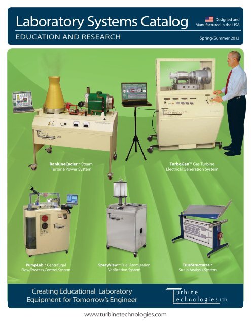
<strong>Laboratory</strong> <strong>Systems</strong> <strong>Catalog</strong><br />
EDUCATION AND RESEARCH<br />
Designed and<br />
Manufactured in the USA<br />
Spring/Summer 2013<br />
RankineCycler TM Steam<br />
<strong>Turbine</strong> Power System<br />
TurboGen TM Gas <strong>Turbine</strong><br />
Electrical Generation System<br />
PumpLab TM Centrifugal<br />
Flow/Process Control System<br />
SprayView TM Fuel Atomization<br />
Verification System<br />
TrueStructures TM<br />
Strain Analysis System<br />
Creating Educational <strong>Laboratory</strong><br />
Equipment for Tomorrow’s Engineer<br />
www.turbinetechnologies.com
25 Years In The Making<br />
For a quarter century, <strong>Turbine</strong> <strong>Technologies</strong>, Ltd. has quietly been designing and<br />
manufacturing some of the world’s finest and most exciting educational systems<br />
to help today’s sophisticated faculty train tomorrow’s successful engineer.<br />
IMAGINE THE POSSIBILITIES…<br />
Engineering students today have more choices than<br />
ever for their education, and the best tools can make a<br />
significant difference in a program’s success. Whether<br />
for curriculum, research or student recruitment; there’s<br />
never been a better time to elevate your program with<br />
quality lab equipment from <strong>Turbine</strong> <strong>Technologies</strong>.<br />
Perry and Todd would be delighted to answer any<br />
product or delivery questions you may have. Give us a<br />
call or send us an email. We’ve been providing the level<br />
of quality and service that the world’s best programs<br />
have come to expect – 25 years strong.<br />
Perry Kuznar, PE<br />
Product Application Engineer<br />
perry@turbinetechnologies.com<br />
715-924-4876 x 111<br />
Visit our website for more information<br />
www.turbinetechnologies.com<br />
Todd Gaines<br />
Product Application Specialist<br />
todd@turbinetechnolgies.com<br />
715-924-4876 x 112<br />
Stay informed via your favorite social media feed<br />
We post regular updates that include interesting engineering related topics like technical<br />
papers, videos, unique manufacturing photos and stories of real-world engineering challenges!<br />
Facebook: facebook.com/turbinetechnologies<br />
Twitter: twitter.com/#!/<strong>Turbine</strong>TechLabs<br />
2 TURBINE TECHNOLOGIES LABORATORY SYSTEMS CATALOG | 2013
What Do End-Users Have To Say About <strong>Turbine</strong> <strong>Technologies</strong>, Ltd.?<br />
“ My experience in doing business with TTL for the benefit of Penn State students is<br />
indeed rewarding. After ten years of operation, the thrust calibration of our SR-30<br />
(gas turbine engine) remains unchanged, and experiments with the PumpLab firmly<br />
establish the principles of dimensional analysis in our turbo-machinery course;<br />
Not only the quality of the labs, but also the customer support and goodwill of TTL<br />
personnel have enabled countless enhanced learning experiences at PSU.”<br />
Dr. Horacio Perez-Blanco<br />
Professor of Mechanical Engineering • The Pennsylvania State University<br />
“The University of Bahrain purchased two products from <strong>Turbine</strong> <strong>Technologies</strong>, LTD,<br />
namely; the Rankine Cycler and the Centrifugal Pump unit for the Fluid Mechanics<br />
<strong>Laboratory</strong>. These units enhanced students awareness of real life understanding<br />
of steam power generation and turbo machinery working principles due to near<br />
production-scale features, including updated technology built into these units. Over<br />
years of use, the two products have shown high reliability and maintainability. In<br />
addition, after sales technical and consultative support from the factory was excellent”.<br />
Dr. M. Bassam Nabhan<br />
Fluid Mechanics <strong>Laboratory</strong> Coordinator • Department of Mechanical Engineering<br />
University of Bahrain<br />
Wind <strong>Turbine</strong><br />
Power System<br />
Steam <strong>Turbine</strong><br />
Power System<br />
Centrifugal<br />
Flow System<br />
Air Foil<br />
Structures Lab<br />
Product Index<br />
“The RankineCycler is the best tool on the market for laboratory teaching of<br />
thermodynamic principles and power generation, and it comes with the lowest price<br />
tag. In fact, as far as I can tell, it is the only available educational equipment of its kind.”<br />
Dr. Andrew Gerhart<br />
Associate Professor of Mechanical Engineering • Lawrence Technological University<br />
WindLab <strong>Turbine</strong> Power System................................................4<br />
RankineCycler Steam <strong>Turbine</strong> Power System.............................8<br />
PumpLab Centrifugal Flow System.........................................10<br />
TrueStructures Air Foil Structures Lab.....................................16<br />
MiniLab Gas <strong>Turbine</strong> Power System........................................18<br />
Designed and<br />
Manufactured in the USA<br />
TurboGen Gas <strong>Turbine</strong> Electrical Generation System...............22<br />
OneTouch Gas <strong>Turbine</strong> Auto Start System................................24<br />
HushKit Gas <strong>Turbine</strong> Sound Suppressor System.......................26<br />
SprayView Fuel Automization Verification System...................28<br />
SR-30 Cutaway Turbojet Engine..............................................30<br />
Specifications and pricings are subject to change without notice.<br />
Creating Educational <strong>Laboratory</strong> Equipment for Tomorrow’s Engineer | www.turbinetechnologies.com 3<br />
Gas <strong>Turbine</strong><br />
Power System<br />
Gas <strong>Turbine</strong><br />
Electrical System<br />
Fuel Atomization<br />
Verification<br />
Cutaway<br />
Turbojet Engine
Wind <strong>Turbine</strong><br />
Power System<br />
NEW!<br />
4 LABORATORY SYSTEMS CATALOG | 2013
Wind <strong>Turbine</strong><br />
Power System<br />
Creating Educational <strong>Laboratory</strong> Equipment for Tomorrow’s Engineer | www.turbinetechnologies.com<br />
5
Wind <strong>Turbine</strong><br />
Power System<br />
6 LABORATORY SYSTEMS CATALOG | 2013
Wind <strong>Turbine</strong><br />
Power System<br />
Creating Educational <strong>Laboratory</strong> Equipment for Tomorrow’s Engineer | www.turbinetechnologies.com<br />
7
Steam <strong>Turbine</strong><br />
Power System<br />
8 LABORATORY SYSTEMS CATALOG | 2013
Steam <strong>Turbine</strong><br />
Power System<br />
Creating Educational <strong>Laboratory</strong> Equipment for Tomorrow’s Engineer | www.turbinetechnologies.com<br />
9
PumpLab TM<br />
Centrifugal Flow System<br />
Centrifugal<br />
Flow System<br />
A fully self-contained<br />
fluid flow laboratory<br />
enabling a range of<br />
study from introductory<br />
fluid mechanics through<br />
advanced fluid<br />
machinery<br />
analysis.<br />
Product Summary<br />
• Mobile Test Set for the Complete Exploration of Flow and Fluid Machinery Fundamentals<br />
• Ideal for Both Academic Education and Industrial Training<br />
• Fully Instrumented for Flow, Head, Power and Efficiency Analysis<br />
• Clear Fluid Circuitry Reveals All Flow and Cavitation Phenomena<br />
• Integrated Digital Motor Controller Displays Pump RPM, Current and Torque Values<br />
• Complete with Quick Change Straight, Forward and Backward Curved Impellers<br />
• DigiDAQ TM Data Acquisition System Utilizing USB Technology<br />
• User Configurable Real Time Computer Data Display<br />
• Designed to Meet ABET Criterion 4 and 6 Objectives<br />
• Supplied with a Comprehensive Operator’s Manual, Checklists and Safety Instructions<br />
• Industry Leading Warranty with Unsurpassed End-User Support<br />
• Designed and Manufactured in the USA<br />
CREATING EDUCATIONAL LABORATORY EQUIPMENT FOR TOMORROW’S ENGINEER<br />
10 LABORATORY SYSTEMS CATALOG | 2013
PumpLab TM<br />
Centrifugal Flow System<br />
Description<br />
A self-contained fluid flow laboratory designed for introductory and advanced fluid mechanics study. Basic fluids concepts involving energy and<br />
mass conservation, internal flow, the Bernoulli principal and Reynolds number are readily studied. Experimental investigation into<br />
advanced topics relating momentum, the Euler equation and fluid machinery analysis are also possible. Purely technical subjects regarding<br />
pump operation, performance analysis, piping systems and seal technology are immediately demonstrated and explored. Maximizing the<br />
educational impact of textbook direct examples, the PumpLab TM is suitable for a wide range of academic settings. From secondary through<br />
university and technical universities, the relationship between the theoretical and practical is clearly illustrated through experimentation with the<br />
PumpLab TM .<br />
The universal centrifugal pump forms the core of the PumpLab TM Centrifugal Flow System. Used throughout industry, the centrifugal pump is an<br />
effective way to introduce both theoretical and practical fluid machinery concepts. Featuring the industry's only clear view pump housing, student<br />
understanding is maximized through direct observation of the various pump components. The pump housing, inlet, outlet, diffusion volute,<br />
impeller, shaft seals and drive coupling are all visible during system operation.<br />
Straight, forward and backward curved impellers are provided to fully illustrate the effects of pump geometry on head and volume flow rate<br />
relationships. The various impellers can be interchanged with minimal effort and virtually no system downtime. Unique to the PumpLab TM is the<br />
availability of custom manufactured impellers. Low cost blanks and custom finished impellers are available to meet the needs of engineering<br />
classes with student design and project requirements. Direct access to the impellers and the ability to create new designs aids in student<br />
understanding of velocity diagram analysis and provides a foundation for advanced turbomachinery study.<br />
Pump rotation is accomplished through a state of the art computerized vector drive. This programmable controller allows an infinite array of pump<br />
control schemes to be explored including variable-speed and constant torque operation. Considerably more versatile than a fixed speed motor,<br />
the variable-speed feature allows experimentation into high efficiency electronic fluid flow rate control. Concepts of power management, energy<br />
conservation and cost savings in the context of pumps and pumping systems can be examined with regard to real world needs and modern<br />
industry trends.<br />
Centrifugal<br />
Flow System<br />
Water enters the pump through an instrumented test section offering expandability and operator customization. Exit flow passes through a<br />
transparent flow rotometer providing qualitative and digital indication of flow speed. Both the inlet and exit sides of the pump are equipped with<br />
valving to vary system load and head as well as to effect and control cavitation onset and propagation. The included strobe light coupled with the<br />
clear view pump housing makes cavitation and boundry layer phenomena dramatically apparent. All flow originates and ends in the fluid supply<br />
tank. Once filled, this tank requires no outside plumbing to maintain operation. The size and proximity of the supply tank lends itself to additional<br />
experimentation involving fluid statics and buoyancy.<br />
All system components are pre-mounted on a rigid steel chassis equipped with rolling castors for portability and ease of storage. System piping<br />
is high-strength PVC or acrylic. The pump housing, rotometer and test section areas are computer numerically controlled finished machined and<br />
polished to minimize optical distortion. Metal surfaces are stainless steel, anodized or powder coated for durability and ease of maintenance.<br />
The water supply tank is integral to the unit and completely corrosion proof. All pump and piping system components are in plain view for instant<br />
identification, access and observation. Pump impellers and the provided support tools are securely stored and displayed in the integrated front<br />
cabinet. System controls are intuitive and conveniently<br />
located on the front panel. A keyed master switch is<br />
standard and provides secure control of system usage.<br />
A pump prime switch is used to conveniently operate<br />
the built in pump priming system. The motor control<br />
keypad and display allows direct access to all pump drive<br />
motor functions and indicates key motor variables.<br />
A USB connected digital data acquisition system is fully<br />
integrated and precalibrated. Industrial grade sensors<br />
measure system parameters for real time display on the<br />
provided computer. Data can be recorded for playback<br />
or follow on analysis. Data acquisition software is user<br />
configurable without programming.<br />
A comprehensive Operator's Manual details all aspects<br />
of system operation. Complete technical and service<br />
information allows students, educators and technicians<br />
to gain a thorough understanding of system design,<br />
operation and construction. Summary operating<br />
checklists allow rapid mastery of system operation.<br />
Safety instructions address all operating conditions.<br />
CREATING EDUCATIONAL LABORATORY EQUIPMENT FOR TOMORROW’S ENGINEER<br />
Creating Educational <strong>Laboratory</strong> Equipment for Tomorrow’s Engineer | www.turbinetechnologies.com<br />
11
PumpLab TM TM<br />
Centrifugal Flow Flow System System<br />
Experimental Experimental Opportunities Opportunities<br />
Numerous Numerous experimental experimental and research and research opportunities opportunities are available are available and readily and readily conducted conducted with the with PumpLab the PumpLab TM Centrifugal TM Centrifugal Flow Flow System. System. The The<br />
installed installed pressure pressure and flow and sensors flow sensors allow allow basic basic experimentation experimentation relating relating to typical to typical secondary secondary physics physics and undergraduate and undergraduate fluid dynamics fluid dynamics courses. courses.<br />
Immediate Immediate access access to the to three the three common common pump pump impeller impeller types types permits permits detailed detailed analysis analysis and experimental and experimental verification verification of energy, of energy, momentum momentum and and<br />
fluid fluid machinery machinery type type problems. problems. With With the advanced the advanced vector vector drive drive system, system, concepts concepts concerning concerning efficiency efficiency and power and power conservation conservation are easily are easily<br />
explored. explored. Visual Visual vaporization vaporization bubbles bubbles help help in the in understanding the understanding correlation and correlation of cavitation of cavitation phenomena. phenomena. Standard Standard courses courses in engineering<br />
engineering<br />
thermodynamics thermodynamics and fluid and fluid mechanics mechanics benefit benefit from from textbook textbook direct direct examples examples conducted conducted and measured and measured in real in time. real time. The limitations The limitations of theoretical of theoretical<br />
models models and the and variability the variability of experimental of experimental technique technique can be can experienced be experienced first hand. first hand. In addition In addition to academics, to academics, the PumpLab the PumpLab TM is ideally TM is ideally suited suited for for<br />
general general pump pump and flow and flow system system familiarization familiarization as well as as well advanced as advanced practical practical studies studies for the for technical the technical and vocational and vocational student. student.<br />
Illustrative Illustrative examples examples of typical of typical pump pump performance performance computations computations and exercises and exercises ~ ~<br />
Centrifugal<br />
Flow System<br />
With With measured measured values values of pump of pump inlet and inlet outlet and outlet pressure, pressure, flow rate, flow rate, flow areas, flow areas, impeller impeller geometry, geometry, motor motor torque, torque, RPM, RPM, current current draw draw and and<br />
power, power, determine: determine:<br />
• Turbomachinery • Turbomachinery Analysis Analysis - angular - angular momentum, momentum, Euler Euler Turbomachine Turbomachine equation, equation, velocity velocity polygon polygon analysis analysis and idealized and idealized<br />
centrifugal centrifugal pump pump performance performance prediction prediction<br />
• Pump • Pump Characteristics Characteristics - actual - actual head, head, power power required required and efficiency and efficiency at various at various flow rates flow rates / pump / pump speeds speeds<br />
• Dimensional • Dimensional Analysis Analysis and Specific and Specific Speeds Speeds - determination - determination of coefficients of coefficients for pump for pump selection, selection, modeling modeling and scaling and scaling problems problems<br />
• Similarity • Similarity and Affinity and Affinity Analysis Analysis - design - design extrapolation extrapolation and performance and performance prediction prediction from from measured measured data data<br />
• Cavitation • Cavitation Analysis Analysis - quantifying - quantifying various various head head values values to predict, to predict, verify verify and measure and measure parameters parameters associated associated with the with the<br />
onset onset and propagation and propagation of cavitation of cavitation phenomena phenomena<br />
• Pump • Pump System System Analysis Analysis - performance - performance analysis analysis at various at various simulated simulated system system heads heads for determination for determination of pump of pump and system and system<br />
operating operating points points<br />
• Energy • Energy Conservation Conservation - varying - varying pump pump speed speed and system and system operating operating points points to achieve to achieve cost savings cost savings<br />
CREATING EDUCATIONAL LABORATORY EQUIPMENT FOR FOR TOMORROW’S ENGINEER ENGINEER<br />
12 LABORATORY SYSTEMS CATALOG | 2013
PumpLab TM<br />
Centrifugal Flow System<br />
Details<br />
Dimensions<br />
PumpLab TM :<br />
As Shipped:<br />
Weight<br />
PumpLab TM :<br />
As Shipped:<br />
71 x 48 x 29 inches (180 x 122 x 74 cm)<br />
81 x 55 x 33 inches (206 x 140 x 84 cm)<br />
455 lbs (206 kg)<br />
535 lbs (243 kg)<br />
Instrumentation<br />
Digital: High Speed Data Acquisition System<br />
Data Acquisition Software with Configurable Data Output<br />
Windows XP Computer for On-Screen Data Display<br />
Single Cable DigiDAQ TM USB to PC Connection<br />
20 Analog IN ~ 16 Digital IN/OUT ~ 4 Frequency/Pulse IN<br />
Sensors (Preinstalled and Calibrated)<br />
• Pump Inlet Pressure<br />
• Pump Exit Pressure<br />
• Flow Rate<br />
• Pump Torque<br />
• Pump RPM<br />
Provided Operational Accessories<br />
Three Impellers<br />
Straight Impeller ~ ß IN<br />
90˚ - ß OUT<br />
90˚<br />
Forward-Curved Impeller ~ ß IN<br />
90˚ - ß OUT<br />
115˚<br />
Backward-Curved Impeller ~ ß IN<br />
60˚ - ß OUT<br />
20˚ (with splitter vanes)<br />
Impeller Diameter, Outer 6.500” (16.51 cm) Inner 2.225” (5.65 cm)<br />
Impeller Blade Height, Outer 0.135” (0.34 cm) Inner 0.312” (0.79 cm)<br />
Stroboscope ~ adjustable from 0 to 3000 fps<br />
Impeller Change Tool<br />
Prime/ Drain T-Handle<br />
Operating Conditions / Limitations<br />
Main Pump and Supply Tank<br />
Maximum Flow Rate:<br />
Maximum Head:<br />
Tank Capacity:<br />
40 GPM (151 lpm)<br />
40 ft (12 mtrs)<br />
20 Gallons (76 ltrs)<br />
Main Pump Motor<br />
Maximum RPM 1725<br />
Shaft Power<br />
3.0 HP (2.2 kW)<br />
Current<br />
8.2 Amps<br />
Frame Style<br />
JM<br />
Auxiliary Prime / Drain Pump<br />
Maximum Flow Rate:<br />
Operating Requirements<br />
Typical <strong>Laboratory</strong> or Classroom Setting Power:<br />
220V single-phase 60Hz<br />
5 GPM (19 lpm)<br />
Purchase Specifications<br />
• A self-contained, mobile centrifugal flow<br />
system designed for engineering education.<br />
• Consisting of a centrifugal pump, computer<br />
controlled motor, flow rotometer, instrumented<br />
test section, pump inlet and exit valving,<br />
cavitation viewing stroboscope and integrated<br />
reservoir supply tank requiring no external<br />
water source.<br />
• Drive motor to be infinitely adjustable via<br />
computer controller with ability to regulate<br />
pump speed through torque, current or RPM<br />
measurement.<br />
• Transparent pump housing to reveal inlet,<br />
outlet, diffusion volute, impeller, shaft seals<br />
and drive coupling during system operation.<br />
• All flow circuit components to be transparent<br />
and mounted in clear view of operator.<br />
• Supplied with straight, forward and backward<br />
curved impellers and necessary tools to<br />
rapidly remove and replace.<br />
• Manufacture to make available blank and<br />
machined impellers at additional cost.<br />
• To be supplied with a USB based digital data<br />
acquisition system complete with computer<br />
and user configurable data acquisition<br />
software capable of measuring and recording<br />
analog, digital and frequency signals.<br />
• Equipped with calibrated transducers capable<br />
of measuring pump inlet and exit pressure,<br />
system flow rate, motor torque and RPM.<br />
• All metal surfaces to be stainless steel,<br />
anodized or powder coated to promote<br />
durability and wear resistance.<br />
• Provided with a comprehensive Operator’s<br />
Manual with design, operation and construction<br />
information.<br />
• Provided with summary operating checklists<br />
for all operating conditions.<br />
• Provided with safety instructions to address<br />
all operating conditions.<br />
• To be covered by a free two year warranty.<br />
Centrifugal<br />
Flow System<br />
CREATING EDUCATIONAL LABORATORY EQUIPMENT FOR TOMORROW’S ENGINEER<br />
<strong>Turbine</strong> <strong>Technologies</strong> Ltd. 410 Phillips St. Chetek, WI U.S.A • Ph: 715-924-4876 Fax: 715-924-2436 www.turbinetechnologies.com info@turbinetechnologies.com v19.3 © 2004<br />
Creating Educational <strong>Laboratory</strong> Equipment for Tomorrow’s Engineer | www.turbinetechnologies.com<br />
13
PumpLab<br />
Programmable Process Control<br />
New Feature!<br />
An integrated programmable controller<br />
with system pressure and flow feedback<br />
loops, along with PID gain application,<br />
can now be applied to a wide variety of<br />
fluid process flow control scenarios.<br />
Centrifugal<br />
Flow System<br />
Product Summary<br />
• Integrated Variable Frequency Drive with Programmable Control Keypad<br />
• USB Computer DAQ Screen with Active System Controls/Programming Functions<br />
• Integrated Pressure and Flow Control Feedback Loops<br />
• Integrated Process Set Points<br />
• Integrated Proportional, Integral and Derivative (PID) Gain Settings<br />
• Real Time Data Plot Display and Run-Time Data Recording<br />
• Included Sample Lab Procedure<br />
CREATING EDUCATIONAL LABORATORY EQUIPMENT FOR TOMORROW’S ENGINEER<br />
14 LABORATORY SYSTEMS CATALOG | 2013
PumpLab<br />
Programmable Process Control<br />
Description<br />
Centrifugal pumps are used extensively in industry to direct the flow of fluids for<br />
countless process requirements. Controlling the flow process is typically handled<br />
by a programmable Variable Frequency Drive (VFD). VFDs can be programmed to<br />
vary the control speed of the pump motor to allow the pump to meet the system<br />
fluid flow/pressure requirements. They can also be part of a large control scheme<br />
where many pumps are controlled and scheduled automatically to produce a<br />
desired result.<br />
Feedback loops are typically used in Programmable Logic Control (PLC) to provide<br />
information to the VFD regarding adjustments that need to be made to the<br />
pump ramp-up speed, operating speed, and ramp-down speed. The operational<br />
performace programming driven by Feedback Loops is fine-tuned through the<br />
application of gain.<br />
The PumpLab Process Control System features a programmable VFD that can be<br />
used to develop control scenarios for your pump. It also features dedicated<br />
feedback loops from pressure and flow transducers, which allow programming of<br />
specific process control scenarios. Proportional, Integral and Derivative (PID) gain<br />
capabilities are also integrated for tuning control response.<br />
An included sample lab procedure offers programmable process control scenario<br />
exercises to quickly familiarize the operator with this aspect of the PumpLab.<br />
The sample lab procedure is actually all-encompassing; it starts with PumpLab<br />
in the Pump Mode and teaches operators how to develop centrifugal pumping<br />
performance curves, using the supplied pump impeller profiles. This pump performance<br />
information can then be applied to countless fluid process control scenarios<br />
that can be derived and tested in PumpLab Process Control Mode.<br />
Process development and control are disciplines many practicing engineers<br />
become involved with. Having a good foundation of pumping and process control<br />
education, along with hands-on training, will be extremely valuable for designing/<br />
expanding effective pumping process systems that get results.<br />
Program Variable Frequency Drive via<br />
keypad or interactive software<br />
Experimental Opportunities<br />
Programmable Process Control is a<br />
significant added feature to the original<br />
PumpLab Centrifugal Flow Educational<br />
System. It enables students to take the<br />
centrifugal pump education derived from<br />
using the system in pump mode and apply<br />
it to fluid process control scenarios. This<br />
whole process becomes very valuable in<br />
managing and optimizing fluid processing.<br />
Since pumping is one of the major energy<br />
consumers, it is important to understand<br />
pumping and process control to optimize<br />
the results for a given amount of electrical<br />
energy consumption.<br />
•<br />
•<br />
•<br />
•<br />
Define process parameters.<br />
Develop feedback loop protocol.<br />
Fine-tune system response with gain.<br />
Utilize developed pump curves for process<br />
performance requirements.<br />
Develop custom impeller profiles to meet<br />
specific process requirements.<br />
•<br />
Centrifugal<br />
Flow System<br />
View real-time gain response to user-entered flow & pressure set points<br />
Purchase Specifications<br />
• LabVIEW interactive process control virtual<br />
instrument panel with real time sensor performance<br />
monitoring.<br />
• Baldor H2 industrial programmable Variable<br />
Frequency Drive (VFD).<br />
• Built-in process control programmable<br />
software.<br />
• Integrated data acquisition system.<br />
• Integrated Process Control Logic circuit.<br />
• Built-in pressure and flow feedback circuits.<br />
• System fully assembled, tested and ready to<br />
operate.<br />
• Detailed sample lab procedure included.<br />
CREATING EDUCATIONAL LABORATORY EQUIPMENT FOR TOMORROW’S ENGINEER<br />
<strong>Turbine</strong> <strong>Technologies</strong> Ltd. 410 Phillips St. Chetek, WI U.S.A • Ph: 715-924-4876 Fax: 715-924-2436 www.turbinetechnologies.com info@turbinetechnologies.com v9.8 © 2010<br />
Creating Educational <strong>Laboratory</strong> Equipment for Tomorrow’s Engineer | www.turbinetechnologies.com<br />
15
TrueStructures TM<br />
Airfoil Structures Lab<br />
A fully integrated structures<br />
laboratory utilizing actual<br />
aerospace components<br />
for a real - world<br />
understanding<br />
of structural<br />
behavior.<br />
Air Foil<br />
Structures Lab<br />
Product Summary<br />
• Compact Structures <strong>Laboratory</strong> Employing Actual Aerospace Components<br />
• Interchangeable Test Specimens Include Beam, Tube and Wing Section<br />
• Infinitely Variable Point Loading System to Apply Bending and Torsional Moments<br />
• Integrated Load Cell Provides Direct Indication of Actual Applied Load<br />
• Array of Preinstalled Strain Gauges to Measure Skin, Web and Beam Stresses<br />
• Strain Bridge Controller displays Strain Gauge Voltages and Applied Load<br />
• Software Tool Converts Measured Voltages to Engineering Strains<br />
• Visual Scales Provide Quick Indication of Test Specimen Deflection while Under Load<br />
• Extensive Sample Lab with Aero, Mechanical and Civil Engineering Applications<br />
• Designed to Meet ABET Criterion 4 and 6 Objectives<br />
• Industry Leading Warranty with Unsurpassed End-User Support<br />
• Designed and Manufactured in the USA<br />
CREATING EDUCATIONAL LABORATORY EQUIPMENT FOR TOMORROW’S ENGINEER<br />
16 LABORATORY SYSTEMS CATALOG | 2013
TrueStructures TM<br />
Airfoil Structures Lab<br />
Description<br />
TrueStructures is a complete structural analysis laboratory. Simple and complex bending,<br />
shear, and torsion are progressively demonstrated utilizing a beam, a tube and a<br />
complete aircraft airfoil structure.<br />
The TrueStructures Lab is ready for immediate usage upon uncrating. A powder coated<br />
main support frame is made from structural steel tubing and mounted on rolling castors<br />
for mobility. The entire lab is sized to fit through any standard interior door.<br />
A multi-lesson laboratory procedure is provided to illustrate common usage of the<br />
TrueStructures lab. Solid models are also included to show the internal wing structure.<br />
The solid models, laboratory procedures and strain calculation program are included on<br />
CD-ROM.<br />
Industry standard linear and rosette foil strain gauges are strategically mounted on all<br />
test components to allow gathering of structural strain data under various loading conditions.<br />
The custom manufactured Strain Bridge Controller manages strain gauge excitation<br />
and digitally displays the selected strain voltage. Each individual strain gauge is<br />
switch-selectable. A simple software application allows easy conversion between measured<br />
strain voltages and actual engineering strain. A separate digital meter displays the<br />
applied load at all times. System load and selectable strain gauge voltages are available<br />
as outputs from the Strain Bridge Controller for reading by external data acquisition or<br />
other measurement systems.<br />
Basic structural analysis can be studied with the readily interchangeable simple beam<br />
and tube structures. Unlimited opportunities exist with typical structures problems as<br />
well as the real world issues associated with experiment design, fundamental transducer<br />
concepts (strain gauges) and measurement noise. Provided lab projects include strain<br />
gauge fundamentals, applied loads, component section and material properties, principal<br />
and combined stresses, beam and torsional loading, shear flow and displacement.<br />
The TrueStructures Lab features an actual aircraft horizontal stabilizer. This lifting surface<br />
is typical of that found on civil and military aircraft where stressed skin construction<br />
is used. This “wing” structure is made up of an all aluminum outer skin, two span wise<br />
webbed main spars and a set of chord-wise main and nose ribs. The entire assembly is<br />
fastened together using riveted construction.<br />
The wing’s main spar is affixed in aerospace fashion to a root fitting similar to a wingfuselage<br />
structural joint. A mechanical jackscrew mechanism applies an infinitely variable<br />
point load to the wing tip. The point load can be positioned to place the specimen in<br />
pure bending, pure torsion, or combination loading. A precision load cell is mounted at<br />
the loading point that allows a direct readout of the applied force. Multiple uni-axial and<br />
rosette strain gages are strategically mounted throughout the wing to measure the resulting<br />
strain values.<br />
A free, two year warranty is provided on the entire TrueStructures system.<br />
Details<br />
Instrumentation<br />
Strain Bridge Controller:<br />
Wheatstone Bridge configuration, 12-channels individually selectable<br />
Digital display of strain voltages<br />
350 Ohm dummy gauges ≈ 2.09 Gauge Factor<br />
Self contained 15-volt strain gauge exitation supply<br />
Applied Load Indication:<br />
0-100 lbs Button Type Load Cell<br />
Digital display of applied load in lbs or kg<br />
Analog Output<br />
Strain Gauge: 0-10V proportional to strain voltage, channel selectable<br />
Applied Load: 0-10V proportional to load cell output<br />
Dimensions<br />
TrueStructures TM : 65L x 36W x 33H inches (165 x 91 x 84 cm)<br />
As Shipped: 72L x 48W x 45H inches (183 x 122 x 114 cm)<br />
Weight TrueStructures TM : 250 lbs (113 kg) As Shipped: 325 lbs (147 kg)<br />
Experimental Opportunities<br />
• Fundamental problems associated with statics<br />
and strength of materials.<br />
• Basic structures concepts of bending, shear and<br />
torsion.<br />
• Advanced problems with shear flow, combined<br />
loads and fittings.<br />
• Material shapes, section properties and their<br />
effects on structural efficiency.<br />
• Problems with loading, deflection and the stress<br />
& strain relationship.<br />
• Usage of strain gauges and support equipment<br />
for experimental stress determination.<br />
• Aerospace, civil and mechanical structures<br />
analysis and testing.<br />
• Design of experiments and data acquisition<br />
technique.<br />
Purchase Specifications<br />
• A multi-use structures laboratory designed for<br />
engineering education.<br />
• Utilizes interchangeable structural shapes that<br />
can be loaded in bending, torsion or combinations<br />
thereof.<br />
• Aerospace test article to be of an actual aircraft-lifting<br />
surface.<br />
• Provided with multi-lesson laboratory procedures.<br />
• To Include solid models of all test sections.<br />
• Equipped with an infinitely variable, manually<br />
adjusted loading apparatus.<br />
• Loading mechanism to be equipped with a fail<br />
safe over load device.<br />
• Button type load cell installed at the point of<br />
load and connected to a digital display to indicate<br />
applied load/force in pounds or kilograms.<br />
• Steel tape scale adjacent to the test article for<br />
the observation of deflection under load.<br />
• All test articles to be instrumented with industry<br />
standard, foil-type strain gauges.<br />
• Supplied with a 12-channel Strain Bridge Controller<br />
that powers the strain gauge circuit, is<br />
switch selectable between strain gauges and<br />
connected to a digital display to indicate selected<br />
strain gauge voltage.<br />
• Designed with an “open architecture” that allows<br />
additional strain gauges on existing or user<br />
test articles.<br />
• Frame to be manufactured from structural steel<br />
and finish powder coated as appropriate.<br />
• Frame assembly equipped with lockable rolling<br />
castors.<br />
• To be covered by a free two year warranty.<br />
Air Foil<br />
Structures Lab<br />
CREATING EDUCATIONAL LABORATORY EQUIPMENT FOR TOMORROW’S ENGINEER<br />
Creating Educational <strong>Laboratory</strong> Equipment for Tomorrow’s Engineer | www.turbinetechnologies.com<br />
<strong>Turbine</strong> <strong>Technologies</strong> Ltd. 410 Phillips St. Chetek, WI U.S.A • Ph: 715-924-4876 Fax: 715-924-2436 www.turbinetechnologies.com info@turbinetechnologies.com v4.13 © 2007<br />
17
MiniLab TM<br />
Gas <strong>Turbine</strong> Power System<br />
A fully integrated jet propulsion<br />
laboratory ideally suited for<br />
both introductory and<br />
advanced study of<br />
thermodynamic<br />
and operating<br />
principles of<br />
gas turbine<br />
power plants.<br />
Gas <strong>Turbine</strong><br />
Power System<br />
Product Summary<br />
• Complete Educational Jet Propulsion Power System<br />
• Suitable for Secondary, University, Technical and Military Education and Training<br />
• Purpose Built Gas <strong>Turbine</strong> Engine Designed and Manufactured to Aerospace Standards<br />
• Integrated Test Cell ~ Requires No Facilities Modification<br />
• All Key Engine Stations Fully Instrumented for Temperature and Pressure Measurement<br />
• Most Stable and Reliable Operation of any Engine in Size and Thrust Class<br />
• Fully Instrumented Operator Control Panel Featuring OneTouch TM Automatic Start<br />
• DigiDAQ TM Data Acquisition System Utilizing USB Technology<br />
• User Configurable Real Time Computer Data Display<br />
• Designed to Meet ABET Criterion 4 and 6 Objectives<br />
• Supplied with a Comprehensive Operator’s Manual, Checklists and Safety Instructions<br />
• Industry Leading Warranty with Unsurpassed End-User Support<br />
• Designed and Manufactured in the USA<br />
CREATING EDUCATIONAL LABORATORY EQUIPMENT FOR TOMORROW’S ENGINEER<br />
18 LABORATORY SYSTEMS CATALOG | 2013
MiniLab TM<br />
Gas <strong>Turbine</strong> Power System<br />
Description<br />
A complete gas turbine power plant designed for engineering, technical and military education as well as advanced research and study. The core<br />
gas-generator is representative of all major gas turbine types and permits ready textbook direct analysis of air equivalent Brayton and Gas<br />
<strong>Turbine</strong> cycles. Students are able to apply fluids, thermodynamic, combustion and gas turbine theory to the operation of an actual engine.<br />
<strong>Laboratory</strong> experience gained with the MiniLab is directly applicable to aero and marine turbine propulsion and industrial gas turbine applications.<br />
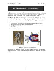
The SR-30 Turbo-Jet engine is designed and manufactured by <strong>Turbine</strong> <strong>Technologies</strong>, LTD specifically for the MiniLab Gas <strong>Turbine</strong> Power<br />
System. The compact engine features a centrifugal flow compressor, reverse flow annular combustor and an axial flow turbine stage. The SR-30<br />
follows the fundamental gas turbine cycle: Ambient air enters the engine through the bell shaped inlet. The air is then compressed, diffused and<br />
directed into the combustor can. Kerosene based fuel, introduced via six high-pressure atomization nozzles, is mixed with the compressed air<br />
and ignited. Heated combustion gas expands and accelerates through the vane guide ring causing the turbine to rotate. Useful work is extracted<br />
from this rotation as the turbine powers the compressor. The combustion gases are further accelerated through the thrust nozzle where the<br />
remaining heat energy is converted to kinetic energy in the form of jet thrust. The ejected gas returns to ambient atmospheric conditions thereby<br />
completing the thermodynamic cycle.<br />
For safety and performance reasons, no off-the-shelf, former military or surplus components are used in any portion of the engine. All components<br />
are manufactured in-house to exacting specifications. Electronic controlled vacuum investment casting insures void and impurity free components.<br />
Computer numerically controlled machine centers maximize finished part accuracy. Individual component materials are selected based upon<br />
desired mechanical properties, durability and longevity. Combustor components and the vane guide ring utilize Inconel® 718 alloy. The integral<br />
bladed disk turbine wheel is manufactured from CMR 247 Super Alloy. All material is fully traceable and verified to possess the desired properties<br />
specific to the application. The completed engine undergoes rigorous final operational testing and inspection. Purpose built from the start, the<br />
SR-30 requires no questionable modifications prior to integration into the MiniLab Gas <strong>Turbine</strong> Power System.<br />
The MiniLab cabinetry is composed of a rigid steel chassis mounted on rolling castors for portability and ease of storage, requiring no permanent<br />
facility modifications or additions. The SR-30 engine is securely mounted within the cabinet behind protective transparent polycarbonate shields<br />
affording the operator and observers clear, unimpeded viewing of the engine during operation. All engine accessories including fuel and oil<br />
pumps are located in the lower portion of the cabinet. No dedicated engine accessory drive is required, thereby eliminating the distraction of<br />
non-essential engine loading considerations in thermodynamic and performance analysis. Safe and reliable air starting provides for consistent<br />
and easy engine operation without the need for additional electric starters, complicated couplings, heavy cabling, high amperage current or<br />
auxiliary batteries. All fuel atomization is accomplished within the fuel control unit and adjacent nozzles. No gaseous fuels of any type are<br />
required for starting. A wide range of kerosene based or diesel blended fuels may be used without the need for any fuel preheating or conditioning.<br />
A single button initiates automatic engine start. System parameters are monitored during all phases of engine operation by an electronic<br />
engine control unit. Any out-of-limit condition results in the safe shutdown of the engine. Fuel and oil levels are monitored continuously<br />
thereby eliminating the potential for damaged pumps due to dry operation. Engine speed is fully controllable. A liquid crystal display panel<br />
alerts the operator to any system faults. Total run time and cycle counts are digitally recorded. A single button, prominently marked and readily<br />
located safely shuts the system down.<br />
Industrial grade sensors measure all key engine station parameters as<br />
well as overall system variables for real time display on the provided<br />
computer. Direct engine thrust is accurately measured through a<br />
pivoting bearing arrangement utilizing a calibrated load cell, eliminating<br />
problems inherent to linear bearings with critical alignment requirements.<br />
A USB connected digital data acquisition system is fully integrated and<br />
precalibrated. User configurable software allows the creation of custom<br />
data displays without the need for programming. Data can be recorded<br />
for playback or follow-on analysis. The full range of sensors allows<br />
calculations of fuel flow, thrust and pressure ratio to be compared<br />
directly to measured values.<br />
Design, technical and manufacturing information and specifications are<br />
available for specific teaching and research requirements. Actual engine<br />
components and system parts are optionally available for use as teaching<br />
and training aids. As the original engine manufacturer, complete spares<br />
availability is guaranteed. A free, two year warranty is provided on the<br />
entire MiniLab system including the SR-30 engine. Additional service<br />
and support is available as necessary. On site operator training is<br />
available at additional cost.<br />
A comprehensive Operator’s Manual details all aspects of system<br />
operation. Summary operating checklists allow rapid mastery of<br />
MiniLab Gas <strong>Turbine</strong> Power System operation. Safety instructions<br />
address all operating conditions.<br />
Gas <strong>Turbine</strong><br />
Power System<br />
CREATING EDUCATIONAL LABORATORY EQUIPMENT FOR TOMORROW’S ENGINEER<br />
Creating Educational <strong>Laboratory</strong> Equipment for Tomorrow’s Engineer | www.turbinetechnologies.com<br />
19
MiniLab TM TM<br />
Gas Gas <strong>Turbine</strong> Power System<br />
Experimental Opportunities<br />
Experimental and research opportunities include scientific, engineering, thermodynamic and and environmental investigations. With With a wide a wide array array of of<br />
sensors, experiments relating to secondary education physics and and chemistry through graduate level level fuels fuels and and combustion research research are readily are readily<br />
performed. Standard courses in in engineering thermodynamics and and fluid fluid mechanics benefit benefit from from textbook textbook direct direct examples examples conducted conducted and and<br />
measured in real time. The limitations of of theoretical models and and the the variability of of experimental technique technique can can be experienced be experienced first hand. first hand. In In<br />
addition to academics, the MiniLab is is ideally suited for for general gas gas turbine turbine familiarization and and jet engine jet engine operational operational training training for aviation for aviation and and<br />
military professionals.<br />
Illustrative examples of of Gas Gas <strong>Turbine</strong> computations ~ ~<br />
With<br />
With<br />
measured<br />
measured values<br />
values<br />
of<br />
of<br />
compressor<br />
compressor<br />
inlet<br />
inlet<br />
temperature<br />
temperature<br />
and<br />
and<br />
pressure,<br />
pressure,<br />
turbine<br />
turbine<br />
inlet<br />
inlet<br />
temperature<br />
temperature<br />
and<br />
and<br />
pressure,<br />
pressure,<br />
turbine<br />
turbine<br />
exit temperature<br />
exit temperature<br />
and<br />
and<br />
pressure,<br />
pressure, fuel<br />
fuel<br />
flow<br />
flow<br />
and<br />
and<br />
inlet<br />
inlet<br />
and<br />
and<br />
exit<br />
exit<br />
areas,<br />
areas,<br />
possible<br />
possible<br />
calculations<br />
calculations<br />
include:<br />
include:<br />
• Compressor Analysis - compressor pressure ratio, power required, rotational speed and compressor efficiency<br />
Compressor Analysis - compressor pressure ratio, power required, rotational speed and compressor efficiency<br />
• <strong>Turbine</strong> Analysis - work and power developed, expansion ratio and turbine efficiency<br />
<strong>Turbine</strong> Analysis - work and power developed, expansion ratio and turbine efficiency<br />
• Cycle / Brayton Type Analysis - mass flow rate, inlet and exit velocity, station temperature and pressures, combustion and thermal<br />
• efficiency, Cycle / Brayton specific Type fuel Analysis consumption - mass and flow power rate, / thrust inlet and developed exit velocity, station temperature and pressures, combustion and thermal<br />
efficiency, specific fuel consumption and power / thrust developed<br />
• Combustion Analysis - excess air and fuel-air ratio<br />
• Combustion Analysis - excess air and fuel-air ratio<br />
• General Analysis - diffuser and nozzle performance and efficiency<br />
• General Analysis - diffuser and nozzle performance and efficiency<br />
Gas <strong>Turbine</strong><br />
Power System<br />
Compressor Exit Temperature<br />
Compressor Exit Temperature<br />
Compressor Exit Pressure<br />
Compressor Exit Pressure<br />
<strong>Turbine</strong> Inlet Temperature<br />
<strong>Turbine</strong> Inlet Temperature<br />
<strong>Turbine</strong> Exit Temperature<br />
<strong>Turbine</strong> Exit Temperature<br />
<strong>Turbine</strong> Inlet Pressure<br />
<strong>Turbine</strong> Inlet Pressure<br />
RPM<br />
RPM<br />
Compressor Inlet Temperature<br />
Compressor Inlet Temperature<br />
Compressor Inlet Pitot Tube<br />
Compressor Inlet Pitot Tube<br />
Exhaust Gas Temperature<br />
<strong>Turbine</strong> Exit Pressure<br />
Exhaust <strong>Turbine</strong> Gas Exit Pressure<br />
Exhaust Gas Pressure<br />
Exhaust Gas Temperature<br />
CREATING EDUCATIONAL LABORATORY EQUIPMENT FOR TOMORROW’S ENGINEER<br />
20 LABORATORY SYSTEMS CATALOG | 2013<br />
CREATING EDUCATIONAL LABORATORY EQUIPMENT FOR TOMORROW’S ENGINEER
MiniLab TM<br />
Gas <strong>Turbine</strong> Power System<br />
Details<br />
Purchase Specifications<br />
Dimensions<br />
MiniLab:<br />
40 W x 42 D x 62 H inches (102 x 107 x 158 cm)<br />
As Shipped:<br />
48 W x 54 D x 70 H inches (122 x 137 x 178 cm)<br />
Weight<br />
MiniLab:<br />
460 lbs (208 kg)<br />
As Shipped:<br />
614 lbs (276 kg)<br />
Instrumentation<br />
Digital: High Speed Data Acquisition System<br />
Data Acquisition Software with Configurable Data Output<br />
Windows® XP Computer for On-Screen Data Display<br />
Single Cable DigiDAQ USB to PC Connection<br />
20 Analog IN - 16 Digital IN/OUT - 4 Frequency/Pulse IN<br />
Sensors (Preinstalled and Calibrated)<br />
• Compressor Inlet Temperature and Pressure (T1/P1)<br />
• Compressor Exit Temperature and Pressure (T02/P02)<br />
• <strong>Turbine</strong> Stage Inlet Temperature and Pressure (T03/P3)<br />
• <strong>Turbine</strong> Stage Exit Temperature and Pressure (T04/P04)<br />
• Thrust Nozzle Exit Temperature and Pressure (T05/P05)<br />
• Fuel Flow<br />
• Thrust<br />
• Engine Rotational Speed (RPM)<br />
Digital and Analog: As provided on the Operator Control Panel<br />
• Digital <strong>Turbine</strong> Inlet Temperature (TIT)<br />
• Digital Exhaust Gas Temperature (EGT)<br />
• Digital Engine Rotational Speed (RPM)<br />
• Analog Oil Pressure<br />
• Analog Engine Pressure<br />
• Analog Air Start Pressure<br />
Operator Panel Controls<br />
Master Switch, Keyed -<br />
Green Start Button, Push-<br />
Red Stop Button, Push-<br />
T-Handled Power Lever -<br />
Integral LCD Display -<br />
Secured control of equipment usage<br />
Initiates Engine Start, Multiple Functions<br />
Initiates Engine Shutdown, Multiple Functions<br />
Controls Engine RPM<br />
Real Time System Status<br />
Operating Conditions / Limitations<br />
Design Maximum Thrust: 40 lbf (178 N)<br />
Approved Fuels: Jet A, A-1, B; JP-4, 5, 8;<br />
Kerosene, Diesel, Fuel Oil #1 or #2<br />
Exhaust Gas Temperature: 1328˚ F (720˚ C)<br />
Mass Flow:<br />
Ignition System:<br />
1.1 lbs/s (0.5 kg/s)<br />
Air gap, high voltage capacitor discharge<br />
type hermetically sealed ignition coil and<br />
igniter plug<br />
Compressor Type:<br />
Single Stage Centrifugal (Radial Outflow)<br />
<strong>Turbine</strong> Type:<br />
Single Stage Axial Flow<br />
Design Maximum RPM: 87,000<br />
Engine Mount:<br />
Pivot bearing support allowing direct thrust<br />
to be obtained by a load cell<br />
Engine Compression Ratio: 3.4<br />
Engine Pressure Ratio: 30.0<br />
Specific Fuel Consumption: 1.2<br />
Approved Oils:<br />
Engine Diameter:<br />
Engine Length:<br />
Operating Requirements<br />
Typical <strong>Laboratory</strong> Setting<br />
Power:<br />
Air:<br />
MIL-PRF-23699F-STD<br />
6.8 inches (17 cm)<br />
10.8 inches (27 cm)<br />
120V single-phase 60Hz (220V upon request)<br />
Typically available 120PSI shop air<br />
• A complete gas-turbine power system to<br />
consist of an engine designed and<br />
manufactured for engineering education.<br />
• Engine must utilize a centrifugal flow compressor,<br />
reverse flow annular combustor and<br />
an axial flow turbine stage.<br />
• Engine to be of current manufacture and<br />
consisting of all new components.<br />
• All engine components either vacuum investment<br />
cast or precision CNC machined.<br />
• All high-heat components manufactured<br />
from 17-4 ph stainless steel, Inconel® 718<br />
or CMR 247 Super Alloy.<br />
• Traceable and verifiable material to be used<br />
throughout engine.<br />
• All elements comprising the system to be<br />
contained in a rigid steel chassis mounted<br />
on rolling castors.<br />
• All system metal surfaces to be stainless<br />
steel, anodized or powder coated to promote<br />
durability and wear resistance.<br />
• Complete system not to require any permanent<br />
facility modifications or additions.<br />
• Engine situated behind transparent protective<br />
shields allowing clear view during operation.<br />
• Operator capable of manual control throughout<br />
entire range of operation.<br />
• Operator panel to consist of digital TIT, EGT,<br />
and RPM indicators, analog oil pressure, engine<br />
pressure ratio, fuel pressure and air<br />
pressure gauges, keyed master, green start,<br />
red stop and T-handled power control lever.<br />
• System to be equipped with calibrated<br />
transducers and thermocouples capable of<br />
measuring compressor inlet, compressor exit,<br />
turbine stage inlet, turbine stage exit and<br />
thrust nozzle exit temperature and pressures,<br />
fuel flow, thrust and engine compressor /<br />
turbine rotational speed.<br />
• Engine thrust to be measured by a load cell<br />
permitting direct indication of thrust value.<br />
• To be supplied with a USB based digital data<br />
acquisition system complete with computer<br />
and user configurable data acquisition software<br />
capable of measuring and recording analog,<br />
digital and frequency signals.<br />
• Fully automatic engine start and operational<br />
health monitoring system provided with<br />
LCD status readout and cumulative runtime<br />
and cycle count.<br />
• Representative engine components and<br />
technical data optionally available for<br />
teaching use and training aids.<br />
• Manufacturer to guarantee spares availability<br />
and provide technical support services for<br />
core engine and power system.<br />
• Provided with a comprehensive Operator’s<br />
Manual.<br />
• Provided with summary operating checklist<br />
for all operating conditions.<br />
• Provided with safety instruction to address<br />
all operating conditions.<br />
• To be covered by a free two year warranty.<br />
Gas <strong>Turbine</strong><br />
Power System<br />
CREATING EDUCATIONAL LABORATORY EQUIPMENT FOR TOMORROW’S ENGINEER<br />
Creating Educational <strong>Laboratory</strong> Equipment for Tomorrow’s Engineer | www.turbinetechnologies.com<br />
<strong>Turbine</strong> <strong>Technologies</strong> Ltd. 410 Phillips St. Chetek, WI U.S.A • Ph: 715-924-4876 Fax: 715-924-2436 www.turbinetechnologies.com info@turbinetechnologies.com v1.7 © 2007<br />
21
TurboGen TM<br />
Gas <strong>Turbine</strong> Electrical Generation System<br />
A complete turboshaft engine<br />
genset illustrating the concepts<br />
of electrical power generation,<br />
thermodynamic cycles and<br />
mass and energy<br />
conservation.<br />
Gas <strong>Turbine</strong><br />
Electrical System<br />
Product Summary<br />
• Gas-<strong>Turbine</strong>-Driven Genset<br />
• Portable, Self-Contained and Ready to Operate<br />
• National Instruments TM DAQ System with Expandable LabVIEW TM Displays<br />
• Complete Thermodynamic Teaching Solution<br />
• Open-Ended Design to Meet ABET Criterion 3a,b,c,d,e,k and 4 Objectives<br />
• Nothing More to Add or Buy - Ready to Start Teaching upon Delivery<br />
• Supplied with a Comprehensive Operator’s Manual, Checklists and Safety Instructions<br />
• Industry Leading Warranty with Unsurpassed End-User Support<br />
• Designed and Manufactured in the USA<br />
CREATING EDUCATIONAL LABORATORY EQUIPMENT FOR TOMORROW’S ENGINEER<br />
22 LABORATORY SYSTEMS CATALOG | 2013
TurboGen TM<br />
Description<br />
Gas <strong>Turbine</strong> Electrical Generation System<br />
Experimental Opportunities<br />
A complete turboshaft engine genset instrumented for educational purposes.<br />
The compact jet engine gasifier core is representative of all major gas turbine types and<br />
entails an axial flow turbine stage, reverse flow annular combustor and radial flow<br />
compressor stage. This permits textbook direct analysis of the air equivalent Brayton<br />
Cycle. Students are able to apply fluids, thermodynamics, combustion and gas turbine<br />
theory to the operation of an actual engine.<br />
The electric power generation section features a thrust driven free power turbine<br />
directly coupled to a three phase liquid-cooled electric alternator. The generation circuit<br />
is base-loaded with an integrated fixed-value resistance module. An adjustable-rate<br />
excitation current controller allows wide-range alternator loading through the complete<br />
speed range of the generation system. The electrical power system can produce up to<br />
14.4 volts, with a maximum rated power output of 2.1 kW. A jet thrust driven exhaust fan<br />
effectively expels heat and exhaust from the engine/generator compartment.<br />
•<br />
•<br />
•<br />
•<br />
•<br />
•<br />
•<br />
•<br />
•<br />
•<br />
Energy relationships and the First Law of<br />
Thermodynamics.<br />
Cycle analysis and the Second Law of<br />
Thermodynamics.<br />
Control volume analysis.<br />
Entropy and enthalpy analysis.<br />
Isentropic analysis.<br />
Electric power generation analysis.<br />
Cycle and component efficiency studies.<br />
FEA & CFD analysis via available component<br />
CAD models.<br />
Airfoil velocity vector diagram construction.<br />
Experimental and data acquisition technique.<br />
A fully automated engine start and health monitoring system is also included, which<br />
entails a Liquid Crystal Display status readout with a built-in cycle/hour meter.<br />
Fifteen sensors report directly to an installed National Instruments DAQ platform,<br />
which entails customized LabVIEW displays (as depicted below). Data is configurable<br />
for output via numerous export options which include .txt and .csv file types.<br />
The gas turbine generation system is purpose designed for this application. All<br />
components of the engine and bulk of the generation system are manufactured and<br />
assembled at TTL. This true OEM approach results in an affordable, ready to operate,<br />
supportable educational solution.<br />
Data Acquisition<br />
& Gas Flow Path<br />
Screen Shot<br />
Details<br />
Dimensions TurboGen TM : 40 x 42 x 62 inches (102 x 107 x 158 cm)<br />
As Shipped: 48 x 54 x 70 inches (122 x 137 x 178 cm)<br />
Weight TurboGen TM : 460 lbs (208kg) As Shipped: 614 lbs (276kg)<br />
Instrumentation Data Acquisition System with Configurable Data Output<br />
Windows XP Laptop Computer for On-Screen USB Data Display<br />
Sensors<br />
• Compressor Inlet & Exit Temperature and Pressure<br />
• <strong>Turbine</strong> Inlet Temperature and Pressure<br />
• <strong>Turbine</strong> Exit / Power <strong>Turbine</strong> Inlet Temperature and Pressure<br />
• Power <strong>Turbine</strong> Exit Pressure and Temperature<br />
• Fuel Flow<br />
• Gasifier & Generator Rotational Speed (RPM)<br />
• Generator Current & Power<br />
Generator Limits Regulated Volts: 13.1 Volts Maximum Current: 194 Amps<br />
Maximum Power: 2541 Watts Maximum RPM: 5000<br />
Gasifier Limits Mass Flow: 1.1 lbs/s (0.5 kg/s) <strong>Turbine</strong> Inlet Temp: 1328˚F (720˚C)<br />
Engine Speed: 87,000 RPM<br />
Operating Approved Fuels: Jet A,A-1,B;JP-8;Kerosene, Diesel, Fuel Oil #1 or #2<br />
Requirements Approved Oil: MIL-PRF-23699F-STD<br />
Power: 120V single-phase 60Hz (220V 50Hz upon request)<br />
Air Pressure: 120 PSI (827 KPa)<br />
Purchase Specifications<br />
• A complete micro turbine genset to consist of<br />
an engine/generator combination designed<br />
and manufactured specifically for engineering<br />
education.<br />
• Engine must utilize an axial flow turbine stage,<br />
a reverse flow annular combustor, a free<br />
power turbine stage and a centrifugal compressor<br />
stage.<br />
• System to include a USB connected laptop<br />
computer interfaced with National Instruments<br />
hardware and customized<br />
LabVIEW VI displays.<br />
• System sensor package to entail 15 data<br />
reading points to include compressor inlet<br />
temperature and pressure, compressor stage<br />
exit temperature and pressure, turbine inlet<br />
temperature and pressure, power turbine<br />
inlet temperature and pressure, power turbine<br />
exit temperature and pressure, fuel flow,<br />
engine core RPM, power turbine RPM,<br />
generator current and power.<br />
• Engine to be of current manufacture and<br />
consisting of all new components.<br />
• Traceable and verifiable material to be used<br />
throughout engine.<br />
• All elements comprising the system to be<br />
contained in a rigid steel chassis mounted on<br />
rolling castors.<br />
• Complete system not to require permanent<br />
facility modification or additions.<br />
• Complete genset to be mounted behind<br />
transparent protective shields allowing clear<br />
view during operation.<br />
• Fully automatic engine start and operational<br />
health monitoring system provided with LCD<br />
status readout and cumulative run-time cycle<br />
count.<br />
• Representative engine components and<br />
technical data optionally available for<br />
teaching use and training aids.<br />
• Manufacturer to guarantee spares availability<br />
and provide technical support services for<br />
core engine and power system.<br />
• To be covered by a free two-year warranty.<br />
CREATING EDUCATIONAL LABORATORY EQUIPMENT FOR TOMORROW’S ENGINEER<br />
<strong>Turbine</strong> <strong>Technologies</strong> Ltd. 410 Phillips St. Chetek, WI U.S.A • Ph: 715-924-4876 Fax: 715-924-2436 www.turbinetechnologies.com info@turbinetechnologies.com v3.10 © 2010<br />
Creating Educational <strong>Laboratory</strong> Equipment for Specifications Tomorrow’s Subject Change Engineer Without Notice | www.turbinetechnologies.com 23<br />
Gas <strong>Turbine</strong><br />
Electrical System
OneTouch OneTouch TM<br />
TM<br />
Gas<br />
Gas<br />
<strong>Turbine</strong><br />
<strong>Turbine</strong><br />
Auto<br />
Auto<br />
Start<br />
Start<br />
System<br />
System<br />
An automatic<br />
An automatic<br />
electronic<br />
electronic<br />
engine<br />
engine<br />
control<br />
control<br />
unit<br />
unit<br />
designed<br />
designed<br />
for the<br />
for<br />
MiniLab<br />
the MiniLab<br />
Gas<br />
Gas<br />
<strong>Turbine</strong><br />
<strong>Turbine</strong><br />
Power<br />
Power<br />
System<br />
System<br />
& TurboGen<br />
& TurboGen<br />
Electrical<br />
Electrical<br />
Generation<br />
Generation<br />
System<br />
System<br />
that<br />
that<br />
ensures<br />
ensures<br />
ease<br />
ease<br />
of operation<br />
of operation<br />
&<br />
&<br />
engine<br />
engine<br />
longevity.<br />
longevity.<br />
TurboGen MiniLab<br />
Product<br />
Product<br />
Summary<br />
Summary<br />
• Autostart System Reflects Aero, Marine and Industrial <strong>Turbine</strong> Engine Practice<br />
• Autostart System Reflects Aero, Marine and Industrial <strong>Turbine</strong> Engine Practice<br />
• Fuel Introduction and Ignition Occurs at Optimal Engine RPM<br />
• Fuel Introduction and Ignition Occurs at Optimal Engine RPM<br />
• Electronic Monitoring Ensures Temperature and RPM Limitations Are Not Exceeded<br />
• Electronic Monitoring Ensures Temperature and RPM Limitations Are Not Exceeded<br />
• Operator Interface Displays N1%, TIT and EPR<br />
• Operator Interface Displays N1%, TIT and EPR<br />
• Total Engine Run-Time and Cycle Count Permanently Recorded<br />
• Total Engine Run-Time and Cycle Count Permanently Recorded<br />
• System Alerts Operator to Low Fuel and Low Oil Conditions<br />
• System Alerts Operator to Low Fuel and Low Oil Conditions<br />
• Exceeding Any Engine Limit Results in Immediate Engine Shutdown<br />
• Exceeding Any Engine Limit Results in Immediate Engine Shutdown<br />
• Engine is Manually Controllable Throughout Entire Operating Range<br />
• Engine is Manually Controllable Throughout Entire Operating Range<br />
• Software Upgradeable to Allow Incorporation of Periodic Updates<br />
• Software Upgradeable to Allow Incorporation of Periodic Updates<br />
• Automation Allows Operator to Focus on Educational or Research Activities<br />
• Automation Allows Operator to Focus on Educational or Research Activities<br />
• Industry Leading Warranty with Unsurpassed End-User Support<br />
• Industry Leading Warranty with Unsurpassed End-User Support<br />
• Designed and Manufactured in the USA<br />
• Designed and Manufactured in the USA<br />
CREATING EDUCATIONAL LABORATORY EQUIPMENT FOR TOMORROW’S ENGINEER<br />
CREATING EDUCATIONAL LABORATORY EQUIPMENT FOR TOMORROW’S ENGINEER<br />
24 LABORATORY SYSTEMS CATALOG | 2013
OneTouch TM<br />
Gas <strong>Turbine</strong> Auto Start System<br />
Description<br />
<strong>Turbine</strong> <strong>Technologies</strong> MiniLab Gas <strong>Turbine</strong> Power System and TurboGen Gas <strong>Turbine</strong><br />
Electrical Generation System feature a fully autonomous computer controlled start and engine<br />
monitoring system. Purpose designed and specifically built for the SR-30 Gas <strong>Turbine</strong><br />
Engine,the OneTouch system manages the engine start process and continuously monitors<br />
all subsequent engine operation. Should a critical engine parameter be exceeded,<br />
OneTouch immediately shuts the engine down and alerts the operator to the cause.<br />
OneTouch greatly simplifies engine operation and effectively frees the MiniLab operator<br />
to focus on instruction, demonstration and data gathering without compromising safety or<br />
engine health. With OneTouch, virtually anyone can operate the MiniLab or TurboGen<br />
with confidence and assurance that the safest and most efficient means are employed during<br />
the starting and operation of the engine.<br />
Two buttons and the traditional T-Handled Power Lever are all that is necessary to operate<br />
the MiniLab or TurboGen through the OneTouch system. A backlit LCD screen integral<br />
to the operator panel serves as the primary user interface. During normal operation, the LCD<br />
screen indicates all monitored engine parameters and provides a simple indication of system<br />
status. Should OneTouch command an engine shutdown, the cause for the shutdown will<br />
be displayed. Additional diagnostic and stored data retrieval functions are available through<br />
a combinatorial selection of the two buttons and power lever.<br />
Operation with OneTouch is both intuitive and straightforward. A keyed master switch limits<br />
system operation to those that are authorized to do so. With the keyed switch on, power is<br />
immediately applied to OneTouch. During system initialization, several screens are displayed<br />
that provide basic system information such as cumulative engine run-time and total<br />
engine start/stop cycles.<br />
Following initialization, OneTouch will display the normal operation screen and indicate<br />
that the engine is ready to start. Pressing the green START button commences the autostart<br />
sequence. Engine rotation begins through the introduction of starting air. Rotational speed is<br />
displayed as a percentage of the maximum engine RPM limit as indicated by the N1% value.<br />
As N1 increases, fuel is introduced at the appropriate time and ignited thereby starting the<br />
combustion process. The displayed <strong>Turbine</strong> Inlet Temperature (TIT) value will show an<br />
immediate temperature rise indicating positive combustion. As N1 continues to increase, the<br />
Engine Pressure Ratio (EPR) relating combustion pressure to ambient pressure will also<br />
increase. Starting air remains on until the engine achieves a stable idle rpm and the TIT has<br />
cooled to an acceptable level.<br />
The engine is now running and may be operated as desired. For reference purposes, an<br />
elapsed run-time counter displays the time since engine start. Stopping the engine is as easy<br />
as pressing the red STOP button. OneTouch continues monitoring the engine throughout<br />
the entire shutdown. Once N1 and TIT values are within safe start limits, OneTouch<br />
enables the engine for an immediate restart. Through OneTouch, the engine may be<br />
repeatedly started and stopped without any adverse affect to the engine or the lab system.<br />
During start and operation, should any critical engine value be exceeded or a problem found<br />
with any MiniLab or TurboGen system, OneTouch will command an engine shutdown<br />
and alert the operator to the problem. Faults are segregated between CAUTION and WARN-<br />
ING depending upon the severity of the problem and the operator intervention required to<br />
rectify the fault. A CAUTION is indicative of a minor problem that can be immediately fixed.<br />
Low fuel or oil levels are examples of CAUTIONs that are fixed simply by adding the appropriate<br />
fluid. A WARNING suggests the potential for a more serious problem that must be investigated<br />
before the engine can be run again. In the unlikely event a WARNING indication is<br />
experienced, the Operator’s Manual provides detailed instructions to assist with the WARN-<br />
ING condition prior to any subsequent operation.<br />
MiniLab<br />
TurboGen<br />
A software based system, OneTouch is easily upgraded and revised as changing<br />
requirements warrant. Hardware ports are available to facilitate interaction with the<br />
OneTouch system.<br />
CREATING EDUCATIONAL LABORATORY EQUIPMENT FOR TOMORROW’S ENGINEER<br />
Creating Educational <strong>Laboratory</strong> Equipment for Tomorrow’s Engineer | www.turbinetechnologies.com<br />
<strong>Turbine</strong> <strong>Technologies</strong> Ltd. 410 Phillips St. Chetek, WI U.S.A • Ph: 715-924-4876 Fax: 715-924-2436 www.turbinetechnologies.com info@turbinetechnologies.com v4.5 © 2005<br />
25
HushKit TM<br />
Gas <strong>Turbine</strong> Sound Suppressor System<br />
A gas turbine<br />
ducting system<br />
for the significant<br />
reduction of inlet<br />
and exit sound<br />
levels.<br />
TurboGen MiniLab<br />
Product Summary<br />
• Complete SR-30 TM Gas <strong>Turbine</strong> Sound Suppressor System<br />
• Typically Provides 84%~16dB(A) Intake and 75%~12dB(A) Exhaust Sound Reduction<br />
• Aircraft Style, Nacelle Shaped Fiberglass Intake Suppressor Housing<br />
• Stainless Steel Exhaust Suppressor Housing With Flame Plume Sight Window<br />
• Installation Does Not Interfere with Engine Operation or Sensor Measurement<br />
• Quick Installation Requires No MiniLab TM System Modifications<br />
• Compatible with All Typical User Installations<br />
• Requires No Operator Manipulation<br />
• Supplied with Comprehensive Installation and Usage Instructions<br />
• Industry Leading Warranty with Unsurpassed End-User Support<br />
• Designed and Manufactured in the USA<br />
CREATING EDUCATIONAL LABORATORY EQUIPMENT FOR TOMORROW’S ENGINEER<br />
26 LABORATORY SYSTEMS CATALOG | 2013
HushKit TM<br />
Gas <strong>Turbine</strong> Sound Suppressor System<br />
Description<br />
The HushKit TM Gas <strong>Turbine</strong> Sound Suppressor System is an optional silencer assembly<br />
available for installation in the MiniLab TM Gas <strong>Turbine</strong> Power System. Designed to reduce<br />
the sound level of the SR-30 TM Gas <strong>Turbine</strong> Engine, the HushKit TM is effective in both<br />
the academic and research setting and capable of retrofit to existing installations.<br />
The HushKit TM system is composed of individual intake and exhaust suppressor units.<br />
The aircraft style, nacelle shaped intake suppressor housing is designed to reduce<br />
acoustic energy associated with compressor intake flow. Molded from aerospace<br />
quality fiberglass, the intake suppressor mounts to the SR-30 TM Engine with a pneumatic<br />
friction seal system. This seal permits rapid installation and removal of the suppressor<br />
allowing full access to the engine inlet and compressor face for teaching<br />
and instructional purposes. The exhaust suppressor assembly is manufactured<br />
from stainless steel to maximize heat dissipation and durability. A positive pressure<br />
clamping system requires no modification of the existing MiniLab TM for installation. The<br />
suppressor exhaust ducting incorporates a glass sight window for flame plume visibility<br />
during starting operation. An acoustic expansion chamber on the end of the duct<br />
provides a convenient transition to facility specific exhaust ducting and integrates<br />
well with already existing installations. Neither the intake or exhaust suppressor assemblies<br />
interfere with engine operation.<br />
Comprehensive installation and usage instructions are provided. Once installed, no<br />
additional operator manipulation is required. A free, two-year warranty is provided.<br />
Details<br />
Dimensions<br />
Intake Suppressor:<br />
10 inches ø x 32 inches (25 x 81 cm)<br />
Exhaust Ducting:<br />
6 inches ø x 36 inches (15 x 91 cm)<br />
Exhaust Expansion Chamber: 10 inches ø x 10 inches (25 x 25 cm)<br />
Expansion Chamber is integral to, and mounts over Exhaust Ducting<br />
Weight<br />
Intake Suppressor:<br />
6 lbs (3 kg)<br />
Exhaust Suppressor: 15 lbs (7 kg)<br />
Operating Performance<br />
Decibel (dB) Levels Without and With Suppressor System Installed in MiniLab<br />
Engine Speed 50,000 RPM Engine Speed 84,000 RPM<br />
Position 3 feet 10 feet 25 feet 3 feet 10 feet 25 feet<br />
Controller Side 97/90 94/88 91/79 107/98 102/94 99/90<br />
Intake Side 120/103 112/91 103/86 124/113 121/106 108/96<br />
Exhaust Side 113/93 100/88 92/80 116/104 107/100 103/92<br />
Operating Conditions<br />
Typical <strong>Laboratory</strong> Setting<br />
Experimental Opportunities<br />
The HushKit TM is primarily offered as an operational<br />
accessory to the MiniLab TM Gas <strong>Turbine</strong> Power<br />
System. With a growing sensitivity to noise and<br />
a greater emphasis placed on environmentally<br />
friendly engineering, the MiniLab TM / HushKit TM<br />
combination provides a platform for the further<br />
study of gas turbine noise.<br />
• Gas turbine noise sources.<br />
• Isolation and measurement of engine core<br />
and jet exhaust noise.<br />
• Turbulence induced ambient air mixing in jet<br />
exhaust plume.<br />
• Acoustic energy absorption and dissipation<br />
techniques.<br />
• Engine performance degradation with various<br />
noise suppression methods.<br />
Purchase Specifications<br />
• A complete sound suppression system<br />
designed to reduce both engine core and jet<br />
noise.<br />
• Inlet suppressor manufactured from molded<br />
fiberglass.<br />
• Exhaust suppressor manufactured from<br />
stainless steel.<br />
• Exhaust suppressor duct to be equipped with<br />
flame plume viewing window.<br />
• Inlet and exhaust assemblies to be readily<br />
removable to allow access to engine.<br />
• Inlet and exhaust assemblies to be mounted<br />
in such a way as to not interfere with any<br />
operation of the engine.<br />
• To require no modifications of existing<br />
MiniLab TM unit.<br />
• Provided with a comprehensive installation<br />
and usage instructions.<br />
• To be covered by a free two-year warranty.<br />
MiniLab<br />
TurboGen<br />
CREATING EDUCATIONAL LABORATORY EQUIPMENT FOR TOMORROW’S ENGINEER<br />
<strong>Turbine</strong> <strong>Technologies</strong> Ltd. 410 Phillips St. Chetek, WI U.S.A • Ph: 715-924-4876 Fax: 715-924-2436 www.turbinetechnologies.com info@turbinetechnologies.com v4.20 © 2004<br />
Creating Educational <strong>Laboratory</strong> Equipment for Tomorrow’s Engineer | www.turbinetechnologies.com<br />
27
SprayView TM<br />
Fuel Atomization Verification System<br />
A complete jet engine fuel<br />
manifold spray system<br />
used to demonstrate &<br />
verify proper atomization<br />
of various fossil and<br />
renewable heavy fuels.<br />
Fuel Atomization<br />
Verification<br />
Product Summary<br />
• Portable <strong>Laboratory</strong>-Grade Fuel Atomization Verification System<br />
• Clear-View Spray Observation Chamber with Spray Verification Impingement Plates<br />
• Supplied with a Jet Engine Spray Manifold with Precision Variable Flow Control<br />
• Instrumented with Fuel Delivery Pressure and Digital Fuel Flow Meters<br />
• Requires No Tools, Facilities Modifications or Special Support to Operate<br />
• Integrated Fuel Spray Vacuum Capture / Drain System<br />
• Suitable for University, Technical and Military Education, Training and Research<br />
• Supplied with Comprehensive Instructions<br />
• Industry Leading Warranty with Unsurpassed End-User Support<br />
• Designed and Manufactured in the USA<br />
CREATING EDUCATIONAL LABORATORY EQUIPMENT FOR TOMORROW’S ENGINEER<br />
28 LABORATORY SYSTEMS CATALOG | 2013
SprayView TM<br />
Fuel Atomization Verification System<br />
Description<br />
SprayView is an optional fuel spray testing system for the SR-30 Gas <strong>Turbine</strong><br />
Engine manufactured by <strong>Turbine</strong> <strong>Technologies</strong>, Ltd. It has been designed with a built-in<br />
engine spray manifold to allow MiniLab operators the ability to test the atomization<br />
characteristics of fuels before they are actually burned in the engine. Proper atomization<br />
verification is especially important for testing of alternative fuel formulations such<br />
as bio-diesels. Improper spray patterns signify fuel formulations that are not compatible<br />
with the existing engine fuel injection system. Attempting to run an engine with these<br />
non-conforming fuel formulations could potentially damage it.<br />
The SprayView system also allows MiniLab operators to remove their actual<br />
SR-30 Engine Fuel Spray Manifold and test it for proper operation. Injector nozzles<br />
can be inspected for any build-up of contaminants and can be conveniently cleaned for<br />
continued reliable performance when reinstalled on the engine. Periodic checks in this<br />
manner, especially when testing experimental fuel formulations, can reduce the chances<br />
of injector clogging, essentially eliminating potential engine operating problems.<br />
SprayView features a clear view spray observation chamber allowing the operator to<br />
visually inspect the fuel spray pattern. Integrated impingement plates can be lined up<br />
under each spray nozzle to verify their spray integrity. The built-in fuel capture system<br />
pulls the injected fuel into a collection tank, which can be conveniently drained after the<br />
tests. An integrated spray throttling system allows the operator to vary the fuel spray to<br />
determine the optimum spray atomization “cloud” for a particular fuel. For students and<br />
researchers alike, the ability to actually see the fuel spray patterns, combined with<br />
concurrent readouts of system pressure and flow information provide a unique ability to<br />
verify fuel atomization integrity.<br />
SprayView is self-contained and requires only 110V power for operation (220 Volt<br />
upon request). The system arrives fully assembled, tested and ready to use.<br />
Comprehensive utilization instructions are provided as well as a free, two-year warranty.<br />
Experimental Opportunities<br />
SprayView is primarily offered as an<br />
accessory to the MiniLab Gas <strong>Turbine</strong> Power<br />
System. With the growing need to do more with<br />
existing equipment, the MiniLab Gas <strong>Turbine</strong><br />
Power System finds itself being used by<br />
undergraduate students working to gain an<br />
understanding of the Brayton Power Cycle as<br />
well as researchers testing alternative fuel<br />
formulations for performance and emissions<br />
results. The ability to verify fuel integrity and to<br />
check an existing SR-30 engine fuel manifold<br />
for potential fuel injector clogging contaminants<br />
are major considerations for using the<br />
SprayView.<br />
• Check spray pattern and Integrity of various<br />
heavy fuel formulations.<br />
• Verify proper operational integrity of in-service<br />
engine spray manifold.<br />
• Suitable for integrating various atomization<br />
sensors such as lasers for advanced research.<br />
Details<br />
Dimensions SprayView: 29” x 22” x 63”H (74 x 56 x 160 cm)<br />
As Shipped: 35” x 28” x 69”H (89 x 71 x 175 cm)<br />
Weight SprayView: 160 lbs (73kg)<br />
As Shipped: 220 lbs (100kg)<br />
Operators Panel<br />
Electrical<br />
Digital Fuel Flow Meter<br />
Analog Fuel Pressure Gauge<br />
Keyed Master Switch<br />
Test Chamber Vacuum Switch<br />
Fuel Pump Switch<br />
120 Volt (220 Volt upon request) 50 / 60 Hz 8 Amp<br />
Purchase Specifications<br />
• An atomization system for testing heavy<br />
fuels.<br />
• A see through spray observation chamber.<br />
• Unit to include integrated spray verification<br />
impingement plates.<br />
• Built-in fuel throttle.<br />
• Vacuum fuel collection system.<br />
• Stainless steel fuel tank.<br />
• Stainless steel cabinetry.<br />
• Included engine spray test manifold.<br />
• An electric fuel pump.<br />
• A mechanical fuel pressure gauge.<br />
• A digital fuel flow meter.<br />
• Keyed master power switch.<br />
• Built-in locking casters for easy portability.<br />
• Fully assembled and ready to operate.<br />
• Provided with a comprehensive Operator’s<br />
Manual.<br />
• To be covered by a free two year warranty.<br />
Fuel Atomization<br />
Verification<br />
CREATING EDUCATIONAL LABORATORY EQUIPMENT FOR TOMORROW’S ENGINEER<br />
Creating Educational <strong>Laboratory</strong> Equipment for Tomorrow’s Engineer | www.turbinetechnologies.com<br />
<strong>Turbine</strong> <strong>Technologies</strong> Ltd. 410 Phillips St. Chetek, WI U.S.A • Ph: 715-924-4876 Fax: 715-924-2436 www.turbinetechnologies.com info@turbinetechnologies.com v9.29 © 2009<br />
29
SR-30 TM Cutaway Turbojet Engine<br />
A full-scale turbojet<br />
engine manufactured<br />
to reveal the inner<br />
workings and<br />
engineering<br />
details of a<br />
gas turbine<br />
power plant.<br />
Cutaway<br />
Turbojet Engine<br />
Product Summary<br />
• Complete SR-30 TM Turbojet Engine Cutaway<br />
• Compressor and <strong>Turbine</strong> Stages Readily Viewable<br />
• Ball Bearing Mounted Rotating Assembly Permitting Full Rotation<br />
• Turbomachinery Components Reveal Actual Blade Geometries<br />
• Reverse Flow Annular Combustor Can Clearly Visible<br />
• Provided with Black Anodized Aluminum Mounting Stand<br />
• Complete with Custom Storage and Transportation Case<br />
• Supplied with a Comprehensive Teaching Narrative<br />
• Designed to Meet ABET Criterion 4 and 6 Objectives<br />
• Industry Leading Warranty with Unsurpassed End-User Support<br />
• Designed and Manufactured in the USA<br />
CREATING EDUCATIONAL LABORATORY EQUIPMENT FOR TOMORROW’S ENGINEER<br />
30 LABORATORY SYSTEMS CATALOG | 2013
SR-30 TM Cutaway Turbojet Engine<br />
Description<br />
The SR-30 TM Gas <strong>Turbine</strong> Engine is designed and manufactured by <strong>Turbine</strong> <strong>Technologies</strong>,<br />
LTD specifically for the MiniLab TM Gas <strong>Turbine</strong> Power System. The SR-30 TM Cutaway<br />
is a full scale example of the actual operating power plant with portions of selected<br />
components removed to reveal the inner workings of the engine.<br />
A pure turbojet, the SR-30 TM is representative of all straight jet engines in which combustion<br />
results in an expanding gas that is sufficiently capable of producing useful work and<br />
propulsive thrust. Consisting of a centrifugal compressor, annular combustor and axial<br />
flow turbine, the SR-30 TM engine is typical of the gas generator core found in turbofan,<br />
turboprop and turboshaft gas turbine engines used for aero and marine propulsion and<br />
industrial applications.<br />
Experimental Opportunities<br />
• Gas turbine fundamentals.<br />
• Mechanical operating principles.<br />
• Detailed flow path analysis and visualization.<br />
• Mass and volume flow calculations.<br />
• Construction of blade angle, flow and vector<br />
velocity diagrams.<br />
• Examination of typical jet engine<br />
manufacturing and construction techniques.<br />
Flow path analysis is the preferred method to introduce gas turbine operating principles.<br />
With the SR-30 TM Cutaway, the entire flow process from inlet to exit is traceable, matching<br />
the path the actual fluids take through an operating engine. Each major component<br />
can be investigated in turn with study given to how the individual parts contribute to the<br />
overall function of the engine. Showcasing the complex internal configuration of the basic<br />
turbojet, the SR-30 TM Cutaway facilitates the qualitative understanding of gas turbine<br />
fundamentals and establishes a foundation for more advanced study. The SR-30 TM<br />
Cutaway completes the MiniLab TM Gas <strong>Turbine</strong> Power System. It is equally effective as<br />
an independent teaching aid and will further the understanding of gas turbine engine<br />
operation in any context.<br />
Unlike other cutaways or display models, the SR-30 TM Cutaway is meant to be handled<br />
and used for demonstration purposes. Hands on manipulation of the rotating assembly<br />
and the ability to conduct tactile exploration of the flow path enhance the potential for<br />
learning. Supplied with a rugged, road style transportation case, the SR-30 TM Cutaway<br />
may be safely transported and securely stored. A free, two year warranty is provided on<br />
the SR-30 TM Cutaway engine.<br />
A comprehensive teaching narrative is provided. It utilizes the SR-30 TM Cutaway to illustrate<br />
gas turbine concepts and operation. Additional material relating to the manufacturing<br />
and assembly process is also included.<br />
Details<br />
Dimensions<br />
SR-30 TM Cutaway:<br />
Storage Case:<br />
Weight<br />
SR-30 TM Cutaway:<br />
Storage Case:<br />
Combined:<br />
14.5 x 11.0 x 8.0 inches (37 x 28 x 20 cm)<br />
18.0 x 14.0 x 12.0 inches (46 x 36 x 31 cm)<br />
10 lbs (5 kg)<br />
23 lbs (10 kg)<br />
33 lbs (15 kg)<br />
All Actual and Representative Components<br />
• Inlet Bell and Compressor Casing<br />
• Compressor Spinner / 2 Pole Generator for Engine RPM Sensing<br />
• Centrifugal Flow Compressor and Diffuser<br />
• Reverse Flow Annular Combustor with Laser Cut Air Flow Holes<br />
• Outer Combustor Mantle<br />
• Metal Spun Combustor Transition Liner<br />
• Nozzle / Vane Guide Ring<br />
• Bladed Axial Flow <strong>Turbine</strong> Disk with Main Engine Shaft<br />
• <strong>Turbine</strong> Containment Ring<br />
• Thrust Cone and Thrust Nozzle<br />
• Fuel Manifold, Fuel Nozzles, Fuel Control Unit and Engine Backplate<br />
• Compressor and <strong>Turbine</strong> Oil Seals and Main Bearings<br />
• Typical Air, Fuel and Oil Fittings with Internal Engine Fluid Galleyways<br />
Storage Case<br />
Air Transport Association Approved Delicate Equipment Case<br />
Fully Lined and Latchable for Safe, Secure Transportation<br />
CREATING EDUCATIONAL LABORATORY EQUIPMENT FOR TOMORROW’S ENGINEER<br />
Creating Educational <strong>Laboratory</strong> Equipment for Tomorrow’s Engineer | www.turbinetechnologies.com<br />
Purchase Specifications<br />
• A complete, full-scale turbojet engine with<br />
portions of selected components removed to<br />
reveal the inner workings of the engine.<br />
• Engine to utilize a centrifugal flow compressor,<br />
reverse annular flow combustor and an axial<br />
flow turbine stage.<br />
• Engine to be of current manufacture and<br />
consisting of all new components.<br />
• Engine sufficiently open and accessible to<br />
trace entire gas flow through all components.<br />
• Rotating assembly capable of full rotation as<br />
in operating engine.<br />
• Engine supplied with and displayable on black<br />
anodized aluminum mounting stand.<br />
• To be supplied with a latchable aluminum ATA<br />
approved travel and storage case.<br />
• Provided with a comprehensive teaching<br />
narrative.<br />
• To be covered by a free two year warranty.<br />
<strong>Turbine</strong> <strong>Technologies</strong> Ltd. 410 Phillips St. Chetek, WI U.S.A • Ph: 715-924-4876 Fax: 715-924-2436 www.turbinetechnologies.com info@turbinetechnologies.com v1.07 © 2008<br />
Specifications subject to change without notice.<br />
Cutaway<br />
Turbojet Engine<br />
31
410 Phillips Street, Chetek, WI 54728 USA<br />
715-924-4876 www.turbinetechnologies.com<br />
Our Growing Global Operator Family...<br />
Aalborg University<br />
American Univ-Cairo<br />
Army Missile Command<br />
Auburn University<br />
Aviation High School-NY<br />
Austin Community College<br />
Baylor University<br />
Ben Gurion University<br />
Binghamton University<br />
Bismarck State College<br />
Boston University<br />
Bradley University<br />
Brigham Young University<br />
Brno University<br />
Brunel University<br />
Buffalo State College<br />
Cairo University-Egypt<br />
California Maritime Academy<br />
California State Univ-Chico<br />
California State Univ-Fresno<br />
California State Univ-Fullerton<br />
California State Univ-L.A.<br />
California State Univ-Long Beach<br />
California State Univ-Northridge<br />
California State Univ-Pomona<br />
Carnegie Mellon University<br />
Central Connecticut State<br />
Central Maine Comm College<br />
Central Univ Tech-S. Africa<br />
CFU-Ankara, Turkey<br />
Cincinnati State University<br />
Ciudad University-Mexico<br />
Civil Aviation Training-Thailand<br />
Clarkson University<br />
Cleveland Community College<br />
Cleveland State University<br />
College of New Jersey<br />
Columbia University-New York<br />
Concordia University-Montreal<br />
Curtin University-Malaysia<br />
Dalhousie University-Halifax<br />
Daniel Webster College<br />
Delft Technical University<br />
Dogus University-Turkey<br />
Drexel University<br />
Duke University<br />
Eastern Visayas University<br />
Eastern Washington University<br />
Ecole Central de Nantes<br />
Ecole Centrale de Lyon<br />
Ecole National dAerotechnique<br />
Ecole Polytechnique Montreal<br />
Edwards Air Force Base<br />
Embry-Riddle Aero Univ-FL<br />
Embry-Riddle Aero Univ-AZ<br />
Erie Community College<br />
Fairleigh Dickenson University<br />
FH Pinkafeld-Austria<br />
FH Gieseen Griedberg<br />
Fairfield University<br />
Fed Univ Rio De Janeiro<br />
Florida Atlantic University<br />
Florida Institute of Tech<br />
Frostburg State University<br />
General Vortex Energy<br />
Georgia Tech<br />
Global Scientific S.A. de C.V.<br />
Gonzaga University<br />
Government of Israel<br />
Hampden Engineering<br />
Howard University<br />
Hydro Green Energy<br />
IAT, Pune, India<br />
Imperial College London<br />
Indian Inst Tech-Kharagpur<br />
Indian Inst of Space Sci & Tech<br />
Indian Inst Tech-Bombay<br />
Indian Inst Tech-Indore<br />
Indian Inst Tech-Kanpur<br />
Indian Inst Tech-Madras<br />
Indian Inst Tech -Ropar<br />
Indiana University-Purdue<br />
Inha University-Korea<br />
IA University of Puerto Rico<br />
James Cook University-AU<br />
John Brown University<br />
Kettering University<br />
King Fahd Univ-Saudi Arabia<br />
Korea Military Academy<br />
Lafayette College<br />
Lake Area Technical Institute<br />
Lakehead University<br />
Lakeland College<br />
Lancaster University<br />
Lassen Community College<br />
Lawrence Tech University<br />
Lehigh University<br />
Lemigas-Indonesia<br />
Loughborough University<br />
Louisiana State University<br />
Louisiana Tech - Ruston, LA<br />
Loyola Marymount University<br />
Luminant Academy-TX<br />
Maine Maritime Academy<br />
Manhattan Community College<br />
Mass Maritime Academy<br />
McNeese State University<br />
Metro State College of Denver<br />
Miami University-OH<br />
Mississippi Gulf Coast CC<br />
Mississippi State University<br />
Montana State University<br />
Montana Tech - Butte, MT<br />
MTSSR - Brunei<br />
Nanyang Tech University<br />
Ngee Ann Poly-Singapore<br />
NASA Marshall<br />
National Cheng Kung Univ<br />
National Inst Tech-Agartala<br />
National University of Ireland<br />
New Mexico Tech<br />
New York Institute of Tech<br />
Ngee Ann Polytechnic<br />
SVKM’s NMIMS (India)<br />
North Carolina A&T State Univ<br />
North Carolina State University<br />
Northumbria University-UK<br />
Norwegian Univ Sci & Tech<br />
Norwich University<br />
Nova Scotia Comm College<br />
Ohio Northern University<br />
Ohio State University<br />
Ohio University<br />
Oklahoma Christian University<br />
Oklahoma City Cmty College<br />
Oklahoma State Univ-Okmulgee<br />
Oklahoma State Univ-Stillwater<br />
Oklahoma State Univ-Tulsa<br />
Oregon Inst of Technology<br />
Oregon State University<br />
Penn State Harrisburg<br />
Perm State University-Moscow<br />
Penn State University<br />
PerriQuest Defense Research<br />
Petroleum Institute-Abu Dhabi<br />
Pohang University-Korea<br />
Pontifica Universidad-Chile<br />
Pontificia Universidad Catolica<br />
Princeton University<br />
Republic of Korea<br />
Queens University of Belfast<br />
Queensboro Comm College<br />
Rand Afrikaans University<br />
Reykjavik University-Iceland<br />
Rio de Janeiro Coppetec<br />
RMIT University Australia<br />
Rose-Hulman Institute of Tech<br />
Royal Military Acad-Brussels<br />
Royal Thai Air Force<br />
Ruhr-Universitat Bochum<br />
Ryerson University-Toronto<br />
Salavat State Energy Train Ctr<br />
San Diego State University<br />
San Jose State University<br />
Seoul National University<br />
Siham Bagaffar-Saudi Arabia<br />
Singapore Polytechnic<br />
Southern Alberta Inst Tech<br />
South Illinois Univ-Carbondale<br />
South Illinois Univ-Edwardsville<br />
Southern Methodist University<br />
Southern Polytechnic<br />
Southern University<br />
Stanford University<br />
SUNY Maritime College-NY<br />
Swansea University - UK<br />
Swinburne University Tech<br />
Technical University of Ostrava<br />
Temasek Polytechnic<br />
Tennessee Tech University<br />
Texas A & M - College Station<br />
Texas A & M - Corpus Christi<br />
Texas A & M Galveston<br />
Texas A&M – Kingsville<br />
Texas Christian University<br />
Texas Gulf Supply<br />
Texas Tech University<br />
TH Mittelhessen-Germany<br />
Tsinghua University-Beijing<br />
The Victoria College-TX<br />
Three Rivers Comm College<br />
Tshwane University of Tech<br />
Tuskegee University<br />
U.S. Air Force<br />
U.S. Air Force Academy<br />
U.S. Dept. of Energy<br />
U.S. Merchant Marine Academy<br />
U.S. Naval Academy<br />
Union Electric - St. Louis, MO<br />
Univ. del Salento - Lecce, Italy<br />
Univ. Nacional de la Plata<br />
Univ. Nat. de Mexico<br />
Univ. Nuevo Leon - Mexico<br />
Univ. of Nova Gorica-Slovenia<br />
Univ. of Windsor<br />
Univ. Technologi-MARA<br />
Universiti Teknologi Malaysia<br />
University of Adelaide<br />
University of Akron<br />
University of Alabama<br />
University of Alabama-Birmingham<br />
University of Alaska-Fairbanks<br />
Univ of Arkansas - Little Rock<br />
University of Auckland<br />
University of Bahrain<br />
University of Calgary<br />
University of California-Davis<br />
University of California-LA (UCLA)<br />
University of Cape Town<br />
University of Central Florida<br />
University of Cincinnati<br />
University of Connecticut<br />
University of Dayton<br />
University of Edinburgh<br />
University of Evansville<br />
University of Florida<br />
University of Hawaii Manoa<br />
University of Houston<br />
Univ of Illinois – Champaign<br />
University of Kansas<br />
University of Kentucky<br />
University of Liege - Belgium<br />
Univ of Louisiana at Lafayette<br />
University of Maine<br />
University of Manchester<br />
University of Manitoba<br />
University of Maryland<br />
University of Memphis<br />
Univ of Miami-Coral Gables<br />
University of Miami<br />
Univ of Minnesota-Duluth<br />
Univ of Minnesota-Twin Cities<br />
University of Nebraska-Lincoln<br />
University of Nevada - Reno<br />
Univ of Nevada Las Vegas<br />
University of Nevada-Reno<br />
University of New Hampshire<br />
University of New Haven<br />
University of New Mexico<br />
University of North Carolina<br />
University of North Dakota<br />
University of North Florida<br />
University of North Texas<br />
University of Notre Dame<br />
University of Oklahoma<br />
UOIT- Oshawa<br />
University of Ottawa - Ontario<br />
University of Pittsburgh<br />
University of Portland<br />
University of Puerto Rico<br />
University of Rhode Island<br />
University of San Diego<br />
Univ of Shanghai Sci & Tech<br />
University of South Alabama<br />
University of South Carolina<br />
University of Southern Maine<br />
Univ of Technology-Jamaica<br />
Univ of Tennessee-Knoxville<br />
University of Texas-El Paso<br />
Univ of Texas - San Antonio<br />
University of Texas Arlington<br />
University of Texas at El Paso<br />
University of the Republic<br />
University of Waterloo<br />
University of the West Indies<br />
University of Witwatersrand<br />
University of Toledo<br />
University of Umea - Sweden<br />
Univ of Utah-Salt Lake City<br />
University of Valladolid-Spain<br />
University of Victoria<br />
University of Waterloo-Ontario<br />
University of Western Australia<br />
University of Western Ontario<br />
Univ of Wisconsin-Platteville<br />
UW-Platteville-Menasha<br />
Univer Syst of New Hampshire<br />
Utah State University<br />
Vanderbilt University<br />
Vermont Technical College<br />
Villanova University<br />
Virginia Commonwealth Univ.<br />
Virginia Military Institute<br />
VSB Tech University of Ostrava<br />
Washington State Univ-Pullman<br />
Washington State University<br />
Webb Institute-New York<br />
Wentworth Inst of Technology<br />
Western New England College<br />
Wharton County Junior College<br />
Widener University<br />
Wilberforce University<br />
Wolf Creek Nuclear Op Corp<br />
Wright Patterson AFB<br />
Wright State University<br />
Yale University<br />
Yonsei University - Korea