Membrane Pre-treatment Using Plate Settlers - Ohiowater.org
Membrane Pre-treatment Using Plate Settlers - Ohiowater.org
Membrane Pre-treatment Using Plate Settlers - Ohiowater.org

Create successful ePaper yourself
Turn your PDF publications into a flip-book with our unique Google optimized e-Paper software.
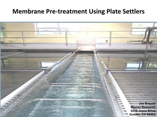
<strong>Membrane</strong> <strong>Pre</strong>-<strong>treatment</strong> <strong>Using</strong> <strong>Plate</strong> <strong>Settlers</strong><br />
Joe Brauch<br />
Meurer Research<br />
6270 Joyce Drive<br />
Golden, CO 80403
MEURER RESEARCH, INC.<br />
• Established in 1977 – Has over 35 years experience in<br />
designing clarifiers<br />
• Has been issued over 50 patents related to the<br />
sedimentation process<br />
• MRI has over 500 plate settler installations, more plates<br />
than anyone in the world.<br />
• MRI has manufactured over 4,000 sludge collectors,<br />
more than anyone in the world.
<strong>Plate</strong> <strong>Settlers</strong> in the <strong>Pre</strong>-Treatment Process<br />
•Effective pre-<strong>treatment</strong> will maximize the downstream<br />
processes, i.e. membranes and granular media filters<br />
•Sedimentation is the most popular method of pre<strong>treatment</strong><br />
•The sedimentation process is designed to remove the<br />
majority of settleable solids by gravitational settling
CONVENTIONAL SETTLING BASIN<br />
• Design parameters are that particles moving at velocity V H , starting at the<br />
water surface and falling at a velocity V S must reach the bottom, depth D,<br />
within the basin length L.<br />
• Influent elevation “d” must be used for calculations<br />
• Through calculations, Overflow Velocity (V O ) or Surface Overflow rate (SOR)<br />
can be determined<br />
L<br />
D<br />
d<br />
v S<br />
v H
MANY THINGS AFFECT THE PERFORMANCE OF A<br />
CONVENTIONAL BASIN<br />
• Flow rate changes<br />
• Local climate conditions<br />
o Air and water temperature changes – Water density<br />
o Wind velocity and direction<br />
• Events such as heavy rains<br />
• Inadequate sludge removal
CONVENTIONAL BASIN WITH SLUDGE<br />
ACCUMULATION<br />
•Reduces the size of the basin<br />
•Causes short circuiting
CONVENTIONAL BASIN AS SLUDGE BUILDS UP<br />
EVEN DISTRIBUTION<br />
INTO THE BASIN<br />
HIGHER VELOCITY DOWN<br />
THE BASIN<br />
FLOC CARRYOVER OCCURS<br />
SLUDGE BUILDS UP<br />
RESIDENCE TIME IS<br />
SHORTENED
EVOLUTION OF PLATE SETTLERS<br />
• Allen Hazen’s 1904 paper marked the beginning of<br />
modern sedimentation theory with the notion that a<br />
basin should be shallow therefore reducing the effects<br />
of hydraulic factors.<br />
• This was later advocated by Camp and the theory of the<br />
“tray settler” was born.
The problem was sludge removal from a horizontal tray.<br />
The answer was found by tilting the plates<br />
(trays) which resulted in the velocity vectors<br />
within the plate settler as we know it today<br />
3.5"<br />
Vg<br />
55 0
SETTLED SOLIDS EVACUATION<br />
Camp determined that settled solids accumulate into a mass.<br />
When the weight of the mass exceeds the shear resistance of the<br />
plate surface the mass slides down the 55 0 angle and off of the<br />
plate as a clump.<br />
The settled solids<br />
accumulate as a mass<br />
The weight of the mass<br />
exceeds the shear<br />
resistance and breaks<br />
away
<strong>Plate</strong><br />
Cartridges<br />
Feed Channels<br />
Flow Control<br />
Decks<br />
Stainless Steel Support Beam<br />
Sludge Collection
ADVANTAGES OF PLATE SETTLERS<br />
1. The settling distance is reduced by 98%, 3.5” compared to<br />
15’ in a conventional basin<br />
2. <strong>Plate</strong> settlers provide a “perfect environment” low<br />
velocities and minimized hydraulic effects<br />
3. Effects from wind, turbidity spikes and temperatures are<br />
minimized<br />
4. <strong>Plate</strong> settlers “overlap” therefore basin footprints are 20%<br />
as large as a conventional basin<br />
5. Effluent turbidities are
<strong>Plate</strong> settlers are set on 55 0 angle<br />
Falling particles see the<br />
“Projected Area” of each<br />
plate settler<br />
The loading rate is the rate of<br />
flow over the projected areas<br />
i.e. .3 gpm/ft 2<br />
The Projected Areas<br />
overlap<br />
The settling surface is<br />
much larger without plate<br />
settlers
Determine the horizontal projected area needed<br />
1. Choose the specific loading rate. For example a standard<br />
loading rate is 0.3 gpm/ft 2 of effective plate area at 90%<br />
efficiency.<br />
Calculations for 10 MGD (6950 GPM) example:<br />
Divide the flow in gpm by the loading rate:<br />
Flow = 6,950 = 23,166 ft 2 = projected area<br />
the Loading rate .3 GPM/ft 2<br />
Apply the efficiency<br />
SIZING CALCULATION EXAMPLE<br />
2. Divide the projected area by the efficiency – 90%<br />
Projected area = 23,166 ft 2<br />
efficiency .9<br />
= 25,740 ft 2 effective area
Convert the horizontal projected area to<br />
55 0 plate angle<br />
3. Divide the effective area by .574 (COS of 55 0 )<br />
to convert the surface area to 55 0<br />
25,740 ft 2 = 44,843 ft 2 of actual plate surface<br />
.574<br />
Convert the plate area to number of plate<br />
settlers<br />
4. Divide the actual plates surface area by the<br />
area of each plate (i.e. 45 ft 2 )<br />
44,843 ft 2 = 997 plates for 10 mgd<br />
45 ft 2
SITE INSTALLATION PROCESS<br />
Beams installed & <strong>Plate</strong>s are set into<br />
positioned<br />
<strong>Plate</strong> Packs are secured to the<br />
Beams<br />
Weirs are leveled and Installation<br />
completed<br />
Troughs are lowered in<br />
position
MIRAMAR WTP SAN DIEGO, CA – 220 MGD
BUNDAMBA AUSTRALIA – 40 MGD
LUGGAGE POINT, AUSTRALIA – 31 MGD
AUGUSTA, GA 20 MGD
ATLANTIC CITY, NJ - 20 MGD
WYOMING, MI – 90 MGD
JERSEY CITY, NJ – 90 MGD
GALLATIN, TN SUBMERGED PLATES – 20 MGD
SLUDGE REMOVAL
Design Criteria for Sludge Removal<br />
• Must remove settled solids over the entire floor<br />
• Provide low head sludge discharge such as:<br />
Low head directional orifice blocks<br />
• No flexible hoses or articulating pipes.<br />
• Must have the capability of higher removal rates in the<br />
front areas of the basin
GUIDE CURB<br />
TELESCOPING<br />
PIPE<br />
SUCTION<br />
HEADERS<br />
SLUDGE SCRAPERS
AUGUSTA, GA<br />
AUGUSTA, GA 4 UNITS
Cleaning cycle initiated: Valve opens - Drive starts
Cleaning cycle: Solids Removal
Cleaning cycle completed:<br />
Drive stops – 3 minute pipe flush – Valve closes
Return cycle:<br />
Drive starts - Orifices are back flushed
Return cycle completed:<br />
Drive stops
<strong>Membrane</strong> <strong>Pre</strong>-<strong>treatment</strong> <strong>Using</strong> <strong>Plate</strong> <strong>Settlers</strong><br />
THANK YOU FOR ATTENDING<br />
51 st Annual<br />
Water Workshop<br />
& Exhibition<br />
Joe Brauch<br />
Meurer Research<br />
6270 Joyce Drive<br />
Golden, CO 80403