Miata piggy back ECU installation & tuning - Flyin
Miata piggy back ECU installation & tuning - Flyin
Miata piggy back ECU installation & tuning - Flyin

You also want an ePaper? Increase the reach of your titles
YUMPU automatically turns print PDFs into web optimized ePapers that Google loves.
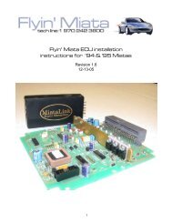
Section 3: O2 Signal Modifier and A/F Meter<br />
The O2 signal modifier is a small device that intercepts the factory O2 sensor signal before the<br />
factory <strong>ECU</strong>. It sends a conditioned signal to the <strong>ECU</strong> when the motor operates in boost to<br />
keep the factory <strong>ECU</strong> from “seeing” the additional fuel necessary under boost. An air/fuel (A/<br />
F) meter is also included to monitor the air fuel ratio when operating under boost.<br />
The metal panel under the steering column and the glove box should still be removed from<br />
the last section. The factory <strong>ECU</strong> is located under the dash board on the driver’s side of the<br />
car right above the clutch pedal. Standing on your head to work on the car will be necessary<br />
for this section. Use the supplied electrical connectors to connect the A/F meter and the O2<br />
signal modifier as follows. Refer to the diagrams on pages 10 &11 for the wire connections<br />
and the identification of the <strong>ECU</strong> terminals to be used.<br />
O2 Signal Modifier:<br />
1) Remove the three harness plugs from the<br />
<strong>ECU</strong> and cut off some of the electrical tape<br />
around the wires. This will allow you to separate<br />
them and access the individual wires<br />
needed for this operation.<br />
2) The first wire we are interested in is the blue<br />
wire in terminal A. This is the front O2 sensor<br />
signal wire. Cut the wire about two inches out<br />
from the <strong>ECU</strong> connector and strip ¼” of insulation<br />
off both ends.<br />
3) Crimp the blue wire on the O2 signal modifier<br />
to the <strong>ECU</strong> end of the cut blue wire in Terminal A using the supplied butt connector.<br />
4) Crimp the yellow wire from the O2 signal modifier to the O2 sensor end of the blue wire in<br />
terminal A using the supplied butt connector.<br />
5) Connect the red wire from the O2 signal modifier to the white/red wire in terminal B using<br />
the supplied quick splice connector.<br />
6) Connect the black wire from the O2 signal modifier to the black/red wire in terminal C using<br />
the supplied quick splice connector.<br />
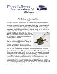
7) The pressure switch on the O2 signal modifier needs a pressure signal from the intake<br />
manifold. Use the “T” fitting to tap into the vacuum hose in to the signal line run through the<br />
fire wall for the boost gauge.<br />
8) If the Lambda Link A/F meter is not being used, jump to step 13.<br />
9