- Page 1 and 2: Power IT LV Active Filter PQFI Inst
- Page 3 and 4: 7.2. Checking the insulation of the
- Page 5 and 6: 9.9.11. Choice of a RS-232/RS-485 c
- Page 7 and 8: List of figures Figures Explanation
- Page 9 and 10: Figures Explanation Page Figure 7.4
- Page 11 and 12: List of tables Tables Explanation P
- Page 13 and 14: Tables Explanation Page Table 12.2.
- Page 15 and 16: 2. Safety Instructions These safety
- Page 17 and 18: 4. Upon reception 4.1. What this ch
- Page 19 and 20: 4.5. Storage PQFI packing is made f
- Page 21 and 22: Table 5.1. User connections for PQF
- Page 23 and 24: Top part 4 Middle part 2 3 1 Bottom
- Page 25 and 26: The current generator is physically
- Page 27 and 28: 5.5. The PQF-Manager user interface
- Page 29 and 30: WARNING: If a function is assigned
- Page 31: Table 5.8. Default set-up for the d
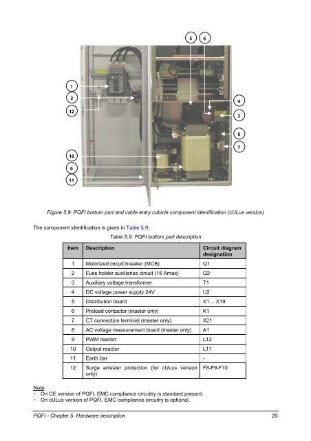
- Page 35 and 36: Table 5.10. Distribution board desc
- Page 37 and 38: The PQF Main controller board termi
- Page 39 and 40: With each IGBT module an IGBT-inter
- Page 41 and 42: 5.6.3. Active filter top part compo
- Page 43 and 44: Network voltage U (Vrms) 208 ≤ Ue
- Page 45 and 46: Figure 6.2. Top view of a typical C
- Page 47 and 48: cULus versions of PQFI are always m
- Page 49 and 50: 6.6. Mechanical preparation of a co
- Page 51 and 52: 7.3. EMC considerations The CE vers
- Page 53 and 54: For safety reasons and for proper o
- Page 55 and 56: Table 7.1. Multiplication factors X
- Page 57 and 58: Table 7.3. Allowed cable current fo
- Page 59 and 60: Sace S3-H Sace S5-H Figure 7.6. Fil
- Page 61 and 62: L1 L2 L3 To surge arrester (optiona
- Page 63 and 64: Nominal network voltage (Vrms) Tabl
- Page 65 and 66: Maximum rms current of the downstre
- Page 67 and 68: Supply side L1 L2 L3 K k l L K k l
- Page 69 and 70: LOAD 2 PQF LOAD 1 Figure 7.17. CT c
- Page 71 and 72: T1 T2 PQF PQF Figure 7.21. Case of
- Page 73 and 74: G P1, K S1, k P1 P2, L S2, l P1, K
- Page 75 and 76: AC power supply Preload circuit 3 O
- Page 77 and 78: • Routing to a slave unit Figure
- Page 79 and 80: The resulting flat cable configurat
- Page 81 and 82: WARNING: WARNING: Make sure that th
- Page 83 and 84:
+ 24 Vdc external power supply (b)
- Page 85 and 86:
The voltage applied to the external
- Page 87 and 88:
7.10.3. Cabling of warning function
- Page 89 and 90:
Table 7.17. Filter behavior as a fu
- Page 91 and 92:
24 Vdc external supply - + PQF-Mana
- Page 93 and 94:
RS-232 connection to PQF Manager Ca
- Page 95 and 96:
8. The PQF-Manager user interface 8
- Page 97 and 98:
Welcome PQF Measurements Settings P
- Page 99 and 100:
Figure 8.4. Illustration of ▲ and
- Page 101 and 102:
8.4. The PQF-Manager locking facili
- Page 103 and 104:
Table 8.5. Summary of parameters di
- Page 105 and 106:
• The line currents: (refer to Ta
- Page 107 and 108:
8.7. The ‘Settings’ menu The
- Page 109 and 110:
Before filtering After filtering Su
- Page 111 and 112:
Reactive power task requirement No
- Page 113 and 114:
Table 8.10. Overview of possible pr
- Page 115 and 116:
8.7.2. The ‘Commissioning’ menu
- Page 117 and 118:
These approaches are discussed next
- Page 119 and 120:
The most common causes for these me
- Page 121 and 122:
The filter’s advanced settings in
- Page 123 and 124:
• Modbus protocol: Choose this se
- Page 125 and 126:
DSP fault message Table 8.17. Overv
- Page 127 and 128:
In that case, check the cooling of
- Page 129 and 130:
9. The Modbus communication interfa
- Page 131 and 132:
9.3.4. RS-485 Modbus adapter termin
- Page 133 and 134:
9.7. Data access 9.7.1. PQF access
- Page 135 and 136:
9.8.5. Check the function called an
- Page 137 and 138:
9.9.5. RS-485 interface For multi-d
- Page 139 and 140:
Table 9.1. Minimum silent length be
- Page 141 and 142:
10. Commissioning instructions 10.1
- Page 143 and 144:
If in normal operation the voltage
- Page 145 and 146:
10.5.1. Automatic CT detection proc
- Page 147 and 148:
On the scopemeter screen, two wavef
- Page 149 and 150:
Supply side L1 L2 L3 K k l L K k Po
- Page 151 and 152:
• For setting up the filter’s m
- Page 153 and 154:
ABB Project: LV Active Filters PQF
- Page 155 and 156:
ABB Project: LV Active Filters PQF
- Page 157 and 158:
ABB Project: LV Active Filters PQF
- Page 159 and 160:
ABB Project: LV Active Filters PQF
- Page 161 and 162:
• Press on the PQF-Manager repeat
- Page 163 and 164:
- The hardware lock can be disengag
- Page 165 and 166:
All faults that occur are stored in
- Page 167 and 168:
12.3. Standard maintenance procedur
- Page 169 and 170:
Fan 1 capacitor X23 1 2 3 Fan 1 NC
- Page 171 and 172:
ABB Project: LV Active Filters PQF
- Page 173 and 174:
ABB Project: LV Active Filters PQF
- Page 175 and 176:
13. Troubleshooting guide 13.1. Wha
- Page 177 and 178:
Figure 13.1. PQF error treatment pr
- Page 179 and 180:
13.3.3. Tools description for a nor
- Page 181 and 182:
13.4.2. Fault tracing Table 13.2. P
- Page 183 and 184:
Table 13.4. Fault messages reported
- Page 185 and 186:
Fault message Cause What to do No s
- Page 187 and 188:
Fault message Cause What to do Unde
- Page 189 and 190:
Fault message Cause What to do •
- Page 191 and 192:
Symptom Cause / State What to do Th
- Page 193 and 194:
14. Technical specifications 14.1.
- Page 195 and 196:
General construction aspects EN-604
- Page 197:
ABB ABB n.v. Power Quality Products