Thermostats for surface mounting Series ATH-SW - doc-station.ru
Thermostats for surface mounting Series ATH-SW - doc-station.ru
Thermostats for surface mounting Series ATH-SW - doc-station.ru

Create successful ePaper yourself
Turn your PDF publications into a flip-book with our unique Google optimized e-Paper software.
M. K. JUCHHEIM GmbH & Co<br />
Delivery address:Mackenrodtstraße 14,<br />
36039 Fulda, Germany<br />
Postal address: 36035 Fulda, Germany<br />
Phone: +49 661 60 03-0<br />
Fax: +49 661 60 03-6 07<br />
E-mail: mail@jumo.net<br />
Internet: www.jumo.net<br />
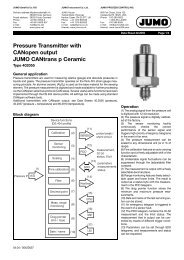
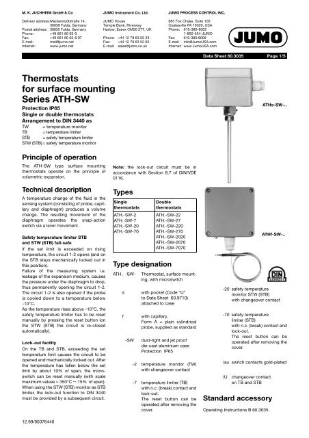
<strong>Thermostats</strong><br />
<strong>for</strong> <strong>surface</strong> <strong>mounting</strong><br />
<strong>Series</strong> <strong>ATH</strong>-<strong>SW</strong><br />
Protection IP65<br />
Single or double thermostats<br />
Arrangement to DIN 3440 as<br />
TW = temperature monitor<br />
TB = temperature limiter<br />
STB = safety temperature limiter<br />
STW (STB) = safety temperature monitor<br />
Principle of operation<br />
The <strong>ATH</strong>-<strong>SW</strong> type <strong>surface</strong> <strong>mounting</strong><br />
thermostats operate on the principle of<br />
volumetric expansion.<br />
Technical description<br />
A temperature change of the fluid in the<br />
sensing system (consisting of probe, capillary<br />
and diaphragm) produces a volume<br />
change. The resulting movement of the<br />
diaphragm operates the snap-action<br />
switch via a lever movement.<br />
Safety temperature limiter STB<br />
and STW (STB) fail-safe<br />
If the set limit is exceeded on rising<br />
temperature, the circuit 1-2 opens (and on<br />
the STB stays mechanically locked out in<br />
this position).<br />
Failure of the measuring system i.e.<br />
leakage of the expansion medium, causes<br />
the pressure under the diaphragm to drop,<br />
thus permanently opening the circuit 1-2.<br />
The circuit 1-2 is also opened if the probe<br />
is cooled down to a temperature below<br />
-10°C.<br />
As the temperature rises above -10°C, the<br />
safety temperature limiter has to be reset<br />
manually by pressing the reset button (on<br />
the STW (STB) the circuit is re-closed<br />
automatically).<br />
Lock-out facility<br />
On the TB and STB, exceeding the set<br />
temperature limit causes the circuit to be<br />
opened and mechanically locked out. After<br />
the temperature has fallen below the set<br />
limit by about 10% of span, the microswitch<br />
can be reset manually (with scale<br />
maximum values > 350°C ∼ 15% of span).<br />
When using the STW (STB) monitor as STB<br />
limiter, the lock-out function to DIN 3440<br />
must be provided by a subsequent circuit.<br />
12.99/00376440<br />
JUMO Inst<strong>ru</strong>ment Co. Ltd.<br />
JUMO House<br />
Temple Bank, Riverway<br />
Harlow, Essex CM20 2TT, UK<br />
Phone: +44 12 79 63 55 33<br />
Fax: +44 12 79 63 52 62<br />
E-mail: sales@jumo.co.uk<br />
JUMO PROCESS CONTROL INC.<br />
885 Fox Chase, Suite 103<br />
Coatesville PA 19320, USA<br />
Phone: 610-380-8002<br />
1-800-554-JUMO<br />
Fax: 610-380-8009<br />
E-mail: info@JumoUSA.com<br />
Internet: www.JumoUSA.com<br />
Note: the lock-out circuit must be in<br />
accordance with Section 8.7 of DIN/VDE<br />
0116.<br />
Types<br />
Single<br />
thermostats<br />
<strong>ATH</strong>.-<strong>SW</strong>-2<br />
<strong>ATH</strong>.-<strong>SW</strong>-7<br />
<strong>ATH</strong>.-<strong>SW</strong>-20<br />
<strong>ATH</strong>.-<strong>SW</strong>-70<br />
Double<br />
thermostats<br />
<strong>ATH</strong>.-<strong>SW</strong>-22<br />
<strong>ATH</strong>.-<strong>SW</strong>-27<br />
<strong>ATH</strong>.-<strong>SW</strong>-220<br />
<strong>ATH</strong>.-<strong>SW</strong>-270<br />
<strong>ATH</strong>.-<strong>SW</strong>-2020<br />
<strong>ATH</strong>.-<strong>SW</strong>-2070<br />
<strong>ATH</strong>.-<strong>SW</strong>-7070<br />
Type designation<br />
<strong>ATH</strong> . -<strong>SW</strong>- Thermostat, <strong>surface</strong> <strong>mounting</strong>,<br />
with microswitch<br />
s with pocket (Code “U”<br />
to Data Sheet 60.9710)<br />
attached to case<br />
f with capillary,<br />
Form A = plain cylindrical<br />
probe, supplied as standard<br />
-<strong>SW</strong> dust-tight and jet proof<br />
die-cast aluminium case<br />
Protection IP65<br />
-2 temperature monitor (TW)<br />
with changeover contact<br />
-7 temperature limiter (TB)<br />
with n.c. (break) contact and<br />
lock-out.<br />
The reset button can be<br />
operated after removing the<br />
cover.<br />
Data Sheet 60.3035<br />
Page 1/5<br />
<strong>ATH</strong>f-<strong>SW</strong>-..<br />
-20 safety temperature<br />
monitor STW (STB)<br />
with changeover contact<br />
-70 safety temperature<br />
limiter (STB)<br />
with n.c. (break) contact and<br />
lock-out.<br />
The reset button can be<br />
operated after removing the<br />
cover.<br />
/au switch contacts gold-plated<br />
/U changeover contact<br />
on TB and STB<br />
Standard accessory<br />
Operating Inst<strong>ru</strong>ctions B 60.3035.<br />
<strong>ATH</strong>s-<strong>SW</strong>-..
M. K. JUCHHEIM GmbH & Co • 36035 Fulda, Germany Data Sheet 60.3035 Page 2/5<br />
Table of ranges and probes (liquid-filled)<br />
<strong>for</strong> TW and TB<br />
Range<br />
°C<br />
–50 to +030<br />
–20 to +050<br />
–10 to +040<br />
–10 to +050<br />
–10 to +070<br />
–10 to +100<br />
+20 to +090<br />
+30 to +110<br />
+20 to +120<br />
+60 to +130<br />
+20 to +150<br />
+50 to +200<br />
+50 to +250<br />
+50 to +300<br />
+50 to +350<br />
<strong>for</strong> STW and STB<br />
Range<br />
°C<br />
+30 to +110<br />
+60 to +130<br />
+20 to +150<br />
+50 to +250<br />
+50 to +300<br />
Range<br />
AM<br />
°C<br />
+20 to +400<br />
+20 to +500<br />
+20 to +500<br />
12.99/00376440<br />
Max. probe<br />
temperature<br />
°C<br />
050<br />
060<br />
050<br />
060<br />
080<br />
125<br />
115<br />
135<br />
140<br />
150<br />
175<br />
230<br />
290<br />
345<br />
405<br />
Max. probe<br />
temperature<br />
°C<br />
135<br />
150<br />
175<br />
290<br />
345<br />
Table of ranges and probes (gas-filled)<br />
<strong>for</strong> TW and TB<br />
<strong>for</strong> STW and STB<br />
Range<br />
°C<br />
+20 to +400<br />
+20 to +500<br />
+20 to +500<br />
Max. probe<br />
temperature<br />
°C<br />
460<br />
550<br />
550<br />
Max. probe<br />
temperature<br />
°C<br />
460<br />
550<br />
550<br />
Probe length L in mm <strong>for</strong><br />
probe dia. d in mm (d = 6 is standard)<br />
5 6 7 8<br />
179<br />
201<br />
268<br />
268<br />
196<br />
146<br />
196<br />
175<br />
146<br />
191<br />
117<br />
137<br />
099<br />
083<br />
067<br />
128<br />
141<br />
185<br />
185<br />
138<br />
107<br />
138<br />
125<br />
106<br />
135<br />
088<br />
101<br />
073<br />
063<br />
053<br />
101<br />
110<br />
140<br />
140<br />
108<br />
086<br />
108<br />
099<br />
086<br />
106<br />
073<br />
082<br />
060<br />
053<br />
046<br />
085<br />
092<br />
115<br />
115<br />
091<br />
075<br />
091<br />
084<br />
075<br />
090<br />
065<br />
072<br />
054<br />
049<br />
043<br />
Probe length L in mm <strong>for</strong><br />
probe dia. d in mm (d = 6 is standard)<br />
5 6 7 8<br />
155<br />
168<br />
105<br />
088<br />
074<br />
112<br />
121<br />
080<br />
066<br />
058<br />
090<br />
096<br />
068<br />
056<br />
—<br />
078<br />
082<br />
061<br />
050<br />
—<br />
Probe length L in mm <strong>for</strong><br />
probe dia. d in mm (d = 6 is standard)<br />
5 6 7 8<br />
—<br />
217<br />
300<br />
278<br />
148<br />
202<br />
203<br />
113<br />
150<br />
158<br />
092<br />
119<br />
probe length L in mm <strong>for</strong><br />
probe dia. d in mm (d = 6 is standard)<br />
5 6 7 8<br />
261<br />
183<br />
300<br />
176<br />
127<br />
202<br />
132<br />
098<br />
150<br />
106<br />
081<br />
119<br />
Technical description<br />
Setpoint adjustment<br />
setpoint adjusted with screwdriver on setpoint<br />
spindle against internal scale after<br />
removing top of case.<br />
Switch<br />
<strong>for</strong> monitors TW, STW (STB): single-pole<br />
changeover contact.<br />
<strong>for</strong> limiters STB und TB: single-pole n.c.<br />
(break) contact on rising temperature,<br />
changeover contact at extra cost.<br />
Current rating<br />
with differentials<br />
3%, 5%, 6%, 9% : TW<br />
5%, 7%, 9% : STW (STB)<br />
— : TB, STB<br />
10 (2) A, 230 V AC, p.f. = 1 (0.6)<br />
0.25 A, 230 V DC<br />
with differentials 1.5%; TW<br />
2,5%; STW (STB)<br />
6 (1.2) A, 230 V AC, p.f. = 1 (0.6)<br />
0.15 A, 230 V DC<br />
with Code /au<br />
0.1 A, 24 V AC/DC<br />
contact resistance 2.5 — 10 mΩ<br />
Possible<br />
capillary length<br />
[m]<br />
1<br />
2<br />
4<br />
Possible<br />
capillary length<br />
[m]<br />
1<br />
2<br />
4<br />
Differential<br />
[%]<br />
5<br />
5<br />
5<br />
Differential<br />
[%]<br />
Differential<br />
in % of adjustment range<br />
with liquid-filled measuring system with gas-filled measuring system<br />
Nominal value Possible actual value Nominal value Possible actual value<br />
TW 3%<br />
6%<br />
standard<br />
on request<br />
3<br />
6<br />
max.<br />
max.<br />
4<br />
8<br />
5%<br />
9%<br />
standard<br />
on request<br />
4<br />
8<br />
max. 8,0<br />
max. 12,0<br />
1.5% at extra cost<br />
1 max. 2<br />
2% at extra cost<br />
1.5 max. 2.5<br />
STW (STB) 5% standard<br />
4 max. 6<br />
7% standard<br />
5 max. 12,0<br />
9%<br />
2%<br />
on request<br />
at extra cost<br />
8<br />
1<br />
max. 11<br />
max. 3<br />
9%<br />
2%<br />
on request<br />
at extra cost<br />
8 max. 16,0<br />
1.5 max. 3<br />
7<br />
7<br />
7
M. K. JUCHHEIM GmbH & Co 36035 Fulda, Germany Data Sheet 60.3035 Page 3/5<br />
Switching point accuracy<br />
(in % of scale span, based on setpoint or<br />
limit)<br />
in upper third of scale<br />
at start of scale<br />
DIN registration numbers<br />
<strong>ATH</strong> . -<strong>SW</strong>-2 TW 89296<br />
<strong>ATH</strong> . -<strong>SW</strong>-7 TB 89396<br />
<strong>ATH</strong> . -<strong>SW</strong>-20 STW (STB) 89496 S<br />
<strong>ATH</strong> . -<strong>SW</strong>-70 STB 89596<br />
<strong>ATH</strong> . -<strong>SW</strong>-22 TW/TW 90196<br />
<strong>ATH</strong> . -<strong>SW</strong>-27 TW/TB 90296<br />
Technical description<br />
Mean ambient temperature error,<br />
referred to scale span<br />
12.99/00376440<br />
+00<br />
- 05 %<br />
+00<br />
- 10 %<br />
Permitted ambient temperature at<br />
thermostat head and capillary<br />
In operation<br />
maximum: +80°C<br />
minimum:<br />
–40°C <strong>for</strong> end of scale below 200°C<br />
–20°C <strong>for</strong> end of scale from 200 — 350°C<br />
–40°C <strong>for</strong> end of scale from 350 — 500°C<br />
<strong>ATH</strong> . -<strong>SW</strong>-220 TW/STW (STB) 90396 S<br />
<strong>ATH</strong> . -<strong>SW</strong>-270 TW/STB 90496<br />
<strong>ATH</strong> . -<strong>SW</strong>-2020 STW (STB)/STW (STB) 90596 S<br />
<strong>ATH</strong> . -<strong>SW</strong>-2070 STW (STB)/STB 90696 S<br />
<strong>ATH</strong> . -<strong>SW</strong>-7070 STB/STB 90796<br />
There is a displacement of the switching point if the ambient temperature at the thermostat<br />
head deviates from the +22°C calibration temperature.<br />
higher ambient temperature = lower switching point<br />
lower ambient temperature = higher switching point<br />
<strong>for</strong> end of scale<br />
below 200°C +200 to +350°C +400 to +500°C<br />
TW / TB STW (STB)<br />
STB<br />
TW / TB STW (STB)<br />
STB<br />
Permitted storage temperature<br />
thermostat head, capillary, temperature<br />
probe<br />
maximum: +50°C<br />
minimum: –50°C<br />
Protection IP65 to EN 60 529<br />
Operating position unrestricted<br />
TW / TB STW (STB)<br />
STB<br />
due to thermostat head, % per °C<br />
0.08 0.17 0.06 0.13 0.14 0.12<br />
due to capillary, % per °C per m length<br />
0.047 0.054 0.09 0.11 0.04 0.03<br />
Case Material: die-cast aluminium<br />
Thermostat head <strong>mounting</strong><br />
by 2 screws through base of case (wall <strong>mounting</strong>),<br />
<strong>for</strong> types <strong>ATH</strong>f-<strong>SW</strong>-<br />
capillary exit at bottom of case<br />
Cable entry Compression gland Pg 11 DIN 46 320<br />
Capillary and probe End of scale Capillary Probe<br />
to +200°C<br />
copper 1.5 mm dia.<br />
Mat. Ref. 2.0090<br />
copper Mat. Ref. 2.0090<br />
brazed<br />
to +350°C<br />
copper 1.5 mm dia.<br />
Mat. Ref. 2.0090<br />
st. steel Mat. Ref. 1.4571<br />
brazed<br />
to +500°C<br />
st. steel 1.5 mm dia.<br />
Mat. Ref. 1.4571<br />
at extra cost<br />
st. steel Mat. Ref. 1.4571<br />
welded<br />
to +350°C<br />
st. steel 1.5 mm dia.<br />
Mat. Ref. 1.4571<br />
st. steel Mat. Ref. 1.4571<br />
welded<br />
Minimum bending radius 5 mm<br />
Capillary lengths 1 m standard; up to max. 5 m on request
M. K. JUCHHEIM GmbH & Co 36035 Fulda, Germany Data Sheet 60.3035 Page 4/5<br />
Probe <strong>for</strong>ms and<br />
pockets to<br />
Data Sheet<br />
60.9710<br />
V-Note<br />
At present there is<br />
no restrictive statement<br />
from the health<br />
authorities concerning<br />
any danger to<br />
health over short<br />
periods and at low<br />
concentrations, e.g.<br />
after fracture of the<br />
measuring system.<br />
12.99/00376440<br />
Models <strong>ATH</strong>s-<strong>SW</strong>-..<br />
U up to +150°C probe temperature<br />
Screw-in pocket with fixing screw <strong>for</strong> securing on case spigot. Male thread ½" pipe with sealing<br />
shoulder, DIN 3852/2-A, normally brass.<br />
UZ * above +150°C probe temperature<br />
with extension so that the maximum permitted ambient temperature +80°C at case is not<br />
exceeded. Male thread ½" pipe, with sealing shoulder, DIN 3852/2-A, 27 mm a/f, steel.<br />
Models <strong>ATH</strong>f-<strong>SW</strong>-..<br />
U Screw-in pocket with fixing screw (clip <strong>for</strong> clamping the probe). Male thread ½" pipe with sealing<br />
shoulder, DIN 3852/2-A, 27 mm a/f, normally brass.<br />
* above +150°C<br />
Male thread ½" pipe with sealing shoulder, DIN 3852/2-A, 27 mm a/f, steel.<br />
* Pockets U, UZ: <strong>for</strong> compressive-load applications above +300°C, material on enquiry !<br />
Physical and toxicological properties of the expansion media which may escape in the event of a system fracture!<br />
Ranges with<br />
end of scale<br />
°C<br />
below +200°C<br />
+200 to +350°C<br />
+350 to +500°C<br />
Connection diagrams<br />
( 1 )<br />
( 2 )<br />
( 4 )<br />
Dangerous<br />
reactions<br />
—<br />
—<br />
—<br />
Fire/explosion hazard Water<br />
Ignition<br />
temperature<br />
°C<br />
+280<br />
+490<br />
—<br />
Explosion<br />
limit<br />
% v/v<br />
1.2 - 7.5<br />
1.0 - 3.5<br />
—<br />
Code 2, 20 with changeover contact Code 7, 70 with n.c. (break) contact and<br />
lock-out<br />
( 4 ) ( 2 ) ( 1 )<br />
Code 27, 270<br />
System I with changeover contact<br />
System II with n.c. (break) contact and<br />
lock-out<br />
( 4 ) ( 2 ) ( 1 ) ( 1 ) ( 4 ) ( 2 )<br />
( 1 )<br />
( 2 )<br />
Code 27, 270<br />
System I with changeover contact<br />
System II with changeover contact and<br />
lock-out<br />
( 1 )<br />
( 2 )<br />
( 1 )<br />
( 2 )<br />
( 4 )<br />
( 4 ) ( 2 ) ( 1 )<br />
Code 22, 220, 2020<br />
System I and II with changeover contact<br />
contamination<br />
K<br />
X<br />
X<br />
—<br />
Toxicological data<br />
irritant danger to<br />
health<br />
X<br />
X<br />
—<br />
X<br />
X<br />
—<br />
toxic<br />
—<br />
—<br />
—<br />
( 1 ) ( 4 ) ( 2 )<br />
Code 7, 70 with changeover contact and<br />
lock-out<br />
( 1 )<br />
( 4 ) ( 2 )<br />
( 1 )<br />
( 4 ) ( 2 )<br />
STB / STB<br />
Code 7070<br />
with changeover contact and<br />
lock-out<br />
( 2 )<br />
( 1 )<br />
STB / STB<br />
Code 7070<br />
with n.c. (break) contact and<br />
lock-out<br />
( 1<br />
( 2
M. K. JUCHHEIM GmbH & Co 36035 Fulda, Germany Data Sheet 60.3035 Page 5/5<br />
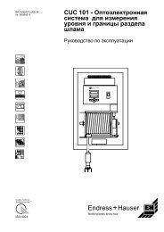
Dimensions<br />
<strong>ATH</strong>-<strong>SW</strong>-..<br />
12.99/00376440<br />
compression gland<br />
PG 11<br />
Ordering example<br />
Single thermostat<br />
Type : <strong>ATH</strong>s-<strong>SW</strong>-2<br />
Range : 0 to +100°C<br />
Differential : 3%<br />
Mounting : U ½" nichrome<br />
Probe : 8 x 200 mm nichrome<br />
Double thermostat<br />
Type : <strong>ATH</strong>f-<strong>SW</strong>-270<br />
Range : +30 to +110°C<br />
Differential : 3%<br />
Capillary : 2 m copper<br />
Mounting : U ½" brass<br />
Probe : 15 x 150 mm brass<br />
hex<br />
<strong>ATH</strong>s-<strong>SW</strong>-..<br />
compression gland<br />
PG 11