Doppler Current Sensor 4100/4100R
Doppler Current Sensor 4100/4100R
Doppler Current Sensor 4100/4100R

You also want an ePaper? Increase the reach of your titles
YUMPU automatically turns print PDFs into web optimized ePapers that Google loves.
<strong>Doppler</strong> <strong>Current</strong> <strong>Sensor</strong> <strong>4100</strong>/<strong>4100</strong>R<br />
D359 - January 2008<br />
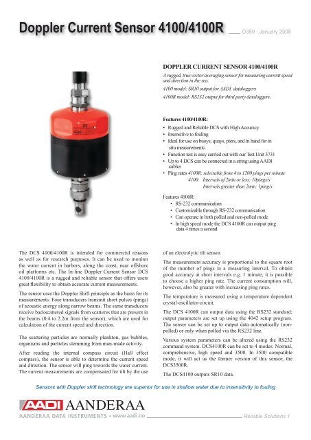
DOPPLER CURRENT SENSOR <strong>4100</strong>/<strong>4100</strong>R<br />
A rugged, true vector averaging sensor for measuring current speed<br />
and direction in the sea.<br />
<strong>4100</strong> model: SR10 output for AADI dataloggers<br />
<strong>4100</strong>R model: RS232 output for third party dataloggers.<br />
Features <strong>4100</strong>/<strong>4100</strong>R:<br />
• Rugged and Reliable DCS with High Accuracy<br />
• Insensitive to fouling<br />
• Ideal for use on buoys, quays, piers, and in hand for in<br />
situ measurements<br />
• Function test is easy carried out with our Test Unit 3731<br />
• Up to 4 DCS can be connected in a string using AADI<br />
cables<br />
• Ping rates <strong>4100</strong>R: selectable from 4 to 1200 pings per minute<br />
<strong>4100</strong>: Intervals of 2min or less: 10pings/s<br />
Intervals greater than 2min: 1ping/s<br />
Features <strong>4100</strong>R:<br />
• RS-232 communication<br />
• Customizable through RS-232 communication<br />
• Can operate in both polled and non-polled mode<br />
• In high speed mode the DCS <strong>4100</strong>R can output ping<br />
data 4 times a second<br />
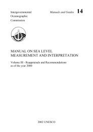
The DCS <strong>4100</strong>/<strong>4100</strong>R is intended for commercial reasons<br />
as well as for research purposes. It can be used to monitor<br />
the water current in harbors, along the coast, near offshore<br />
oil platforms etc. The In-line <strong>Doppler</strong> <strong>Current</strong> <strong>Sensor</strong> DCS<br />
<strong>4100</strong>/<strong>4100</strong>R is a rugged and reliable sensor that offers users<br />
great flexibility to obtain accurate current measurements.<br />
The sensor uses the <strong>Doppler</strong> Shift principle as the basis for its<br />
measurements. Four transducers transmit short pulses (pings)<br />
of acoustic energy along narrow beams. The same transducers<br />
receive backscattered signals from scatteres that are present in<br />
the beams (0.4 to 2.2m from the sensor), which are used for<br />
calculation of the current speed and direction.<br />
The scattering particles are normally plankton, gas bubbles,<br />
organisms and particles stemming from man-made activity.<br />
After reading the internal compass circuit (Hall effect<br />
compass), the sensor is able to determine the current speed<br />
and direction. The sensor will ping towards the water current.<br />
The current measurements are compensated for tilt by the use<br />
of an electrolytic tilt sensor.<br />
The measurement accuracy is proportional to the square root<br />
of the number of pings in a measuring interval. To obtain<br />
good accuracy at short intervals e.g. 1 minute, it is possible<br />
to choose a higher ping rate. The current consumption will,<br />
however, also be greater with increasing ping rates.<br />
The temperature is measured using a temperature dependent<br />
crystal-oscillator-circuit.<br />
The DCS <strong>4100</strong>R can output data using the RS232 standard;<br />
output parameters are set up using the 4042 setup program.<br />
The sensor can be set up to output data automatically (nonpolled)<br />
or only when polled via the RS232 line.<br />
Various system parameters can be altered using the RS232<br />
command system. DCS<strong>4100</strong>R can be set to 4 modes: Normal,<br />
comprehensive, high speed and 3500. In 3500 compatible<br />
mode, it will act as the former version of this sensor, the<br />
DCS3500R.<br />
The DCS<strong>4100</strong> outputs SR10 data.<br />
<strong>Sensor</strong>s with <strong>Doppler</strong> shift technology are superior for use in shallow water due to insensitivity to fouling<br />
Reliable Solutions 1
Specifications D359 - January 2008<br />
<br />
<br />
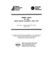
Pin Configuration <strong>4100</strong>R:<br />
External view. Pin = ; Bushing=<br />
Bridge ground<br />
Control voltage<br />
Bridge voltage<br />
Positive supply (+9V)<br />
Negative supply (gnd)<br />
TX RS 232 output<br />
RX RS 232 input<br />
5<br />
6<br />
4<br />
3<br />
7<br />
2<br />
1<br />
8<br />
9<br />
<br />
14<br />
13<br />
15<br />
16<br />
12<br />
17<br />
18<br />
11<br />
10<br />
Ch.4 Water<br />
Ch.3 <strong>Current</strong> direction<br />
Ch.2 <strong>Current</strong> speed<br />
All connections wired through from upper to lower receptacle<br />
Pin Configuration <strong>4100</strong>: ( pp p )<br />
External view. Pin = ; Bushing=<br />
Bridge ground<br />
Control voltage<br />
Bridge voltage<br />
System ground<br />
–9 volt<br />
dimensions in mm<br />
5<br />
6<br />
4<br />
3<br />
7<br />
2<br />
1<br />
8<br />
9<br />
14<br />
13<br />
15<br />
16<br />
12<br />
17<br />
18<br />
11<br />
10<br />
Ch.4 Water Temp.<br />
Ch.3 <strong>Current</strong> direction<br />
Ch.2 <strong>Current</strong> speed<br />
Optional Accessories <strong>4100</strong>R:<br />
- Setup software 4042 (included)<br />
- Maintenance Kit 3932<br />
- Up to 4 DCS can be used in a string interconnected by 3 ea<br />
Cables 3802/3808. Cable length must be specified<br />
- Cable 3803/3807 with one free end connects the upper DCS<br />
to the data reading device. Maximum length between the<br />
bottom DCS and the reading device is 15 meters<br />
- Cable 3904 with 9-pin D-SUB connector to PC<br />
- Power supply 3786, 12V/3A<br />
- Test Unit 3731<br />
<strong>Current</strong> Speed (vector averaged):<br />
Available ranges:<br />
P/N <strong>4100</strong>/<strong>4100</strong>R 0 - 300 cm/s standard<br />
P/N <strong>4100</strong>A/<strong>4100</strong>RA 0 - 500 cm/s on request<br />
Resolution:<br />
0.1% of FS<br />
Accuracy:<br />
Absolute:<br />
±0.15 cm/s<br />
Relative:<br />
±1% of reading<br />
Statistic precision: 0.55 cm/s (Standard deviation)<br />
<strong>Current</strong> Direction (vector averaged):<br />
Range:<br />
0-360° magnetic.<br />
Resolution: 0.35°<br />
Accuracy:<br />
±5° for 0-15° tilt.<br />
±7.5° for 15-35° tilt.<br />
Temperature:<br />
Range: -10 to 43°C<br />
Resolution:<br />
0.05°C<br />
Accuracy*:<br />
±0.08°C<br />
Tilt Circuit:<br />
Accuracy: ±1.5°<br />
Compass Circuit:<br />
Accuracy: ±3°<br />
RS 232 Output: 9600 Baud, 8 data bit, No parity, 2<br />
stop bits<br />
Acoustic Frequency: 2MHz<br />
Acoustic Power: 25W in 1ms pulses<br />
Beam Angle:<br />
±1° (Main lobe)<br />
Installation distance: Minimum 0.5m from the bottom<br />
(to the DCS head) Minimum 0.75m from the surface<br />
<strong>Current</strong> consumption: 6mA · Ping rate<br />
(ping rate in pings per second)<br />
Supply Voltage: 7-14VDC<br />
Operating Temp.: -10 to +50°C<br />
Depth Capability: 300 meters<br />
Electrical Connection: 18-pin Strain-proof Plug<br />
Breaking Load: 1500kg<br />
Material and Finish: Durotong, Titanium, POM,<br />
Stainless Steal<br />
Net. Weight:<br />
1815 grams<br />
Warranty:<br />
Two years against faulty materials<br />
and workmanship. For subsurface<br />
cables: contact factory<br />
*) DCS<strong>4100</strong>: Different coefficient set for each ping rate.<br />
DCS<strong>4100</strong>R: The accuracy is only valid for factory default<br />
settings. For other settings, please contact factory.<br />
Optional Accessories <strong>4100</strong>:<br />
- Maintenance Kit 3932<br />
- Up to 4 DCS can be used in a string interconnected by 3 ea<br />
cable 3810<br />
- Cable to Reading Unit: 3863/3809/3852<br />
- Test Unit 3731<br />
Reliable Solutions 2
DCS <strong>4100</strong>R Outputs<br />
D359 -January 2008<br />
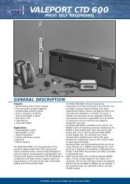
Available output parameters<br />
from the DCS <strong>4100</strong>R RS232<br />
line<br />
Compass<br />
Compensation<br />
ON<br />
Comprehensive<br />
Compass<br />
Compensation<br />
OFF<br />
Output Mode<br />
Compass<br />
Compensation<br />
ON<br />
Normal<br />
Compass<br />
Compensation<br />
OFF<br />
High<br />
Speed<br />
R P R P R P R P<br />
<strong>Current</strong> speed long the x-axis <br />
<strong>Current</strong> speed long the y-axis <br />
<strong>Current</strong> speed North <br />
<strong>Current</strong> speed East <br />
Absolute current speed <br />
<strong>Current</strong> direction ref to North <br />
<strong>Current</strong> direction ref to x-axis <br />
Signal strength <br />
Compass direction <br />
Tilt along the x-axis <br />
Tilt along the y-axis <br />
Tilt along the North axis <br />
Tilt along the East axis <br />
Ping count <br />
Water temperature <br />
Time series from AD converter<br />
R: Rectangular output<br />
P: Polar output<br />
Time series are available in polled mode using a poll command<br />
3500<br />
Test Unit 3731 for DCS<strong>4100</strong>/<strong>4100</strong>R<br />
The Test Unit is designed to verify that vital parts<br />
of the <strong>Doppler</strong> <strong>Current</strong> <strong>Sensor</strong> (DCS) are working<br />
correctly. The Test Unit is designed for DCS<br />
installed on the RCM9, RCM11 and for stand<br />
alone DCS in the 3500/3900/3920/3990/<strong>4100</strong><br />
series.<br />
DCS <strong>4100</strong>/<strong>4100</strong>R<br />
under test<br />
DISPLAY UNIT 3315<br />
Serial No:<br />
The Test Unit consists of a ring with 4 test<br />
transducers suspended by mechanical springs,<br />
enabling each test transducer to be pressed<br />
against the DCS transducers.<br />
The test transducers pick up some of the energy<br />
transmitted by the ‘ping’ from the DCS. This<br />
energy is used to start oscillation of the test<br />
transducers. In the receiving stage of the DCS<br />
the test transducers are still oscillating and thus<br />
transmitting a weak signal back to the DCS.<br />
TEST UNIT 3731 (for DCS)<br />
Serial No.<br />
AANDERAA<br />
INSTRUMENTS<br />
5852 BERGEN,NORWAY. TEL.+47 55 109900<br />
Test Unit 3731<br />
Direction<br />
Slot<br />
Simulated<br />
<strong>Current</strong><br />
Test<br />
Transducer<br />
Made by<br />
AANDERAA BERGEN<br />
INSTRUMENTS NORWAY<br />
CHANNELS 1–4<br />
CHANNELS 1–3<br />
CHANNELS 1–5<br />
CHANNELS 1–2<br />
HOURS ON<br />
CHANNEL 1<br />
PDC-4 INT./<br />
AVR. TIME<br />
OFF<br />
COEFF A&B<br />
COEFF C&D<br />
INPUT<br />
OUTPUT<br />
CH. 1–5 CH. 1 RS-232C, PDC-4<br />
Please refer data sheet D320 for information about the operating procedure.<br />
Reliable Solutions 3
Recording Int: 10 min. No. of Channels: 4<br />
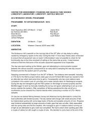
Applications<br />
Use DCS <strong>4100</strong> together with Aanderaa dataloggers and DCS <strong>4100</strong>R<br />
(RS232 output) together with 3. party datalogger. Refer specifications<br />
on page 2 for information about cables and other part numbers.<br />
Allways install the DCS at least 2.2m from any obstruction for<br />
correct measurements!<br />
DCS <strong>4100</strong> in a buoy deployment, CMB 4280<br />
The DCS <strong>4100</strong> is placed inside a central PVC tube at 1m depth, which<br />
gives a symmetrical installation with minimal interference from the buoy<br />
structure. The buoy can be equipped with up to three DCS <strong>4100</strong> and<br />
also sensors for wave and atmospheric parameters. Data can be relayed<br />
ashore by VHF radio where the data is displayed or conveyed further by<br />
telephone. See Data Sheet D 299 for further information.<br />
2.5 m<br />
D359 - January 2008<br />
Cable to<br />
RS-232 data<br />
reading device.<br />
One free end<br />
DCS <strong>4100</strong>#1/<br />
DCS <strong>4100</strong>R#1<br />
Interconnecting<br />
Cable<br />
DCS <strong>4100</strong>#2/<br />
DCS <strong>4100</strong>R#2<br />
DCS <strong>4100</strong>/<strong>4100</strong>R in a string<br />
Up to 4 DCS <strong>4100</strong>/<strong>4100</strong>R can be connected in a string. Use an open<br />
end cable between the upper DCS and the Reading Unit. Use an<br />
interconnecting cable between each DCS. The open end cable exposes<br />
positive supply, GND and Rx/Tx lines for 4 DCS. The recommended<br />
maximum distance between the bottom DCS and the data reading<br />
equipment connected to the open end cable is 15 meters. Additional<br />
sensors can be connected below and between the DCS, use RS232<br />
sensor together with DCS<strong>4100</strong>R and SR10 sensors together with<br />
DCS<strong>4100</strong>. NOTE! The standard cables allows 11 parameters to be send<br />
to the Reading Unit, contact factory for optional cables.<br />
1.9 m<br />
Max<br />
15m<br />
Interconnecting<br />
Cable<br />
DCS <strong>4100</strong>#3/<br />
DCS <strong>4100</strong>R#3<br />
Interconnecting<br />
Cable<br />
DCS <strong>4100</strong>/<strong>4100</strong>R installed on a pier/single point<br />
The DCS can be moored under the pier with an anchor. The cable from<br />
the sensor should be fastened to the pier and kept tight thus keeping the<br />
sensor horizontal and in a fixed position. Use an open end cable between<br />
the DCS and the Reading Unit. Maximum cable length is 500m. DCS<br />
<strong>4100</strong> can be connected to Display Unit 3315 for real-time measurements<br />
in engineering units. Additional sensors can be connected to the cable.<br />
DCS <strong>4100</strong>R and High speed mode<br />
In comprehensive mode and normal mode, the DCS will collect a<br />
number of ping sets and then perform an averaging of this data. When<br />
using the highspeed<br />
Display Unit 3315<br />
mode, the DCS outputs<br />
Fly lead<br />
Display Unit 3315<br />
uncompensated data<br />
from each ping set<br />
(<strong>Current</strong> speed X/Y,<br />
Compass direction,<br />
Tilt X/Y, and water<br />
temperature). This<br />
data can be output<br />
at a rate of 4 times a<br />
second.<br />
Cable 3653<br />
up to 300m long<br />
In-Line<br />
<strong>Doppler</strong> <strong>Current</strong><br />
<strong>Sensor</strong> <strong>4100</strong><br />
Conductivity<br />
<strong>Sensor</strong><br />
Data Storage<br />
Unit 2990<br />
(Optional)<br />
Buoy deployment<br />
Cable 3809<br />
Datalogger 3634 with<br />
back-up memory<br />
02 WATER LEVEL 18.26 M<br />
<strong>Doppler</strong> <strong>Current</strong><br />
<strong>Sensor</strong> DCS <strong>4100</strong><br />
0.4m<br />
Measuring area<br />
1.8m<br />
Raw data to DSU 2990<br />
Powered by Battery or<br />
from Mains via an<br />
AC/DC Adapter<br />
Data in RS 232C<br />
format to PC<br />
DCS <strong>4100</strong>#4/<br />
DCS <strong>4100</strong>R#4<br />
Anchoring rope<br />
String deployment<br />
Measurements from a pier<br />
5851 BERGEN, NORWAY<br />
TEL. +47 55 60 48 00<br />
FAX. +47 55 60 48 01<br />
Single point<br />
http://www.aadi.no<br />
e-mail: info@aadi.no<br />
Representative’s Stamp<br />
Reliable Solutions 4