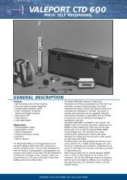
Manual on sea level measurement and ... - unesdoc - Unesco
Manual on sea level measurement and ... - unesdoc - Unesco
Manual on sea level measurement and ... - unesdoc - Unesco
- No tags were found...

Create successful ePaper yourself
Turn your PDF publications into a flip-book with our unique Google optimized e-Paper software.
IntergovernmentalOceanographicCommissi<strong>on</strong><str<strong>on</strong>g>Manual</str<strong>on</strong>g>s <strong>and</strong> GuidesMANUAL ON SEA LEVELMEASUREMENT AND INTERPRETATIONVolume III - Reappraisals <strong>and</strong> Recommendati<strong>on</strong>sas of the year 20002002 UNESCO
IntergovernmentalOceanographicCommissi<strong>on</strong><str<strong>on</strong>g>Manual</str<strong>on</strong>g>s <strong>and</strong> GuidesMANUAL ON SEA LEVELMEASUREMENT AND INTERPRETATIONVolume III - Reappraisals <strong>and</strong> Recommendati<strong>on</strong>sas of the year 20002002 UNESCO
IOC <str<strong>on</strong>g>Manual</str<strong>on</strong>g>s <strong>and</strong> Guides No. 14, Volume IIIFebruary 2002English <strong>on</strong>ly(SC-2002/WS/10)
FOREWORDIn 1985 the Intergovernmental Oceanographic Commissi<strong>on</strong> (IOC) published the “<str<strong>on</strong>g>Manual</str<strong>on</strong>g> <strong>on</strong>Sea Level Measurement <strong>and</strong> Interpretati<strong>on</strong>” as part of its <str<strong>on</strong>g>Manual</str<strong>on</strong>g>s <strong>and</strong> Guides series (Number 14). Themanual had been prepared by the staff of the Institute of Oceanographic Science, Bidst<strong>on</strong> Observatory,UK (now the Proudman Oceanographic Laboratory) who had been associated with summer courses <strong>on</strong><strong>sea</strong>-<strong>level</strong> observati<strong>on</strong> <strong>and</strong> data reducti<strong>on</strong> held under the auspices of IOC in support of the recentlyestablished Global Sea Level Observing System (GLOSS) programme. The manual was c<strong>on</strong>cernedalmost entirely with the float tide gauge technology then used at most locati<strong>on</strong>s around the world. In1994 the original manual was reprinted as Number 14, Volume 1 (Basic Procedures) <strong>and</strong> an additi<strong>on</strong>aldocument was published as Volume 2 (Emerging Technologies) which summarized new developmentsin the field. These two volumes have served as the basic training materials for IOC <strong>sea</strong> <strong>level</strong> coursesheld in many countries up to the present.At the sixth meeting of the GLOSS Group of Experts in Toulouse in 1999, the decisi<strong>on</strong> wasmade to embark <strong>on</strong> a partial-rewriting of the two old volumes into a new document (Volume 3) whichwould update the informati<strong>on</strong> <strong>on</strong> the rapidly developing different technologies <strong>and</strong> which wouldprovide updates to other informati<strong>on</strong> <strong>on</strong> GLOSS. The decisi<strong>on</strong> was made for two main reas<strong>on</strong>s. First, itis clear that there will be a need for a c<strong>on</strong>siderably greater amount of <strong>sea</strong> <strong>level</strong>-related training in thenext decade as programmes such as C-GOOS add to the requirements of GLOSS. C<strong>on</strong>sequently, thereis a need to get our training materials in better order <strong>and</strong> up-to-date. Sec<strong>on</strong>d, it was our intenti<strong>on</strong> thatthe new document would make firmer statements of what c<strong>on</strong>stitutes a suitable technology for GLOSS,rather than just review the available technologies as the earlier volumes did.This new Volume 3 simply refers back to secti<strong>on</strong>s in the earlier volumes if we felt there was nothing tochange or new to add, even if it must be admitted that the style of the old volumes is now somewhatdated. This does not imply that we c<strong>on</strong>sidered the old material was not worth including in the newvolume. In fact, much of the c<strong>on</strong>tents of Volumes 1 <strong>and</strong> 2 (e.g., the descripti<strong>on</strong> of float gaugeoperati<strong>on</strong>s using paper charts) is still valid <strong>and</strong> educati<strong>on</strong>al. Rather, our decisi<strong>on</strong> was taken knowingthat Volumes 1 <strong>and</strong> 2 can still readily be found <strong>on</strong> the web at:http://www.pol.ac.uk/psmsl/training/training.htmlVolume 3 also uses web references for other reas<strong>on</strong>s. For example, it has enabled us to producethis document in a reas<strong>on</strong>able time without the worry that some of its c<strong>on</strong>tents (lists of addresses etc.)will be out-of-date as so<strong>on</strong> as it is printed. We intend to keep as many as possible of the web addressesthe same over the next few years while keeping their c<strong>on</strong>tents as up-to-date as possible.We hope that this new Volume 3 will fulfil its objectives <strong>and</strong> that it will c<strong>on</strong>tribute towardsunifying procedures for <strong>sea</strong>-<strong>level</strong> <strong>measurement</strong>s in Member States of IOC who wish to install orreactivate <strong>sea</strong>-<strong>level</strong> stati<strong>on</strong>s. The GLOSS Group of Experts has endorsed its publicati<strong>on</strong>, <strong>and</strong> membersof the Group are thanked for c<strong>on</strong>tributing towards its preparati<strong>on</strong>.Philip L. Woodworth, Chairman IOC GLOSS Group of Experts, Email psmsl@pol.ac.ukThorkild Aarup, GLOSS Technical Secretary, Email t.aarup@unesco.orgMarch 2000
IOC <str<strong>on</strong>g>Manual</str<strong>on</strong>g>s <strong>and</strong> Guides No. 14Volume III - page (i)TABLE OF CONTENTSpage1. INTRODUCTION....................................................................................................................... 11.1 HISTORICAL BACKGROUND ..................................................................................................11.2 TIDE GAUGES.............................................................................................................................11.3 GLOSS REQUIREMENTS...........................................................................................................21.4 LAYOUT OF VOLUME 3 ...........................................................................................................32. TIDE GAUGE TECHNOLOGIES............................................................................................ 32.1 ACOUSTIC TIDE GAUGES........................................................................................................32.1.1 Acoustic Gauges With Sounding Tubes ......................................................................... 42.1.1.1 The NOAA NGWLMS System..........................................................................................42.1.1.2 The Australian SEAFRAME System ...............................................................................52.1.1.3 Other Users of Acoustic Sounding Tube Gauges <strong>and</strong> Calibrati<strong>on</strong> Comments...............62.1.1.4 Similar Hardware Available...........................................................................................62.1.2 Acoustic Gauges in the Open Air.................................................................................... 72.1.2.1 Experience in Spain ........................................................................................................72.1.2.2 Experience in South Africa .............................................................................................82.2 PRESSURE SENSOR TIDE GAUGES........................................................................................82.2.1 Single Transducer Systems.............................................................................................. 92.2.1.1 The Datum of a Single Transducer Pressure System....................................................102.2.2 Multiple Pressure Transducer Systems (‘B Gauges’)................................................. 102.2.3 Pressure Transducers in Stilling Wells ........................................................................ 112.2.4 Bubbler Pressure Gauges .............................................................................................. 112.2.5 Bottom Mounted Pressure Gauges ............................................................................... 122.3 FLOAT GAUGES IN STILLING WELLS.................................................................................122.4 RADAR TIDE GAUGES AND OTHER NEW TECHNOLOGIES...........................................132.5 GENERAL PRINCIPLES OF CHOICE OF A TIDE GAUGE SITE .........................................142.6 COMMENTS ON DESIRABLE RECORDING FREQUENCY................................................152.7 SYNTHESIS OF THE MERITS OF DIFFERENT TECHNOLOGIES .....................................163. DATA TRANSMISSION METHODS .................................................................................... 273.1 INTRODUCTION.......................................................................................................................273.2 SATELLITE AND GLOBAL MOBILE PHONE DATA LINKS..............................................283.3 PACKAGES AVAILABLE WITHIN GLOSS ...........................................................................284. DATUMS AND DATUM CONNECTIONS AT TIDE GAUGES........................................ 294.1 SOME DEFINITIONS (EXTENDED FROM VOLUME 1)......................................................294.2 LEVELLING BETWEEN LOCAL BENCHMARKS................................................................324.3 LEVELLING BETWEEN WIDER AREA MARKS..................................................................324.4 GEODETIC FIXING OF TIDE GAUGE BENCHMARKS.......................................................334.4.1 Introducti<strong>on</strong> .................................................................................................................... 334.4.2 Geocentric Co-ordinates of Tide Gauge Benchmarks <strong>and</strong> M<strong>on</strong>itoring of VerticalL<strong>and</strong> Movements at Tide Gauges ................................................................................. 334.4.3 GPS Measurements ........................................................................................................ 344.4.4 DORIS Measurements ................................................................................................... 364.4.5 Absolute Gravity Measurements .................................................................................. 364.5 GEODETIC CONTACT POINTS ..............................................................................................37
IOC <str<strong>on</strong>g>Manual</str<strong>on</strong>g>s <strong>and</strong> Guids No. 14Volume III - page ii5. DATA DOCUMENTATION AND PROCESSING............................................................... 385.1 DOCUMENTATION AND ARCHIVING .................................................................................385.2 PC-BASED SOFTWARE ...........................................................................................................385.2.1 Comments <strong>on</strong> Tidal Predicti<strong>on</strong>s.................................................................................... 395.2.2 Tidal Filters for ‘Mean Sea Level’................................................................................ 395.2.3 Comments <strong>on</strong> Computati<strong>on</strong>s of Extremes.................................................................... 406. DATA EXCHANGE PROCEDURES..................................................................................... 416.1 BACKGROUND.........................................................................................................................416.2 CONSEQUENT DATA EXCHANGE ACTIONS .....................................................................426.3 FAST DELIVERY DATA ..........................................................................................................426.4 REGIONAL PROGRAMMES....................................................................................................437. TRAINING MATERIALS, TRAINING COURSES AND MORE INFORMATION ....... 437.1 TRAINING MATERIALS ..........................................................................................................437.2 SEA LEVEL TRAINING COURSES.........................................................................................437.3 FURTHER INFORMATION .....................................................................................................448. REFERENCES.......................................................................................................................... 449. ACKNOWLEDGEMENTS...................................................................................................... 47pageAPPENDICES1. GLOSS REQUIREMENTS FOR GAUGES2. LIST OF ACRONYMS
IOC <str<strong>on</strong>g>Manual</str<strong>on</strong>g>s <strong>and</strong> Guides No. 14Volume III1. INTRODUCTION1.1 HISTORICAL BACKGROUNDSince ancient times observers of the ocean have attempted the <strong>measurement</strong> of changes in <strong>sea</strong><strong>level</strong> in order to underst<strong>and</strong> the mechanisms resp<strong>on</strong>sible for phenomena such as the tides <strong>and</strong> thecatastrophic floods due to storms <strong>and</strong> tsunamis. The study of the ocean tides has a particularly richhistory, with even prehistoric societies able to associate the regular changes in the <strong>level</strong> of the <strong>sea</strong> tothe movements of the Mo<strong>on</strong> <strong>and</strong> Sun, while in more recent times tidal studies have preoccupied someof the world’s greatest scientists. It is now known that <strong>sea</strong> <strong>level</strong> changes <strong>on</strong> all timescales fromsec<strong>on</strong>ds (due to wind waves) through to milli<strong>on</strong>s of years (due to the movement of c<strong>on</strong>tinents). Astudent interested in the history <strong>and</strong> science of tides <strong>and</strong> <strong>sea</strong> <strong>level</strong> changes could begin by reading Pugh(1987), Open University (1989), Emery <strong>and</strong> Aubrey (1991), Bijlsma et al. (1996), Pirazzoli (1996),Warrick et al. (1996), Cartwright (1999) <strong>and</strong> Douglas <strong>and</strong> Kearney (2000).This manual is c<strong>on</strong>cerned primarily with techniques for the <strong>measurement</strong> of what are calledrelative <strong>sea</strong> <strong>level</strong> changes which means changes relative to the <strong>level</strong> of the l<strong>and</strong> up<strong>on</strong> which themeasuring instrument (the tide gauge) is located. The subject of changes in the <strong>level</strong> of l<strong>and</strong> itself isreviewed later in this document but is given more detailed presentati<strong>on</strong> in other reports to which werefer. The manual also c<strong>on</strong>cerns itself primarily with the part of the frequency spectrum of <strong>sea</strong> <strong>level</strong>change from minutes through to centuries by means of in situ devices at the coast (tide gauges). Suchchanges are sometimes called still water <strong>level</strong> changes, being changes over a period l<strong>on</strong>g enough toaverage over wind waves. The devices employed to make these <strong>measurement</strong>s are usually called tidegauges, although <strong>sea</strong> <strong>level</strong> recorders might be a more appropriate term. In this manual we have keptthe older, c<strong>on</strong>venti<strong>on</strong>al term.Tide gauges themselves have a l<strong>on</strong>g history. The first devices were simply graduated markingsinscribed <strong>on</strong> rocks, or <strong>on</strong> mas<strong>on</strong>ry or boards at the entrances to harbours, with <strong>measurement</strong>s of <strong>sea</strong><strong>level</strong> made visually. The l<strong>on</strong>g <strong>sea</strong> <strong>level</strong> records collected from several European ports (e.g. Amsterdam,Stockholm, Brest <strong>and</strong> Liverpool) were all obtained this way, with most <strong>measurement</strong>s restricted toobservati<strong>on</strong>s of just high <strong>and</strong> low water <strong>level</strong>s. These data sets of Mean High Water, Mean LowWater <strong>and</strong> their combinati<strong>on</strong> into Mean Tide Level have proved to be of great importance to climatechange studies. Only in the 1830’s did the first mechanical gauges appear in near to modern form,equipped with clocks <strong>and</strong> chart recorders <strong>and</strong> with a stilling well <strong>and</strong> float arrangement for the dampingof high frequency wave activity. These provided the first, routine (although not the first overall) meansof <strong>measurement</strong> of the complete tidal curve which could be inspected in detail by digitizati<strong>on</strong> (typicallyevery hour) of the pen traces <strong>on</strong> the paper charts, <strong>and</strong> which could thereby provide a determinati<strong>on</strong> ofMean Sea Level, or a true average of the <strong>sea</strong> <strong>level</strong> over a period such as a m<strong>on</strong>th or a year.1.2 TIDE GAUGESTide gauges nowadays come in many different forms (for a recent review, see Joseph, 1999).The well-known float gauge in a stilling well remains a popular type, although electr<strong>on</strong>ic digitizati<strong>on</strong> ofthe rise <strong>and</strong> fall of the float has replaced the chart recorder. Gauges can also be purchased based <strong>on</strong> theprinciples of the <strong>measurement</strong> of sub-surface pressure, or of the time-of-flight of a pulse of sound, or ofa pulse of radar. Gauges have been developed using stepped sensor techniques <strong>and</strong> other ingeniousmethods. Al<strong>on</strong>gside the range of available technologies, there is a range of prices which can be paid forsimilar-looking devices, <strong>and</strong> also a range of hidden costs associated with installati<strong>on</strong>, maintenance, dataacquisiti<strong>on</strong> <strong>and</strong> data processing which have to be taken into account before <strong>on</strong>e can make a properchoice. This Volume 3 attempts to make the choice easier. However, a major factor to keep in mind isthat IOC’s main interest in the publicati<strong>on</strong> of this volume is the provisi<strong>on</strong> of <strong>sea</strong> <strong>level</strong> informati<strong>on</strong> forthe Global Sea Level Observing System (GLOSS) <strong>and</strong> Global Ocean Observing System CoastalModule (C-GOOS) programmes which have scientific <strong>and</strong> operati<strong>on</strong>al requirements for high qualitydata. This will explain the bias in this Volume 3 towards certain gauge technologies, which we feel arethe most appropriate for GLOSS <strong>and</strong> C-GOOS.
IOC <str<strong>on</strong>g>Manual</str<strong>on</strong>g>s <strong>and</strong> Guides No. 14Volume III - page 2One might ask why programmes like GLOSS need tide gauges at all these days, in the modernage of precise radar altimetry from space. However, even within the scientific c<strong>on</strong>text of global <strong>sea</strong><strong>level</strong> change, informati<strong>on</strong> from gauges is essential for the acquisiti<strong>on</strong> of knowledge <strong>on</strong> local mean <strong>sea</strong><strong>level</strong> trends <strong>and</strong> extremes, which can be analyzed al<strong>on</strong>gside the global data provided by altimetry. Inadditi<strong>on</strong>, gauges are also an essential comp<strong>on</strong>ent of the altimetric system, through the provisi<strong>on</strong> ofprecise calibrati<strong>on</strong> informati<strong>on</strong>. C<strong>on</strong>sequently, <strong>on</strong>e can expect <strong>sea</strong> <strong>level</strong> recording by means of gaugesto have a healthy future as well as a l<strong>on</strong>g history.Of course, gauges have many applicati<strong>on</strong>s apart from scientific re<strong>sea</strong>rch. These include coastalengineering, navigati<strong>on</strong>, hydrography, flood-warning etc. <strong>and</strong> the choice of a gauge for these practicalpurposes will usually depend up<strong>on</strong> the cost <strong>and</strong> ancillary factors such as remote operati<strong>on</strong> capability.The choice of an appropriate gauge, even a nominated ‘GLOSS gauge’, by a tide gauge agency will inpractice almost always be made with multiple applicati<strong>on</strong>s in mind. If the various applicati<strong>on</strong>s do notcompromise each other, <strong>and</strong> especially if low cost does not compromise scientific quality data, then anideal arrangement will have been reached. However, as with all products, it is important to realize what<strong>on</strong>e is purchasing <strong>and</strong> what its capabilities are.1.3 GLOSS REQUIREMENTSWith so many different technologies available, it is best to summarize the <strong>measurement</strong>requirements for a GLOSS-quality tide gauge in as general a way as possible. These have been stated inthe Implementati<strong>on</strong> Plan for GLOSS 1997 (IOC, 1997) <strong>and</strong> are summarized in Appendix 1. In brief, thegauge must be capable of measuring to centimetre accuracy in all weather (especially wave) c<strong>on</strong>diti<strong>on</strong>sfor the temporal averaging indicated (typically hourly). An important principle is that if <strong>on</strong>e technologyis replaced by another, then there should be a period of overlap during which both are operated inparallel <strong>and</strong> inter-compared in order to validate the centimetric requirement. An ideal period would bea decade, which in tropical areas would allow full sampling of inter-decadal ocean changes (especiallytemperatures). However, such a l<strong>on</strong>g period will be impractical in most cases, <strong>and</strong> several years will bemore suitable.A reas<strong>on</strong>able questi<strong>on</strong> is to ask why <strong>on</strong>e should be satisfied with the centimetre requirement,given that these days <strong>on</strong>e can easily measure in a laboratory to much higher precisi<strong>on</strong> with a laser, forexample. One part of the answer is that some gauge-types can certainly measure to much better than 1cm (or at least can do so under most c<strong>on</strong>diti<strong>on</strong>s) <strong>and</strong>, therefore, are certainly to be preferred over othertypes. A sec<strong>on</strong>d part, however, is c<strong>on</strong>nected with a proper appreciati<strong>on</strong> of the physical characteristicsof the <strong>sea</strong> surface, <strong>and</strong> therefore <strong>sea</strong> <strong>level</strong>, given the presence of waves, spume, bubbles etc. It ispointless to be capable of measuring such high frequency ‘noise’ <strong>on</strong> the surface if there is no clearscientific requirement to do so, <strong>and</strong> if the dem<strong>and</strong>s of the <strong>measurement</strong> process result in high cost<strong>and</strong>/or unreliable c<strong>on</strong>tinuous operati<strong>on</strong> over l<strong>on</strong>g periods. There are few ocean processes from tides to<strong>sea</strong>s<strong>on</strong>al cycles to interannual variability, which cannot be addressed with a 1-cm accuracy instrument.In additi<strong>on</strong>, the ‘red’ (predominantly low-frequency) character of <strong>sea</strong> <strong>level</strong> variability at most locati<strong>on</strong>s,with typically decimetre amplitudes at decadal timescales, means that <strong>on</strong>e could not measure seculartrends (with typical magnitudes of 1 cm/decade) with even the most precise device without a record atleast 50 years l<strong>on</strong>g. Therefore, the emphasis of programmes such as GLOSS with a l<strong>on</strong>g-term<strong>measurement</strong> comp<strong>on</strong>ent has been placed up<strong>on</strong> the ability to c<strong>on</strong>duct reliable l<strong>on</strong>g-term <strong>measurement</strong>sin most parts of the world to adequate 1-cm) accuracy <strong>and</strong> at reas<strong>on</strong>able cost.In envir<strong>on</strong>mentally hostile areas, it may not be possible to measure to the same accuracy aselsewhere. The general rule here will be to do ‘as well as <strong>on</strong>e can’. Several workshops have been held<strong>on</strong> the theme of <strong>sea</strong> <strong>level</strong> (or sub-surface pressure) <strong>measurement</strong>s in hostile areas <strong>and</strong> their reports(IOC, 1988, 1991, 1992) are still useful.
IOC <str<strong>on</strong>g>Manual</str<strong>on</strong>g>s <strong>and</strong> Guides No. 14Volume III - page 31.4 LAYOUT OF VOLUME 3The following Secti<strong>on</strong>s 2.1-2.4 describe each of the various tide gauge technologies based <strong>on</strong>material provided by members of the GLOSS Group of Experts. A large number of other members ofthe <strong>sea</strong> <strong>level</strong> community have also provided input based <strong>on</strong> their own experiences. After c<strong>on</strong>sideringother aspects of tide gauge installati<strong>on</strong> <strong>and</strong> operati<strong>on</strong>, the final part of Secti<strong>on</strong> 2 attempts a synthesis ofopini<strong>on</strong>s <strong>and</strong> provides recommendati<strong>on</strong>s to operators intending to install new gauges for GLOSS <strong>and</strong>C-GOOS.Secti<strong>on</strong>s 3 <strong>and</strong> 4 are c<strong>on</strong>cerned with the technologies of data communicati<strong>on</strong>s <strong>and</strong> of surveying<strong>and</strong> geodesy. Secti<strong>on</strong> 4 is essential reading for a proper appreciati<strong>on</strong> of the required good qualityc<strong>on</strong>trol of the datum’s of tide gauge observati<strong>on</strong>s. In additi<strong>on</strong>, advances in geodesy mean thatindependent (of the gauge data) <strong>measurement</strong>s of changes in l<strong>and</strong> <strong>level</strong> will eventually be obtainedwhich will provide a decoupling of <strong>sea</strong> <strong>and</strong> l<strong>and</strong> <strong>level</strong> changes within the <strong>sea</strong> <strong>level</strong> records, <strong>and</strong> whichplace tide gauge <strong>sea</strong> <strong>level</strong> data within the same global geodetic reference frame as altimeterobservati<strong>on</strong>s.Secti<strong>on</strong>s 5 <strong>and</strong> 6 discuss aspects of data documentati<strong>on</strong>, processing <strong>and</strong> exchange <strong>and</strong> provideupdates to secti<strong>on</strong>s of earlier documents (e.g., to Volumes 1 <strong>and</strong> 2 <strong>and</strong> to the GLOSS Implementati<strong>on</strong>Plan 1997). Secti<strong>on</strong> 7 summarizes the situati<strong>on</strong> with regard to training materials, training courses <strong>and</strong>other informati<strong>on</strong>.2. TIDE GAUGE TECHNOLOGIES2.1 ACOUSTIC TIDE GAUGESA number of acoustic tide gauges have been developed which depend <strong>on</strong> measuring the traveltime of acoustic pulses reflected vertically from the air/<strong>sea</strong> interface.The most suitable arrangement for reliable l<strong>on</strong>g-term operati<strong>on</strong> is obtained by c<strong>on</strong>straining theacoustic pulses within a narrow vertical sounding tube. By this method, it is possible to automaticallyprovide a first-order compensati<strong>on</strong> for the dependence of the speed of sound <strong>on</strong> air temperature: thespeed of sound varies significantly with changes in temperature <strong>and</strong> humidity (about 0.17%/ºC) <strong>and</strong>this temperature-compensati<strong>on</strong> is essential for accurate <strong>sea</strong> <strong>level</strong> <strong>measurement</strong>s. The compensati<strong>on</strong> ismade by use of an acoustic reflector at a fixed <strong>level</strong> in the air column beneath the transducer, byrelating the reflecti<strong>on</strong> time of the sound pulse from the <strong>sea</strong> surface to that from the fixed reflector. Inadditi<strong>on</strong>, the narrow sound tube is usually c<strong>on</strong>tained within an outer protective tube (or well) withinwhich temperature gradients can be m<strong>on</strong>itored. By this means, a further study of the temperaturegradienteffects can be made if required in order to obtain the highest possible accuracy. The outer wellcan also be c<strong>on</strong>structed to provide some degree of surface stilling.Another type of acoustic gauge makes <strong>measurement</strong>s in the open air with the acoustictransducer mounted vertically above the <strong>sea</strong> surface. However, in certain c<strong>on</strong>diti<strong>on</strong>s the reflectedsignals may be lost. In additi<strong>on</strong>, operati<strong>on</strong>s in the open air make it difficult to m<strong>on</strong>itor the temperaturegradients, which are necessary to determine correcti<strong>on</strong>s to the speed of sound. Several groups haveattempted to partially overcome this problem by deploying the ‘open air’ instruments insidec<strong>on</strong>venti<strong>on</strong>al stilling wells (minus the float gauge of course), thereby providing some degree oftemperature stability in additi<strong>on</strong> to wave damping. In both the ‘tube’ <strong>and</strong> ‘open air’ methods, <strong>sea</strong> <strong>level</strong><strong>measurement</strong>s are performed by averaging soundings over a large number of acoustic ‘pings’.
IOC <str<strong>on</strong>g>Manual</str<strong>on</strong>g>s <strong>and</strong> Guides No. 14Volume III - page 42.1.1 Acoustic Gauges With Sounding Tubes2.1.1.1 The NOAA NGWLMS SystemIn the early 1990’s the US Nati<strong>on</strong>al Oceanic <strong>and</strong> Atmospheric Administrati<strong>on</strong> (NOAA),Nati<strong>on</strong>al Ocean Service (NOS) began the implementati<strong>on</strong> of the Next Generati<strong>on</strong> Water LevelMeasurement System (NGWLMS) based <strong>on</strong> acoustic gauges with sounding tubes. These gauges nowform the basis of the US nati<strong>on</strong>al tide gauge network. The new acoustic systems were operatedal<strong>on</strong>gside the previous analogue-to-digital (ADR) float <strong>and</strong> bubbler tide gauges at all stati<strong>on</strong>s for aminimum period of <strong>on</strong>e year to provide datum ties to, <strong>and</strong> data c<strong>on</strong>tinuity with, the historical timeseries. Dual systems were maintained at a few stati<strong>on</strong>s for several years to provide l<strong>on</strong>g termcomparis<strong>on</strong> informati<strong>on</strong>.The NGWLMS tide gauge uses an Aquatrak water <strong>level</strong> sensor made by Bartex with a Sutr<strong>on</strong>data processing <strong>and</strong> transmissi<strong>on</strong> system. The Aquatrak sensor sends an acoustic pulse down a 13-mmdiameter PVC sounding tube towards the water surface. The elapsed time from transmissi<strong>on</strong> until thereflecti<strong>on</strong> of the pulse from the water surface returns to the transducer is used as a measure of thedistance to the water surface. The sound tube has a disc<strong>on</strong>tinuity (the calibrati<strong>on</strong> reference point),which causes a decrease in acoustic impedance as the pulse passes it, resulting in another reflecti<strong>on</strong>,which propagates back towards the transducer. The elapsed time for this reflecti<strong>on</strong> is also measured.Since the distance to the calibrati<strong>on</strong> reference point is known (approximately 1.2 m), this distance <strong>and</strong>the travel time can be used as a measure of sound speed in the calibrati<strong>on</strong> tube (i.e. the secti<strong>on</strong> of thetube between the transducer <strong>and</strong> the calibrati<strong>on</strong> reference point). This informati<strong>on</strong> is then used toc<strong>on</strong>vert the travel time of the reflecti<strong>on</strong> from the water surface into a distance. Air temperature affectsthe speed of sound, but as l<strong>on</strong>g as the temperature is the same throughout the whole tube, the resulting<strong>measurement</strong> will be very accurate. However, if the temperature in the tube below the calibrati<strong>on</strong> pointis different from that above it, an error in the water <strong>level</strong> <strong>measurement</strong> will occur. (For example, forwater <strong>level</strong> 2 m below the calibrati<strong>on</strong> point <strong>and</strong> temperature 1 ˚C higher in the calibrati<strong>on</strong> tube than themean for the whole tube, an error of 3.6 mm will occur.)Field installati<strong>on</strong>s are designed to minimize the significance of temperature gradients bypainting the protective wells in a light colour, ventilating them to promote air circulati<strong>on</strong>, <strong>and</strong> avoidingthe head of the tube being in the tide gauge hut while most of the lower part of the tube is exposed tothe sun. Even with these precauti<strong>on</strong>s, there may still be situati<strong>on</strong>s where significant temperaturegradients could result in errors, especially for the l<strong>on</strong>g tubes required in areas of high tidal range.Therefore, as a further precauti<strong>on</strong>, two thermistors are placed in the tube, <strong>on</strong>e at the middle of thecalibrati<strong>on</strong> tube above the reference point, <strong>and</strong> <strong>on</strong>e beneath it. With each acoustic range <strong>measurement</strong>,the temperatures are also recorded in the data loggers <strong>and</strong> can be used in further analysis to removetemperature gradient related errors.The PVC acoustic sounding tube (bottom secti<strong>on</strong> copper to stop bio-fouling) is mounted insidea 15 cm diameter PVC protective well which has a symmetrical 5 cm diameter double c<strong>on</strong>e orifice atthe bottom. The protective well is more open to the local dynamics than the traditi<strong>on</strong>al stilling wellused for float gauges <strong>and</strong> does not filter as much of the wind waves <strong>and</strong> chop. (Nevertheless, inprinciple, the same criticisms can be made about the PVC protective well as about a traditi<strong>on</strong>al stillingwell.) In areas of high velocity tidal currents <strong>and</strong> high-energy <strong>sea</strong> swell <strong>and</strong> waves, parallel plates aremounted below the orifice to reduce the pull down effects; these may be dispensed with in areas of lowcurrents. Figure 2.1 is a schematic of a typical NGWLMS installati<strong>on</strong>.The NGWLMS also has the capability of h<strong>and</strong>ling up to 11 different ancillary oceanographic<strong>and</strong> meteorological sensors (e.g. a sub-pressure transducer (Druck) is often used to provide backup tothe acoustic system). The field units are programmed to take <strong>measurement</strong>s at 6-minute intervals witheach <strong>measurement</strong> c<strong>on</strong>sisting of 181 <strong>on</strong>e-sec<strong>on</strong>d interval water <strong>level</strong> samples centred <strong>on</strong> each tenth ofan hour. Software rejects outliers etc. <strong>and</strong> <strong>measurement</strong>s have typically 3 mm (0.01 foot) resoluti<strong>on</strong>.Data are transmitted via teleph<strong>on</strong>e or satellite c<strong>on</strong>necti<strong>on</strong>s.
IOC <str<strong>on</strong>g>Manual</str<strong>on</strong>g>s <strong>and</strong> Guides No. 14Volume III - page 5For further informati<strong>on</strong> <strong>on</strong> US acoustic gauge deployments, see Gill et al. (1993) <strong>and</strong> Porter<strong>and</strong> Shih (1996) <strong>and</strong> http://www.opsd.nos.noaa.gov/.2.1.1.2 The Australian SEAFRAME SystemThe Australian SEAFRAME (Sea Level Fine Resoluti<strong>on</strong> Acoustic Measuring Equipment)system is essentially the same as the NGWLMS <strong>and</strong> is being used to detect <strong>sea</strong> <strong>level</strong> changes aroundAustralia <strong>and</strong> the Pacific Isl<strong>and</strong> Countries. The SEAFRAME stati<strong>on</strong> acquires, stores <strong>and</strong> transmitswater <strong>level</strong>, weather <strong>and</strong> other data from a field unit, the main requirement for which is to measure <strong>sea</strong><strong>level</strong> with low power c<strong>on</strong>sumpti<strong>on</strong>, high reliability <strong>and</strong> high (millimetric) resoluti<strong>on</strong>, often in hostilec<strong>on</strong>diti<strong>on</strong>s. The main field unit is a Sutr<strong>on</strong> 9000 Remote Terminal Unit (RTU) which is a modular unitc<strong>on</strong>taining:power supply;communicati<strong>on</strong>s c<strong>on</strong>troller;UHF satellite transmitter;central processor unit;memory expansi<strong>on</strong> module;teleph<strong>on</strong>e modem; <strong>and</strong>,"Aquatrak" c<strong>on</strong>troller.The unit receives data from up to 16 sensors which measure the water <strong>level</strong> <strong>and</strong> meteorologicalparameters. Six channels are currently used in the unit used in Australia taking data from five sensors:primary water <strong>level</strong> sensor (the Bartex Aquatrak acoustic-in-air sensor) (6 minute interval);wind speed, directi<strong>on</strong> <strong>and</strong> maximum hourly gust (1 hour interval);air temperature (1 hour interval);ea water temperature (1 hour interval); <strong>and</strong>,atmospheric pressure (1 hour interval).A sixth channel c<strong>on</strong>tains data from the backup data logger in the Sutr<strong>on</strong> 8200 unit describedbelow. The Sutr<strong>on</strong> 9000 RTU data logger runs unattended, collecting <strong>and</strong> storing data from all thesensors. Each sensor is represented by a data record created by the data logger, which records at 1 to 10records per hour, depending <strong>on</strong> the type of the sensor.As for the NGWLMS, the SEAFRAME’s acoustic head emits a sound pulse, which travelsfrom the top of the tube to the water surface in the tube, <strong>and</strong> is then reflected up the tube. The reflectedpulse is then received by the transducer, <strong>and</strong> the Aquatrak c<strong>on</strong>troller, or water <strong>level</strong> sensor module. TheSutr<strong>on</strong> 9000 unit then calculates the distance to the water <strong>level</strong> using the travel time of the sound pulse.As well as the reflected pulse from the water <strong>level</strong>, there is a reflected sound from a hole in the side ofthe tube at an accurately known distance from the transducer head. This measured reflecti<strong>on</strong> is used bythe computer software in the Aquatrak c<strong>on</strong>troller to c<strong>on</strong>tinually "self-calibrate" the measuring system.The Aquatrak sensor is able to resolve variati<strong>on</strong>s in <strong>sea</strong> <strong>level</strong> to the required accuracy <strong>and</strong> precisi<strong>on</strong>.Temperature variati<strong>on</strong>s in the tube can affect the speed of sound, so the temperature is measured at twolocati<strong>on</strong>s <strong>on</strong> the sounding tube <strong>and</strong> a correcti<strong>on</strong> factor can be applied if required.Each SEAFRAME has a st<strong>and</strong>-al<strong>on</strong>e backup data logger which measures <strong>and</strong> stores water <strong>level</strong>data from a pressure transducer (IMO Delavel) mounted close to the <strong>sea</strong>bed, <strong>and</strong> water temperaturefrom a separate thermistor. The readings are averaged over three minutes <strong>and</strong> logged every six minutesinto the memory of the 8200 data logger as well as to <strong>on</strong>e of the channels of the Sutr<strong>on</strong> 9000 unit, via a<strong>on</strong>e-way communicati<strong>on</strong> link. The memory of the Sutr<strong>on</strong> 8200 can hold three m<strong>on</strong>ths of data. Shouldthere be problems with the primary data logger, the data is retrieved during an <strong>on</strong>-site visit. This 8200unit uses a 12 Volt 24 Ah Gel-cell battery, which is "trickled-charged" by a solar panel. TheSEAFRAME unit itself can use a variety of power sources, including mains power, solar panels orwind generators. A trickle-charged 40 Ah Gel-cell battery provides about ten days reserve operating
IOC <str<strong>on</strong>g>Manual</str<strong>on</strong>g>s <strong>and</strong> Guides No. 14Volume III - page 6power in case of loss of primary power. The operating system <strong>and</strong> data memory are also supported byback-up lithium batteries.The sampling rate for all parameters is <strong>on</strong>e sample per sec<strong>on</strong>d. However not all of this data isstored. The primary water <strong>level</strong> <strong>measurement</strong>s are averaged over a three-minute period <strong>and</strong> are storedin the memory every six minutes. Each weather parameter is stored hourly, <strong>and</strong> is the average of twominutes of sampling <strong>on</strong> the hour. The exp<strong>and</strong>ed memory of the unit has a "rolling log" which retainsthe last 30 days of data. The SEAFRAME stati<strong>on</strong> has the capacity to operate with various, site-specificcombinati<strong>on</strong>s of sensors, averaging <strong>and</strong> sampling intervals. These combinati<strong>on</strong>s can be adjusted byusing a pers<strong>on</strong>al computer c<strong>on</strong>nected to a communicati<strong>on</strong> port in the unit, either directly at the site, orremotely with a teleph<strong>on</strong>e modem. Data can be retrieved from the Sutr<strong>on</strong> 9000 unit by (a) <strong>on</strong>-siteretrieval, using a pers<strong>on</strong>al computer communicati<strong>on</strong> programme, <strong>and</strong> (b) remote retrieval, where data isretrieved by automated modem dialup or by automatic hourly satellite transmissi<strong>on</strong>s via the JapaneseGeostati<strong>on</strong>ary Meteorological Satellite (GMS) <strong>and</strong> by teleph<strong>on</strong>e links direct to the Australian Nati<strong>on</strong>alTidal Facility (NTF). For more informati<strong>on</strong> <strong>on</strong> the Australian SEAFRAME gauges, see:http://www.ntf.flinders.edu.au/TEXT/PRJS/PACIFIC/<strong>sea</strong>frame.html2.1.1.3 Other Users of Acoustic Sounding Tube Gauges <strong>and</strong> Calibrati<strong>on</strong> CommentsExperience of acoustic sounding tube gauges such as those deployed in the US <strong>and</strong> Australiahas been obtained in a number of other countries: India, see Joseph et al. (1997); Saudi Arabia where systems were deployed at Al Wedj, Jeddah, Haql <strong>and</strong> Gizzan <strong>on</strong> theRed Sea coast in 1992. (Although the first 2 are not functi<strong>on</strong>ing at the time of writing, weunderst<strong>and</strong> they still exist <strong>and</strong> that efforts are being made to bring them back <strong>on</strong>-line); Caribbean, see http://www.ima-cpacc.gov.tt/index.htm New Zeal<strong>and</strong>, an installati<strong>on</strong> at Jacks<strong>on</strong> Bay in collaborati<strong>on</strong> with the Australian NTF; Several Pacific isl<strong>and</strong>s, see http://www.soest.hawaii.edu/UHSLC/ UK where <strong>on</strong>e gauge (no l<strong>on</strong>ger operati<strong>on</strong>al) was tested at Holyhead by Vassie et al.(1993) with comparis<strong>on</strong>s to c<strong>on</strong>venti<strong>on</strong>al (float stilling well <strong>and</strong> bubbler) systems. Inadditi<strong>on</strong>, gauges have been deployed in several countries, including Cape Verde Isl<strong>and</strong>s,Senegal, Nigeria, Argentina <strong>and</strong> Azores (Portugal), by NOAA as part of its former GlobalSea Level programme. Operati<strong>on</strong>s at these sites are now the resp<strong>on</strong>sibility of the hostcountry.Essential to both the US <strong>and</strong> Australian networks is a calibrati<strong>on</strong> facility in which the acoustictransducer <strong>and</strong> its sounding tube are calibrated in a laboratory over a range of temperatures prior todeployment at the tide gauge stati<strong>on</strong>. Of course, the acoustic unit (i.e., the acoustic transducer <strong>and</strong>calibrati<strong>on</strong> tube) will have been delivered from the supplier together with calibrati<strong>on</strong> informati<strong>on</strong>.However, to obtain the best accuracy it will be desirable to check the calibrati<strong>on</strong> from time to time, attypically yearly intervals. In this procedure, the acoustic sensor is re-calibrated by reference to astainless steel tube of certified length, <strong>and</strong> the zero offset is re-determined (Lenn<strong>on</strong> et al., 1993). Theexperience with each particular gauge unit adds significantly to the accuracy achievable by an off-theshelfunit. The US <strong>and</strong> Australian agencies should be c<strong>on</strong>tacted for advice <strong>on</strong> the calibrati<strong>on</strong> methodsthey have developed.2.1.1.4 Similar Hardware AvailableThe manufacture of acoustic sounding tube systems similar to the NGWLMS/SEAFRAME hasbeen attempted by other groups during the past decade (e.g. in South Africa, now disc<strong>on</strong>tinued). The<strong>on</strong>ly system known to be under manufacture at present is that of the Indian Nati<strong>on</strong>al Institute of OceanTechnology which is claimed to use novel calibrati<strong>on</strong> methods to h<strong>and</strong>le temperature-gradients <strong>and</strong> iscurrently subject to patent applicati<strong>on</strong>, see http://www.niot.ernet.in/m4/ATG.html
IOC <str<strong>on</strong>g>Manual</str<strong>on</strong>g>s <strong>and</strong> Guides No. 14Volume III - page 8below the lower low water <strong>and</strong> a small hole of 3 cm. The role of the tube is of course not <strong>on</strong>ly to filterthe waves but also to protect the ultras<strong>on</strong>ic ray’s path. In some places, like Sant<strong>and</strong>er, it was possible toinstall it in an existing stilling well, inside a small building.Although the reference target is employed to take into account variati<strong>on</strong>s in temperature <strong>and</strong>other parameters, this is d<strong>on</strong>e in the first 1-m distance of the tube, so it is still possible that str<strong>on</strong>gtemperature gradients al<strong>on</strong>g the tube affect the signal. This has happened especially in southernharbours where the summer is very hot. Recommendati<strong>on</strong>s to the harbour authorities are the same asfor other acoustic sensors: to employ white painted tubes, to avoid different ambient temperaturesal<strong>on</strong>g the tube, to make small holes above the higher high water to facilitate ventilati<strong>on</strong> <strong>and</strong> even toc<strong>on</strong>struct a protecti<strong>on</strong> from the sun. This has proven to be a very good soluti<strong>on</strong>.From experience gained in Spain, the above menti<strong>on</strong>ed requirements for the installati<strong>on</strong> arecritical to get the accuracy claimed by the manufacturer. It has also been noted that the system worksperfectly inside a building above a stilling well, like the stati<strong>on</strong> in Sant<strong>and</strong>er harbour. Even without astilling well, as is the case for Villagarcia, the careful design of the installati<strong>on</strong> to protect the tube fromthe sun has provided data with accuracy better than 2 cm. The principal disadvantage of this type ofacoustic sensor is that it is very dependent <strong>on</strong> these c<strong>on</strong>diti<strong>on</strong>s of the installati<strong>on</strong>.The tide gauge C<strong>on</strong>tact Point (CP) is a ring around the centre of the transducer. Theresp<strong>on</strong>sible tide gauge maintenance pers<strong>on</strong> <strong>level</strong>s this to the Tide Gauge Benchmark (TGBM) with afew mm precisi<strong>on</strong>s. As recommended by the supplier, the datum is initially adjusted to give theexpected tide height as indicated <strong>on</strong> a local tide staff, or by measuring manually (e.g. an electric tapedatum probe) the distance to the water surface; this allows any small anomalies between the reference<strong>measurement</strong> <strong>and</strong> the tide <strong>measurement</strong> to be assessed. Experience is that this calibrati<strong>on</strong> is needed thefirst time the gauge is installed, <strong>and</strong> is checked twice a year, together with the <strong>level</strong>ling of the tidegauge CP to the TGBM. However, due to the resoluti<strong>on</strong> of the datum value (1 cm), the reference <strong>level</strong>for this equipment is fixed at best with 1-cm accuracy.Also the c<strong>on</strong>diti<strong>on</strong>s to make the manual <strong>measurement</strong> or the reading of the tide staff influencevery much the accuracy of the first establishment of the reference. It is very easy when the gauge ismeasuring inside a stilling well where the water is quiet (for example the stati<strong>on</strong> in Sant<strong>and</strong>er), butwhen the acoustic system is used in a tube, it is not possible to open it <strong>and</strong> measure inside withoutaffecting the sensor, so it has been suggested to the harbour authorities to make an installati<strong>on</strong> of aparallel calibrati<strong>on</strong> tube that filters the waves, in order to check the reference with more reliability.The ultras<strong>on</strong>ic transducer is c<strong>on</strong>nected to an intelligent unit (LPTM: Low Power TelemetryUnit), which allows selecti<strong>on</strong> of the sampling interval (5 minutes at the moment for all REDMARstati<strong>on</strong>s), the averaging period, the stati<strong>on</strong> number <strong>and</strong> to establish the tide gauge datum, as well as toadjust the clock time, display the data <strong>and</strong> store them. It also provides the power supply. The LPTMmay be c<strong>on</strong>nected to a pers<strong>on</strong>al computer <strong>and</strong> transmit data by modem to the harbour <strong>and</strong> to the centralstati<strong>on</strong> in Madrid or, as is the case for most of the stati<strong>on</strong>s of REDMAR, it may transmit the data byradio to the harbour office, where data are stored in a PC <strong>and</strong> transmitted by mail to the central stati<strong>on</strong>.More informati<strong>on</strong> <strong>on</strong> REDMAR can be found via http://www.puertos.es/Mareas (in Spanish).2.1.2.2 Experience in South AfricaExtensive experience <strong>on</strong> SRD acoustic gauges has been obtained in South Africa. However, atthe time of writing, informati<strong>on</strong> has not been collected together. The South African HydrographicOffice may be c<strong>on</strong>tacted for details hydrosan@iafrica.com .2.2 PRESSURE SENSOR TIDE GAUGESPressure transducers can form the basis of cost-effective, versatile tide gauges as l<strong>on</strong>g as theirlimitati<strong>on</strong>s are fully recognized. The principle of all pressure systems is the <strong>measurement</strong> of thehydrostatic pressure of the water column above a fixed pressure point <strong>and</strong> the c<strong>on</strong>versi<strong>on</strong> of that
IOC <str<strong>on</strong>g>Manual</str<strong>on</strong>g>s <strong>and</strong> Guides No. 14Volume III - page 9hydrostatic pressure into a <strong>sea</strong> <strong>level</strong> equivalent after correcti<strong>on</strong> for water density <strong>and</strong> local accelerati<strong>on</strong>due to gravity:h = (p - p a ) / ( g)where h is the <strong>sea</strong> <strong>level</strong> above the pressure point, p is the total pressure due to both the <strong>sea</strong> <strong>level</strong> <strong>and</strong>atmosphere measured at the pressure point, p a is the atmospheric pressure at the <strong>sea</strong> surface, isaverage water density in the water column above the sensor, <strong>and</strong> g is local accelerati<strong>on</strong> due to gravity.(If the sensor is deployed very deep, changes in density with depth will have to be c<strong>on</strong>sidered, seediscussi<strong>on</strong> by Verstraete in IOC, 1993).2.2.1 Single Transducer SystemsSea <strong>level</strong> is measured at many locati<strong>on</strong>s by means of a simple pressure transducer fixed justbelow the lowest expected tide <strong>level</strong> (Figure 2.2) with the transducer’s power/signal cable c<strong>on</strong>nected toan <strong>on</strong>-shore data logger unit or other data acquisiti<strong>on</strong> system in the tide gauge hut. If an absolutepressure transducer is employed, the sensor will provide a <strong>measurement</strong> of the total pressure ‘p’.Therefore, a separate barometer will be required, also located probably in the tide gauge hut, whichwill provide a separate <strong>measurement</strong> of ‘p a ’. It will be essential that both pressure channels arerecorded using the same clock so they can be readily subtracted to yield <strong>sea</strong> <strong>level</strong>. An alternativemethod is to use a differential pressure transducer which has a vented power/signal cable in which thereference side of the transducer is vented to atmosphere providing a c<strong>on</strong>tinuous correcti<strong>on</strong> for changesin atmospheric pressure.An advantage of the differential opti<strong>on</strong> stems from the cost of the system, as <strong>on</strong>ly <strong>on</strong>etransducer is required. On the other h<strong>and</strong>, vented systems are known <strong>on</strong> occasi<strong>on</strong> to suffer fromc<strong>on</strong>densati<strong>on</strong> in their cables, <strong>and</strong> our experience suggests that the absolute opti<strong>on</strong> is probably to bepreferred. In additi<strong>on</strong>, as oceanographic studies will almost certainly require access to air pressureinformati<strong>on</strong> from a barometer at the site, it seems that the two-transducer opti<strong>on</strong> has many advantages.Pressure sensors use strain gauge or ceramic technology in which changes in water pressurecause changes in resistance or capacitance in the pressure element. The most accurate sensors use aquartz element, the res<strong>on</strong>ant frequency of which varies with the strain applied to it. The resultingsignal, which is normally a frequency proporti<strong>on</strong>al to the applied pressure, is carried down the signalcable to the gauge electr<strong>on</strong>ics where it is c<strong>on</strong>verted into physical units (mbar of pressure) <strong>and</strong> can bedisplayed <strong>and</strong> stored in the data logger.All pressure transducers are sensitive to temperature changes <strong>and</strong> this must be borne in mindwhen purchasing instruments. In Volume 2 it was recommended that, if temperature-uncompensatedsystems were to be purchased, then the expected range of temperatures to be experienced at a siteshould not produce an error greater than 0.01% of the full working range of pressure. If this was notpossible, then it was recommended that the transducer temperature be m<strong>on</strong>itored for later correcti<strong>on</strong> ofthe recorded pressure data by means of calibrati<strong>on</strong> informati<strong>on</strong> supplied by the manufacturer. It is ourrecommendati<strong>on</strong> now that any users always purchase good-quality systems which record temperatureal<strong>on</strong>gside pressure <strong>and</strong> that subsequent temperature-dependent correcti<strong>on</strong>s be applied to the recordedvalues of pressure in the analysis software. That way, the best possible pressure data will be acquired.Users with access to a test facility can also subject purchased instruments to a range of temperatures toensure that supplied calibrati<strong>on</strong> c<strong>on</strong>stants are correct. Experience has shown that calibrati<strong>on</strong>coefficients supplied by leading manufacturers are quite c<strong>on</strong>stant over periods of several years, <strong>and</strong>periodic re-calibrati<strong>on</strong>s have c<strong>on</strong>firmed that any drift in the sensors is generally c<strong>on</strong>fined to its datumvalue.Single transducer systems like those of Figure 2.2 can be deployed in envir<strong>on</strong>mentally hostileareas where other forms of gauge will not work. For example, they can be safely positi<strong>on</strong>ed <strong>on</strong> the <strong>sea</strong>bed under the winter ice at polar sites with the signal cable to the tide gauge hut <strong>on</strong> the shore protectedin a steel pipe. They can be operated at sites with harsh weather c<strong>on</strong>diti<strong>on</strong>s where the exposed
IOC <str<strong>on</strong>g>Manual</str<strong>on</strong>g>s <strong>and</strong> Guides No. 14Volume III - page 10structures of a stilling well or acoustic gauge may be subject to extreme forces of winds <strong>and</strong> waves. Intropical locati<strong>on</strong>s they can be deployed safely below the <strong>sea</strong> surface where equipment may be pr<strong>on</strong>e todamage by tree trunks etc. In some locati<strong>on</strong>s with excessive marine growth, the pressure systems mayneed to taken out of the water <strong>and</strong> cleaned from time to time.2.2.1.1 The Datum of a Single Transducer Pressure SystemThe two major problems with a single transducer system are c<strong>on</strong>nected with the m<strong>on</strong>itoring ofits datum, which is the effective <strong>level</strong> to which <strong>on</strong>e attempts to measure <strong>sea</strong> <strong>level</strong>. The first problem isto find where that effective <strong>level</strong> is, <strong>and</strong> the sec<strong>on</strong>d is to m<strong>on</strong>itor it if it changes over a l<strong>on</strong>g period, as itis an unpleasant fact that the pressure values provided by even the most expensive transducer willdem<strong>on</strong>strate a l<strong>on</strong>g term instrumental drift which is associated to some extent with the aging of thetransducer.The pressure point of a transducer mounted underwater is obviously its sensor diaphragm orpressure cell. However, even if that positi<strong>on</strong> is well known from a diving survey at the time ofinstallati<strong>on</strong>, there can be offsets in the electr<strong>on</strong>ics or the transducer itself which mean that the effectivepressure point is somewhat different to the apparent <strong>on</strong>e. This problem can be accommodated if thesensor has previously (<strong>and</strong> periodically) been calibrated within a test facility.However, the <strong>on</strong>ly safe method for determining the datum of the gauge, if a somewhat lowtechnology<strong>on</strong>e, is by means of tide staff <strong>measurement</strong>s at regular intervals. Individual tide staff<strong>measurement</strong>s should be accurate to 2-3 cm. By this means it should be possible to fix the datum ofwhat could be a good quality <strong>sea</strong> <strong>level</strong> time series to approximately centimetre accuracy.2.2.2 Multiple Pressure Transducer Systems (‘B Gauges’)In the early 1990’s, a method was developed at POL for the precise datum c<strong>on</strong>trol of <strong>sea</strong> <strong>level</strong>records from pressure tide gauges. By means of an additi<strong>on</strong>al pressure point at approximately mean <strong>sea</strong><strong>level</strong>, it was found that an effective temporal discriminati<strong>on</strong> of the <strong>sea</strong> <strong>level</strong> record could be used toimpose a datum up<strong>on</strong> itself. The technique was found to be extremely reliable <strong>and</strong> precise <strong>and</strong> nowforms the basis of gauges (called ‘B gauges’) in POL’s South Atlantic <strong>and</strong> Antarctic networks (Spenceret al., 1993). As the principle of the technique was described in Volume 2 <strong>and</strong> in the scientificliterature (Woodworth et al., 1996), <strong>on</strong>ly an abbreviated versi<strong>on</strong> is given here. At the time of writing, itis not possible to purchase a ‘B gauge’ although expressi<strong>on</strong>s of interest for their manufacture havebeen obtained from major suppliers.A schematic ‘B gauge’ setup is shown in Figure 2.3 with an absolute pressure sensor in thewater ('C') <strong>and</strong> another in the atmosphere ('A'). Paroscientific digiquartz sensors are employedthroughout. It is the difference C-A which gives <strong>sea</strong> <strong>level</strong>, after <strong>sea</strong>water density <strong>and</strong> accelerati<strong>on</strong> dueto gravity correcti<strong>on</strong>, <strong>and</strong> which must be c<strong>on</strong>strained to a l<strong>and</strong> datum. In practice, both C <strong>and</strong> A, or theirdifference, may measure pressure changes extremely well, but it would be comm<strong>on</strong> for their data toc<strong>on</strong>tain uncalibrated offset pressures <strong>and</strong> small low-frequency drifts specific to each individualpressure transducer. In additi<strong>on</strong>, other parts of the apparatus may also introduce biases <strong>and</strong> or the oceanitself may drift (i.e., through density changes). In a ‘B gauge’, another pressure gauge 'B' is placed at'datum B' which is a datum approximately at mean <strong>sea</strong> <strong>level</strong>. Datum B is geodetically c<strong>on</strong>nected to thelocal <strong>level</strong>ling network (see Secti<strong>on</strong> 4 below). The essential feature is that, while any pressuremeasured by a sensor at B will also c<strong>on</strong>tain an offset, <strong>and</strong> maybe a drift, the vertical height of itseffective pressure point can be positi<strong>on</strong>ed at datum B very accurately. So, although it is not knownabsolutely how much it is measuring to within perhaps a few millibars (i.e., to within a fewcentimetres), it is known where it is measuring it to millimetric precisi<strong>on</strong>.Figure 2.3(a) shows schematically the C-A record while Figure 2.3(b) shows the B-A recordwith the assumpti<strong>on</strong> of no waves. Initially, the datum of each record will be unknown. Of course, thelatter is the same shape as the former, except that as the still water <strong>level</strong> drops below datum B the curveof Figure 2.3(b) bottoms out generating an inflexi<strong>on</strong> point at the steepest part of the tidal curve at times
IOC <str<strong>on</strong>g>Manual</str<strong>on</strong>g>s <strong>and</strong> Guides No. 14Volume III - page 11't1' etc. The flat part of B-A <strong>and</strong> its inflexi<strong>on</strong> points provide an extremely precisely defined shapewhich is immune to any problems with datum offsets <strong>and</strong> low-frequency instrumental drifts. Thecomputati<strong>on</strong> now involves overlaying the full curve of (a) <strong>on</strong> to (b) using the top parts of the tidalcycles. Then the intersecti<strong>on</strong> of the flat line with the full curve can easily be computed, <strong>and</strong> thecorresp<strong>on</strong>ding C-A values redefined to be at datum B. In other words, the datum has been transferred.In order to work properly, the method needs a sizable tidal range so that B will be half the timein water <strong>and</strong> half the time in air. It will not work in lakes or microtidal areas but most coastal <strong>and</strong> manyisl<strong>and</strong> sites have usable tidal ranges, even if <strong>on</strong>ly at springs. The method does not require the actualinstalled height of C or A to be known. Where it is difficult to install a fixed gauge C below the water,because of shallow gradients perhaps, then a pop-up, or bottom mounted <strong>and</strong> diver replaced gauge,could be used. The height of A should be kept c<strong>on</strong>stant, with its readings compared regularly to aprecise barometer, but that is for meteorological data purposes, not tide gauge c<strong>on</strong>siderati<strong>on</strong>s. Theaccuracy of the technique depends <strong>on</strong> how flat the bottoming-out of B-A is. If completely flat, themethod is theoretically perfect but there will be systematic errors depending <strong>on</strong> the hardware.Experience suggests that the accuracy is several millimetres <strong>on</strong> average. Fifteen minute or higherfrequency sampling are to be much preferred to hourly heights in order to clearly resolve the inflexi<strong>on</strong>points but, whatever the sampling, it is important for A, B <strong>and</strong> C to record pressure simultaneously <strong>and</strong>in a similar fashi<strong>on</strong>. For further informati<strong>on</strong>, including details of performance of the system in arealistic situati<strong>on</strong> in the presence of waves (Figure 2.3(c)), see Woodworth et al. (1996).2.2.3 Pressure Transducers in Stilling WellsA variant <strong>on</strong> the ‘B gauge’ method described above is to install an absolute pressure sensorbelow low water at the bottom of a stilling well which has been used hitherto for a float system. Thistransducer will be functi<strong>on</strong>ally the same as sensor ‘C’ <strong>and</strong> will be complemented by a transducer ‘A’ torecord atmospheric pressure, as described above. (Alternatively, a ‘differential’ sensor could be usedto provide C-A.) However, instead of a third sensor ‘B’ employed in a ‘B gauge’ (Figure 2.3), datumc<strong>on</strong>trol to the C-A pressure difference (<strong>and</strong> hence <strong>sea</strong> <strong>level</strong>) time series is provided by means of regular(preferably daily) electr<strong>on</strong>ic datum probe checks of the <strong>level</strong> in the well relative to the tide gauge CP<strong>and</strong> TGBM. Comparis<strong>on</strong> of the values of C-A (corrected for density <strong>and</strong> accelerati<strong>on</strong> due to gravity) tothe well soundings thereby provides an <strong>on</strong>going datum to the time series which can accommodatetransducer drift of C <strong>and</strong>/or A <strong>and</strong>/or ocean density.This method has many of the advantages of ease of use of pressure systems <strong>and</strong> of electr<strong>on</strong>icdatum probes, combined with the recognized disadvantages inherent in the use of stilling wells(Lenn<strong>on</strong>, 1993). However, it may be a preferred opti<strong>on</strong> if <strong>measurement</strong>s are required at the samelocati<strong>on</strong> <strong>and</strong> in the same well as float gauge <strong>measurement</strong>s have been c<strong>on</strong>ducted for many years.2.2.4 Bubbler Pressure GaugesFigure 2.4 shows the basic essentials of a bubbler system. Air is passed at a metered rate al<strong>on</strong>ga small bore tube to a pressure point fixed under water well below the lowest expected tidal <strong>level</strong>. Thepressure point normally takes the form of a short vertical cylinder with a closed top face <strong>and</strong> open atthe bottom. A small hole is drilled about half way down its length <strong>and</strong> metered air is entered through ac<strong>on</strong>necti<strong>on</strong> <strong>on</strong> the top surface. As air from the tube enters the pressure point it becomes compressed<strong>and</strong> pushes the water down inside the chamber until the <strong>level</strong> of the bleed hole is reached when the airbubbles out through the hole <strong>and</strong> back to the surface. Provided that the air flow rate is low <strong>and</strong> the airsupply tube is not unduly l<strong>on</strong>g the pressure of air in the system now equals that of the pressure due tothe depth of the water above the bleed hole plus atmospheric pressure. A pressure recording instrumentc<strong>on</strong>nected into this supply tube will now record the changes in water <strong>level</strong> as changing pressuresaccording to the law:h = (p - p a ) / ( g)
IOC <str<strong>on</strong>g>Manual</str<strong>on</strong>g>s <strong>and</strong> Guides No. 14Volume III - page 12Most pneumatic instruments using the bubbler principle operate in the differential mode, sensors beingso c<strong>on</strong>structed that the system pressure is opposed by atmospheric pressure within the instrument.Hence, the resultant pressure experienced by the sensor becomes (p - p a ) making height directlyproporti<strong>on</strong>al to the pressure.To a great extent, a bubbler gauge can be thought of a variati<strong>on</strong> <strong>on</strong> the single (differential)transducer system (Secti<strong>on</strong> 2.2.1) with several aspects in comm<strong>on</strong>, <strong>on</strong>e major advantage <strong>and</strong> <strong>on</strong>eperhaps large disadvantage. The comm<strong>on</strong> aspects include the need for establishing a datum to thepressure time series. At POL a procedure has been followed for many years by determining the exactdepth of the pressure point bleed hole during installati<strong>on</strong> (i.e., its height below the TGBM) combinedwith absolute calibrati<strong>on</strong> of the transducer in POL’s calibrati<strong>on</strong> facility (supplemented at some siteswith ‘mid-tide sensors’ akin to the ‘B gauge’ sensors described above). Another comm<strong>on</strong> aspect is thatin both systems the pressure point (the bleed hole in this case) can be located safely below the water<strong>level</strong> out of harm’s way from the weather etc. In additi<strong>on</strong>, the absence of large structures means thatthey can both be used at locati<strong>on</strong>s where structures would not be allowed (e.g., <strong>on</strong> a busy quayside) ormay be subject to v<strong>and</strong>alism.The major advantage of a bubbler over the single transducer system (<strong>and</strong> over some othergauge types) is that there are no active elements located at or below the water line; <strong>on</strong>ly the small boretube <strong>and</strong> cylinder are in c<strong>on</strong>tact with the water. This simplifies maintenance in the event of transducerfailure. A major disadvantage c<strong>on</strong>cerns the performance of a bubbler in the presence of large waves,which was discussed to some extent in Volume 2. In spite of much experimentati<strong>on</strong> with the optimumdesign of cylinders etc., it is clear that the accuracy degrades below the required 1-cm <strong>level</strong> with largewaves present.Transducers, compressors, data loggers etc. can be purchased from the major gaugemanufacturers within ready-to-go packages. The agency with the most experience of using bubblers(now that the US has changed to the use of acoustic systems) is probably the UK Tide GaugeInspectorate based at POL. The POL bubbler network c<strong>on</strong>sists of 45 sites <strong>and</strong> was established primarilyfor storm surge m<strong>on</strong>itoring around the UK coast. Bubblers have been found to be capable of troublefreeoperati<strong>on</strong> for extended periods without site visits (up to perhaps a year). However, their <strong>sea</strong> <strong>level</strong>data are clearly affected by operati<strong>on</strong> in rivers (where an assumpti<strong>on</strong> of c<strong>on</strong>stant density is not valid)<strong>and</strong> at locati<strong>on</strong>s exposed to high wave c<strong>on</strong>diti<strong>on</strong>s, such as the coast of Norfolk.For more details of operati<strong>on</strong> of bubbler systems, see the Volumes 1 <strong>and</strong> 2 of this manual.2.2.5 Bottom Mounted Pressure GaugesBottom pressure gauges, which sit <strong>on</strong> the <strong>sea</strong>bed <strong>and</strong> record pressure at intervals over periodsof a year or more, are bey<strong>on</strong>d the scope of this discussi<strong>on</strong>. Readers are referred to IOC (1993) <strong>and</strong>Spencer <strong>and</strong> Vassie (1997) for reviews of the technique.2.3 FLOAT GAUGES IN STILLING WELLSFloat gauges were described extensively in Volume 1 <strong>and</strong> additi<strong>on</strong>al informati<strong>on</strong> was providedin Volume 2, particularly with regard to the use of ‘switches’ in the well to provide a form ofc<strong>on</strong>tinuous calibrati<strong>on</strong>. The informati<strong>on</strong> c<strong>on</strong>tained in those volumes c<strong>on</strong>tains important advice whichoperators of float systems, which still comprise the majority of gauges in use around the world, woulddo well to read.In fact, float gauges in a well can be thought of as another type of ‘pressure’ gauge as the <strong>level</strong>of a float in the well reflects the pressure at the orifice which in turn reflects the <strong>sea</strong> <strong>level</strong> outside thewell. If the densities inside <strong>and</strong> outside the well are the same, then the same <strong>sea</strong> <strong>level</strong>s will be obtained.Float systems may not be new, but for a site with a l<strong>on</strong>g historical <strong>sea</strong> <strong>level</strong> record from a floatgauge, it would be irresp<strong>on</strong>sible to recommend a change to a new technique without detailed
IOC <str<strong>on</strong>g>Manual</str<strong>on</strong>g>s <strong>and</strong> Guides No. 14Volume III - page 13c<strong>on</strong>siderati<strong>on</strong>. The main object of our re<strong>sea</strong>rch is the producti<strong>on</strong> of good l<strong>on</strong>g time series of <strong>sea</strong> <strong>level</strong>changes. If the time series c<strong>on</strong>tains an overall bias because of a limitati<strong>on</strong> of a particular technique(e.g., due to systematic bias of a stilling well due to ambient current or hydrographic c<strong>on</strong>diti<strong>on</strong>s), thenthis should not affect the analysis of its temporal characteristics. However, if a new method with adifferent set of biases is introduced in the middle of a record, the different set of systematic errorsintroduced may well affect the correct representati<strong>on</strong> of the <strong>sea</strong> <strong>level</strong> time series.Another reas<strong>on</strong> for an operator to choose a float system is the advantage of its being ‘low tech’<strong>and</strong>, therefore, relatively low cost. However, there are major improvements which any present-day floatgauge operator must implement to bring his equipment up to modern st<strong>and</strong>ards. These stem from therequirement to provide data in electr<strong>on</strong>ic form as rapidly as possible. This can be achieved by means ofadding potentiometer or shaft encoder devices to the float arrangement, in additi<strong>on</strong> to the use ofelectr<strong>on</strong>ic datum probes (Volume 2). By that means, data can be stored <strong>on</strong> a local data logger inelectr<strong>on</strong>ic form, or can be transmitted immediately to a data centre via a modem. This enables gaugemalfuncti<strong>on</strong>s to be detected as so<strong>on</strong> as possible <strong>and</strong> data to be used for near real time applicati<strong>on</strong>s. Theslow, labour-intensive digitizati<strong>on</strong> of paper charts must be c<strong>on</strong>signed to history for GLOSS purposes,although it may be found that paper charts might be of interest as a source of ancillary informati<strong>on</strong>(e.g., of higher frequency seiche or tsunami activity). Of course, all historical charts from GLOSS sitesmust be preserved in a good archive.Advice <strong>on</strong> upgrading float gauges to modern st<strong>and</strong>ards can be obtained from several agenciesthat have had experience of this process in recent years. For example, Japan <strong>and</strong> Norway now operatefloat gauges with shaft encoders <strong>and</strong> electr<strong>on</strong>ic data transmissi<strong>on</strong>s. Italian float gauges have recentlybeen upgraded, with acoustic gauges operated inside the stilling wells as backup systems.Some manufacturers (e.g., Ott) now offer simple shaft encoder float systems at relatively lowprices which can record either by sampling (e.g., every minute) or by integrati<strong>on</strong>. Experience in theGLOSS community has been c<strong>on</strong>fined so far to the former (the Ott Thalimedes sampling system)which has been tested in South Africa, Spain <strong>and</strong> the UK. It is clear that these systems suffer from therange of problems float gauges always exhibit, such as l<strong>on</strong>g term drift (possibly due to ‘tidalhysteresis’) <strong>and</strong> jumps when float <strong>and</strong> counterweight collide if disturbed. However, if such systemscould be combined with a simple chart recorder <strong>and</strong> with regular electr<strong>on</strong>ic datum probe (‘dipping’)checks as described in Volumes 1 <strong>and</strong> 2, we believe that an affordable float system could be providedto many countries. At the very least, this could serve to dem<strong>on</strong>strate the utility of <strong>sea</strong> <strong>level</strong> data in localapplicati<strong>on</strong>s <strong>and</strong> to make the case for more advanced systems in future.2.4 RADAR TIDE GAUGES AND OTHER NEW TECHNOLOGIESSeveral companies now supply water <strong>level</strong> recorders, which use the time of flight of a pulse ofradar, rather than sound, to measure <strong>level</strong>. In principle, radar should be insensitive to the temperatureeffects, which can affect acoustic gauges.Examples of radar gauges include the Kalesto instrument from the Ott company, which‘shines’ a radar source down <strong>on</strong>to the water from a sensor in the open air. The sensor transmits thepulse <strong>and</strong> receives the return pulse, thereby determining time of flight <strong>and</strong> range. Its 5º beam widthneeds to be free of structures (e.g., harbour walls) to ensure clean reflecti<strong>on</strong>s, <strong>and</strong> experience in Francehas shown that the system cannot be used in a stilling well. (The system was designed primarily form<strong>on</strong>itoring river <strong>level</strong>s.)The Krohne BM100 gauge uses pairs of cables or rods (or a coaxial cable), between which theradar pulse is transmitted as a waveguide. It could, therefore, be deployed in a stilling well. Salesliterature for both instruments claim resoluti<strong>on</strong> of the order of a millimetre <strong>and</strong> accuracy of the order ofa centimetre, see: http://www.pol.ac.uk/psmsl/training/suppliers
IOC <str<strong>on</strong>g>Manual</str<strong>on</strong>g>s <strong>and</strong> Guides No. 14Volume III - page 14Saab also makes a radar device for wave <strong>and</strong> <strong>sea</strong> <strong>level</strong> <strong>measurement</strong>. Unfortunately, experiencewith such systems is limited. For example, it is not known how their range <strong>measurement</strong>s depend <strong>on</strong>wave c<strong>on</strong>diti<strong>on</strong>s. At the time of writing, radar gauges have been installed for evaluati<strong>on</strong> at severallocati<strong>on</strong>s in France <strong>and</strong> <strong>on</strong>e is undergoing test in the UK.Other new technologies, about which we can express little opini<strong>on</strong> at this time, include:The Aquarod (www.sequoiasci.com) which is basically a tube with inserted central rod betweenwhich capacitance is measured. Low priced, but probably subject to bio fouling.Interferometric observati<strong>on</strong>s of GPS signals (see K.A. Andes<strong>on</strong>, Journal of Atmospheric <strong>and</strong>Oceanic Technology, 17, 1118-1127, 2000).2.5 GENERAL PRINCIPLES OF CHOICE OF A TIDE GAUGE SITEBefore a gauge can be deployed, it is clearly important to have d<strong>on</strong>e <strong>on</strong>e’s homework <strong>on</strong> whatit is really intended for <strong>and</strong> where it will be best located. In some practical instances the choice of sitewill be obvious. For example, if the requirement is to m<strong>on</strong>itor tidal <strong>level</strong>s at a specific point, such as adock entrance, the gauge will have to be located nearby.In many instances, however, the choice of site will not be so clear <strong>and</strong> can <strong>on</strong>ly be made byjudging which of the c<strong>on</strong>straints listed below are more significant <strong>and</strong> which can be given greateremphasis. Those emphases may depend, for example, <strong>on</strong> whether the gauge is intended foroceanographic re<strong>sea</strong>rch, in which case <strong>on</strong>e clearly requires it to be located with maximum exposure toopen ocean <strong>level</strong>s, <strong>and</strong> not situated in a river. Most GLOSS Core Network sites have been selected withthis aspect in mind as far as possible. For programmes such as C-GOOS, where the process to bestudied may be coastal erosi<strong>on</strong> or storm surge activity, then clearly the gauge will have to be situatedoptimally for that purpose.Further general c<strong>on</strong>siderati<strong>on</strong>s include:(a)(b)(c)(d)The installati<strong>on</strong> must be capable of withst<strong>and</strong>ing the worst envir<strong>on</strong>mental c<strong>on</strong>diti<strong>on</strong>s (winterice, storms etc.) likely to be encountered. This is clearly an issue relevant to the type of gaugepurchased (see secti<strong>on</strong>s above) <strong>and</strong> to its intended positi<strong>on</strong>. Positi<strong>on</strong>s known to be exposed toenvir<strong>on</strong>mental extremes should clearly be avoided so as to enable the eventual c<strong>on</strong>structi<strong>on</strong> ofl<strong>on</strong>g time series.The ground <strong>on</strong> which the installati<strong>on</strong> is made be ‘stable’ as far as possible, not being liable tosubsidence because of underground workings or l<strong>and</strong> subsidence (e.g. due to the area beingreclaimed l<strong>and</strong>). It must also not be liable to slippage in the event of heavy prol<strong>on</strong>ged rain (i.e.the area must be adequately drained) or being eroded by river or <strong>sea</strong> acti<strong>on</strong>. An installati<strong>on</strong> <strong>on</strong>solid rock is the ideal.River estuaries should, if possible, be avoided. Estuarine river water will mix with <strong>sea</strong>water toa different extent during the tidal cycle <strong>and</strong> during different times of the year, resulting influctuati<strong>on</strong>s in water density. This may have important impacts <strong>on</strong> float gauge <strong>measurement</strong>s instilling wells because of ‘layering’ of water drawn into the well at different times resulting indifferent densities inside <strong>and</strong> outside the well. It will also impact <strong>on</strong> pressure gauge<strong>measurement</strong>s, as the density assumed for the c<strong>on</strong>versi<strong>on</strong> of pressure to <strong>sea</strong> <strong>level</strong> will not bec<strong>on</strong>stant. Currents due to the river flow may also cause drawdown in stilling wells (includingthe outer c<strong>on</strong>tainer of acoustic gauge sounding tubes), <strong>and</strong> following heavy rainstorms debrisfloatingdown-river could damage a gauge. (For a discussi<strong>on</strong> of the problems in c<strong>on</strong>necti<strong>on</strong>with stilling wells, see Lenn<strong>on</strong>, 1993).Areas where impounding (becoming cut-off from the <strong>sea</strong>) can occur at extreme low tide <strong>level</strong>sshould be avoided. Similarly, s<strong>and</strong>bars slightly below the surface between the site <strong>and</strong> the open
IOC <str<strong>on</strong>g>Manual</str<strong>on</strong>g>s <strong>and</strong> Guides No. 14Volume III - page 15<strong>sea</strong> can result in uncharacteristic <strong>level</strong>s being measured. M<strong>on</strong>itoring across l<strong>on</strong>g shallowsloping beaches should also be avoided for the same reas<strong>on</strong>s.(e)(f)(g)(h)(i)(j)(k)(l)(m)Sharp headl<strong>and</strong>s <strong>and</strong> sounds should be avoided since these are places where high tidal currentsoccur which tend to result in unrepresentative tidal c<strong>on</strong>stants <strong>and</strong> in a drop of MSL (Pugh,1987) .Proximity to outfalls can result in turbulence, currents, diluti<strong>on</strong> <strong>and</strong> deposits, <strong>and</strong> should beavoided.A study should be made of shipping passing or mooring close to the proposed site, since therewill be a risk of collisi<strong>on</strong> <strong>and</strong> propeller turbulence causing silt movement.Investigati<strong>on</strong>s should be made to determine if there is a possibility of c<strong>on</strong>structi<strong>on</strong> workoccurring in the area at some future time which may affect the tidal regime at the site (e.g. byc<strong>on</strong>structi<strong>on</strong> of new quays or breakwaters) <strong>and</strong>/or which may cause the tide gauge to be movedto a new locati<strong>on</strong>, interrupting the <strong>sea</strong> <strong>level</strong> time series.A gauge site should have c<strong>on</strong>tinuous mains electrical power (or adequate storage batteries orgenerator) <strong>and</strong> teleph<strong>on</strong>e or satellite accesses for transmissi<strong>on</strong> of data to an analysis centre.There must be adequate access to the site for installati<strong>on</strong> <strong>and</strong> maintenance <strong>and</strong> the site must besecure from v<strong>and</strong>alism or theft.The area of the site must be capable of c<strong>on</strong>taining the benchmarks required for geodetic c<strong>on</strong>trolof the <strong>sea</strong> <strong>level</strong> data (Secti<strong>on</strong> 4). In particular, it must have good TGBM <strong>and</strong> GPSBM marks,which will also be secure from accidental damage.If stilling well or acoustic gauges are to be installed, then the stilling well or acoustic tube mustbe tall enough to record the highest <strong>sea</strong> <strong>level</strong>s. This may require permissi<strong>on</strong> from portauthorities if, for example, the installati<strong>on</strong> is <strong>on</strong> a busy quayside.The water depth must extend at least two metres beneath Lowest Astr<strong>on</strong>omical Tide (LAT) forsuccessful operati<strong>on</strong> of a stilling well. The outlet of the stilling well should be clear of the <strong>sea</strong>bed <strong>and</strong> be set deep enough to allow the float to operate about <strong>on</strong>e metre below LAT.Finally, it is clear that tide gauge datum c<strong>on</strong>trol is an essential issue for any installati<strong>on</strong>.C<strong>on</strong>sequently, even if the stati<strong>on</strong> is equipped with the most modern equipment, it is comm<strong>on</strong> sense toprovide c<strong>on</strong>firmati<strong>on</strong> of the datum from time to time by means of an inexpensive tide ‘pole’ or ‘staff’.Measurements by tide staff are not especially accurate, <strong>and</strong> their datum c<strong>on</strong>trol readings are not to bepreferred to those by more accurate methods, such as those described in Secti<strong>on</strong> 2, but they at the veryleast guard against gross errors in datum. In additi<strong>on</strong>, in some methods a staff may not be just desirable,but essential; for example, see Secti<strong>on</strong> 2.2.1.1.2.6 COMMENTS ON DESIRABLE RECORDING FREQUENCYThe GLOSS Implementati<strong>on</strong> Plan explains that hourly values of <strong>sea</strong> <strong>level</strong> (preferablyintegrati<strong>on</strong>s rather than spot values) are the basic requirement for the GLOSS programme. These valuescan be filtered to yield ‘daily means’, which can in turn be averaged to m<strong>on</strong>thly <strong>and</strong> annual meanvalues. The delivery of good hourly values which can be sent to the GLOSS-associated <strong>sea</strong> <strong>level</strong>centres (see Secti<strong>on</strong> 6) is, therefore, the main purpose of these Volumes.The traditi<strong>on</strong> of using hourly values as the basic recording frequency stems from it being anatural temporal unit to use; from the fact that most tide, surge <strong>and</strong> l<strong>on</strong>ger timescale phenomena can bestudied with it; <strong>and</strong> from the limitati<strong>on</strong>s during the chart recorder era of digitizing at a higher rate. In
IOC <str<strong>on</strong>g>Manual</str<strong>on</strong>g>s <strong>and</strong> Guides No. 14Volume III - page 16additi<strong>on</strong>, at many locati<strong>on</strong>s there is often a few cm of amplitude of sub-hourly higher frequency ‘noise’due to seiches etc. which are of no scientific interest (other perhaps than to people interested in harbourseiches) as those signals are not present in the open ocean. C<strong>on</strong>sequently, the practice was to <strong>on</strong>e wayor other low-pass filter this noise during digitizati<strong>on</strong> (see Volume 1).In the electr<strong>on</strong>ic era nowadays, however, most agencies record at a higher frequency thanhourly for a number of reas<strong>on</strong>s, not least because there is no major benefit in not doing so. In the USA,the st<strong>and</strong>ard with the older float gauges <strong>and</strong> bubblers was always to record every 6 minutes (i.e. 1/10 ofan hour) <strong>and</strong> this st<strong>and</strong>ard has c<strong>on</strong>tinued in the NGWLMS. In the UK, the st<strong>and</strong>ard with the nati<strong>on</strong>albubbler network is to record every 15 minutes, which is a higher rate than the hourly formerly used fordigitizati<strong>on</strong> of charts, as this leads to a better descripti<strong>on</strong> of the development of storm surges around thecoast. In the UK ‘B gauge’ network, 15 minute recording is much preferred over hourly if the‘inflexi<strong>on</strong> points’ are to be well defined. Our impressi<strong>on</strong> is that the choice of recording frequency is nota critical <strong>on</strong>e for GLOSS as l<strong>on</strong>g as it results in good-quality hourly values.One obvious applicati<strong>on</strong> which does require a much higher sampling rate is tsunami re<strong>sea</strong>rch ortsunami warning. Ir<strong>on</strong>ically, the 6, 15 or 60 minute integrati<strong>on</strong>s of many electr<strong>on</strong>ic gauges installed forGLOSS will not be optimized for tsunamis, whereas the low-technology c<strong>on</strong>tinuous chart recorders wehave encouraged people to throw away could at least provide data for re<strong>sea</strong>rch into any tsunamis whichhave occurred. GLOSS has tended not to c<strong>on</strong>cern itself with tsunamis during the last decade, althoughthe Implementati<strong>on</strong> Plan 1997 does at least recognize their existence. In the Pacific, <strong>and</strong> increasinglymore so in the Indian Ocean, almost separate sets of gauge exist for ‘tsunami’ <strong>and</strong> ‘<strong>sea</strong> <strong>level</strong>’ re<strong>sea</strong>rch,although some have dual-use. It is clear that new installati<strong>on</strong>s in areas pr<strong>on</strong>e to tsunamis should becapable in principle of recording at rates optimal for both applicati<strong>on</strong>s, requiring probably two sets ofelectr<strong>on</strong>ic data loggers <strong>and</strong> data communicati<strong>on</strong> systems.Pressure <strong>and</strong> acoustic systems are clearly the technologies, which can be most readily adaptedto the higher frequency sampling required for tsunamis. For example, in the Caribbean, plans havebeen made to programme NGWLMS systems to test for the rate of <strong>sea</strong> <strong>level</strong> change. If it exceeds apreset value, the system goes from 6-minute sampling into a c<strong>on</strong>tinuous <strong>on</strong>ce-per-sec<strong>on</strong>d mode. Thatway the st<strong>and</strong>ard 6-minute sample is preserved <strong>and</strong> the tsunami is also sampled. This serves twopurposes: (i) the sample is adequate, <strong>and</strong> (ii) it automatically sets off a tsunami alarm. Engineersc<strong>on</strong>sulted claim that c<strong>on</strong>tinuous sampling would not be detrimental to the NGWLMS equipment, <strong>and</strong>with improved power sources <strong>and</strong> computer chips, there is no reas<strong>on</strong> why all sampling cannoteventually be <strong>on</strong>ce per sec<strong>on</strong>d <strong>and</strong> stored or transmitted <strong>on</strong>ce per minute. By this means, it should notbe necessary to have duplicate sites for different parts of the <strong>sea</strong> <strong>level</strong> spectrum.The <strong>measurement</strong> of waves has not been included in this volume, as in most cases differenttechnologies are involved. Most of the sensors discussed above are unsuitable for wave <strong>measurement</strong>s.However, pressure transducers are <strong>on</strong>e means by which <strong>sea</strong> <strong>level</strong> <strong>and</strong> wave <strong>measurement</strong>s can becombined within the <strong>on</strong>e sensor (e.g., Foden et al., 1998).2.7 SYNTHESIS OF THE MERITS OF DIFFERENT TECHNOLOGIESAND RECOMMENDATIONSIn this secti<strong>on</strong> we attempt a synthesis of the relative merits of different tide gauge technologiesfor scientific re<strong>sea</strong>rch, operati<strong>on</strong>al oceanography <strong>and</strong> for localized practical purposes such as harbouroperati<strong>on</strong>s.The GLOSS Programme has scientific re<strong>sea</strong>rch as its core rais<strong>on</strong> d’être, although it is intendedthat the development of the GLOSS networks will serve to improve st<strong>and</strong>ards overall (see IOC, 1997).However, we can use a short-h<strong>and</strong> of ‘GLOSS’ to indicate the most dem<strong>and</strong>ing requirement ofscientific-quality performance of a gauge. These systems must be calibrated as frequently as possible,the required frequency depending <strong>on</strong> the technology (see earlier secti<strong>on</strong>s).
IOC <str<strong>on</strong>g>Manual</str<strong>on</strong>g>s <strong>and</strong> Guides No. 14Volume III - page 17The C-GOOS programme is c<strong>on</strong>cerned with operati<strong>on</strong>al uses of oceanographic data withintopics such as marine infrastructure (e.g., offshore industry, transport, coastal recreati<strong>on</strong>) <strong>and</strong> coastaldefenses (e.g., flood protecti<strong>on</strong> from surges, <strong>and</strong> studies of coastal erosi<strong>on</strong> or <strong>sea</strong> <strong>level</strong> rise impacts).Many of these applicati<strong>on</strong>s overlap with GLOSS interests, the study of secular changes in <strong>sea</strong> <strong>level</strong>being an obvious example. However, the particular applicati<strong>on</strong>s will vary from country to country. Inthis secti<strong>on</strong>, therefore, we use the short-h<strong>and</strong> of ‘C-GOOS’ to indicate gauges which are capable ofdeployment for extended periods, but perhaps not to the same high st<strong>and</strong>ards as for ‘GLOSS’, <strong>and</strong> areaffordable for use in larger numbers than for GLOSS, especially by developing countries.Finally, we use the short-h<strong>and</strong> ‘Practical’ to indicate the requirement of a cheap instrumentcapable of showing the state of the tide at any moment but not accurate enough for GLOSS or C-GOOS.Table 2.1 presents a summary of the main c<strong>on</strong>clusi<strong>on</strong>s <strong>on</strong> the relative merits of each gaugetechnology based <strong>on</strong> the previous secti<strong>on</strong>s of this Volume. The Table also includes an estimate of thelikely cost of a basic system with gauge, data transmissi<strong>on</strong> (e.g., modem) <strong>and</strong> meteorological package,although this is an extremely difficult thing to quote given the large number of manufacturers,m<strong>on</strong>etary exchange rates etc. For example, the cost of a pressure transducer will vary by a factor of 3depending if <strong>on</strong>e wants a good-quality device or not. With these reservati<strong>on</strong>s in mind, Cost B<strong>and</strong> 3 hasbeen set as the highest cost which might be of the order of 12-20K US$ (at the time of writing <strong>and</strong>within a large b<strong>and</strong>, say 30%); B<strong>and</strong> 2 might be of the order of 8-12K <strong>and</strong> B<strong>and</strong> 1 approximately 5-8K.However, in our experience the real costs of any tide gauge stati<strong>on</strong> are those of installati<strong>on</strong> (e.g. somekind of engineering support will be needed for installati<strong>on</strong> of a stilling well, acoustic sounding tubegauge, or ‘B gauge’; diver support will be needed for pressure gauge installati<strong>on</strong>s etc.), <strong>on</strong>goingmaintenance <strong>and</strong> data analysis (with implicati<strong>on</strong>s for staff resources). Any<strong>on</strong>e planning a gaugeinstallati<strong>on</strong>, therefore, has to take into account all the local costs as well as the up-fr<strong>on</strong>t costs of gaugehardware. Agencies participating in GLOSS which require the input of expertise may wish to explorethe possibilities of collaborati<strong>on</strong> with other GLOSS participants.Our recommendati<strong>on</strong>s are:If <strong>on</strong>e is planning a new ‘GLOSS’ tide gauge stati<strong>on</strong> in a mid- or low-latitude locati<strong>on</strong>, <strong>on</strong>eshould probably opt for:(1a)(1b)an acoustic gauge with sounding tube, unlessa ‘B gauge’ is a feasible opti<strong>on</strong>.If low tidal range or other factors preclude the use of a ‘B gauge’, then a single transducerpressure gauge, a bubbler pressure gauge or a pressure transducer in a stilling well would be opti<strong>on</strong>s.If <strong>on</strong>e is planning a new ‘GLOSS’ stati<strong>on</strong> at a higher-latitude site which has <strong>sea</strong> ice cover forpart of the year, <strong>on</strong>e should probably opt for:(i)(ii)a single transducer pressure gauge, ora bubbler pressure gauge.Although it is true to say that float gauges have been operated in Antarctica, <strong>and</strong> the l<strong>on</strong>gesttide gauge record in Antarctica is from the Faraday/Vernadsky float gauge in a heated stilling well, wedo not recommend their future use in ice areas. Bubblers <strong>and</strong> acoustic gauges have also been tried inAntarctica but our recommendati<strong>on</strong> is to use the single transducer systems if possible, with summertimedatum c<strong>on</strong>trol using either tide poles or ‘temporary B gauges’.If <strong>on</strong>e were planning to upgrade an existing float gauge ‘GLOSS’ installati<strong>on</strong> at most places,then we would recommend:
IOC <str<strong>on</strong>g>Manual</str<strong>on</strong>g>s <strong>and</strong> Guides No. 14Volume III - page 18First c<strong>on</strong>sider simply upgrading the existing system to electr<strong>on</strong>ic data acquisiti<strong>on</strong> <strong>and</strong>transmissi<strong>on</strong>. (Charts must go as the main recording system although they can remain to provideancillary informati<strong>on</strong>.) This will provide instructive experience with real time data.Sec<strong>on</strong>d c<strong>on</strong>sider the use of a pressure gauge system within the stilling well.Then c<strong>on</strong>sider installati<strong>on</strong> of a new stati<strong>on</strong> al<strong>on</strong>gside the old <strong>on</strong>e (either acoustic sounding tubeor ‘B gauge’ etc. as described above) but keep both operati<strong>on</strong>al for inter-comparis<strong>on</strong> of their data for anextended period (possibly as much as a decade).If <strong>on</strong>e were planning to use relatively cheap gauges (but perhaps many units) for ‘C-GOOS’purposes, then we would recommend:(i)(ii)(iii)single transducer pressure gauges;if existing (or easily installed) stilling wells are available, fairlyinexpensive shaft encoder float systems now <strong>on</strong> the market;if wells are available, pressure transducers in the well.If <strong>on</strong>e required a ‘cheap <strong>and</strong> cheerful’ gauge for ‘Practical’ harbour operati<strong>on</strong>s or approximateflood <strong>level</strong> estimates, then we would recommend:(i)(ii)single transducer pressure gauge;acoustic gauges in open air.Such installati<strong>on</strong>s would not need the ancillary parameters needed for GLOSS (Appendix 1,point vi) but they may require comp<strong>on</strong>ents such as ‘user friendly’ real time displays.Whichever type of gauge is selected, advice will be needed. The GLOSS-related scientistslisted in Table 2.2 have agreed to provide detailed advice <strong>on</strong> each gauge type if c<strong>on</strong>tacted.
IOC <str<strong>on</strong>g>Manual</str<strong>on</strong>g>s <strong>and</strong> Guides No. 14Volume III - page 19Table 2.1Acoustic Gauges with Sounding TubesProComplete ready-to-go packages (acoustic transducer, sounding tube, met package, ancillary subpressuresensor, modem etc.) can be purchased from several manufacturers. This technology is nowused in some of the largest networks (e.g. US, Australia) <strong>and</strong> hence there is c<strong>on</strong>siderable experience ofit.C<strong>on</strong>For best accuracy a calibrati<strong>on</strong> facility is required. In areas of large tidal range a l<strong>on</strong>g sounding tube isrequired which may result in magnified temperature <strong>and</strong>/or temperature gradient effects.C<strong>on</strong>sensus Accuracy < 1 cmCost B<strong>and</strong> 2Acoustic Gauges in the Open AirProRelatively low cost.C<strong>on</strong>Larger errors due to air temperature effects than for the sounding tube method. Less rigorous method ofestablishing a calibrati<strong>on</strong> (by use of a sounding bar in the open air rather than the acoustic reflector inthe sounding tube).C<strong>on</strong>sensus Accuracy >1 cm depending <strong>on</strong> the quality of the installati<strong>on</strong>Cost B<strong>and</strong> 1
IOC <str<strong>on</strong>g>Manual</str<strong>on</strong>g>s <strong>and</strong> Guides No. 14Volume III - page 20Table 2.1 (C<strong>on</strong>t'd)Single Transducer Pressure GaugesProPrecise (if not accurate datum) time series of pressure can be acquired (temperature calibrati<strong>on</strong>required for best results) with less potential noise due to surface effects than in an acoustic or floatgauge. Can be readily purchased from several manufacturers. Systems, which integrate over a timeperiod rather than spot-sample, are to be preferred.Safe locati<strong>on</strong> beneath the water line <strong>and</strong> no large structures (e.g. stilling well) required. Suitabilitytherefore for operati<strong>on</strong> in envir<strong>on</strong>mentally hostile areas.C<strong>on</strong>Difficulty of establishing a datum <strong>and</strong> of m<strong>on</strong>itoring changes in the effective datum. Therefore a needfor additi<strong>on</strong>al datum informati<strong>on</strong> (e.g. from regular tide pole <strong>measurement</strong>s).C<strong>on</strong>sensus Accuracy several mm precisi<strong>on</strong> (but not datum accuracy)Cost B<strong>and</strong> 1-2Multiple Pressure Transducer Systems (B Gauges)ProExtremely accurate systems with automatic datum c<strong>on</strong>trol <strong>and</strong>, as a by-product air pressure datawithout a separate barometer in additi<strong>on</strong> to air <strong>and</strong> <strong>sea</strong> temperatures.C<strong>on</strong>(So far as is known) the technique is used <strong>on</strong>ly by POL to date although there are plans for commercialmanufacture. Three transducers result in a relatively expensive system. Technique can work <strong>on</strong>ly givena sizeable (> 1 m) tidal range.C<strong>on</strong>sensus Accuracy several mm precisi<strong>on</strong> <strong>and</strong> accuracyCost B<strong>and</strong> 3
IOC <str<strong>on</strong>g>Manual</str<strong>on</strong>g>s <strong>and</strong> Guides No. 14Volume III - page 21Pressure Transducers in Stilling WellsTable 2.1 (C<strong>on</strong>t'd)ProAs for ‘B gauges’ above, without the cost of a third (‘B’) transducer, as l<strong>on</strong>g as a stilling well isavailable.C<strong>on</strong>Well-known problems associated with the use of stilling wells.C<strong>on</strong>sensus Accuracy 1 cm approximately. Absolute accuracy will be limited by the characteristics ofthe well.Cost B<strong>and</strong> 2Bubbler Pressure GaugesProMany of the same advantages as the single transducer system.C<strong>on</strong>Slightly more maintenance-intensive than single transducer systems, requiring compressor <strong>and</strong> bubblergas flow system, in additi<strong>on</strong> to pressure transducer <strong>and</strong> data logger. Degraded performance in thepresence of high wave c<strong>on</strong>diti<strong>on</strong>s.C<strong>on</strong>sensus Accuracy 1 cm (worse in high wave c<strong>on</strong>diti<strong>on</strong>s)Cost B<strong>and</strong> 2
IOC <str<strong>on</strong>g>Manual</str<strong>on</strong>g>s <strong>and</strong> Guides No. 14Volume III - page 22Table 2.1 (C<strong>on</strong>t'd)Float GaugesProTried <strong>and</strong> tested traditi<strong>on</strong>al, relatively unsophisticated technology, which (in principle) measuresexactly the parameter, required (<strong>sea</strong> <strong>level</strong>) rather than an indirect parameter (e.g. pressure or sound).C<strong>on</strong>Stilling well density <strong>and</strong> siltati<strong>on</strong> problems. Need for bulky stilling well installati<strong>on</strong>s <strong>and</strong> c<strong>on</strong>sequentheavy civil engineering in areas of large tidal range.CommentsPaper charts are no l<strong>on</strong>ger acceptable as the main data recording method (but are acceptable as anancillary method) as they c<strong>on</strong>tain many sources of inaccuracy <strong>and</strong> require labour-intensive digitizati<strong>on</strong>.Also note the GLOSS requirement for other parameters to be measured at a gauge site (e.g. airpressure) which implies that an electr<strong>on</strong>ic data logger system is anyway required at the stati<strong>on</strong>.Relatively cheap new shaft encoder systems may have possible useful applicati<strong>on</strong> at some locati<strong>on</strong>s.C<strong>on</strong>sensus Accuracy 1 cm approximately (a complicated site-dependent functi<strong>on</strong> of many factors)Cost B<strong>and</strong> 1-2Radar GaugesC<strong>on</strong>sensus Little experience in the GLOSS communityCost B<strong>and</strong> 1
IOC <str<strong>on</strong>g>Manual</str<strong>on</strong>g>s <strong>and</strong> Guides No. 14Volume III - page 23Table 2.2Sources of Advice <strong>on</strong> Different Gauge Types <strong>and</strong> Data Transmissi<strong>on</strong> Methods <strong>and</strong> <strong>on</strong> GeodeticMethodsThe following people may be c<strong>on</strong>tacted for advice (given in good faith with no legal guarantee!) <strong>on</strong>technical aspects of different gauge types based <strong>on</strong> their experiences with the technologies:Acoustic Sounding Tube GaugesOpen Air Acoustic GaugesSingle Transducer SystemsMultiple Transducer Systems(‘B gauges’)Pressure Transducers inStilling WellsBubbler Pressure GaugesBottom Mounted Pressure GaugesFloat Gauges in Stilling WellsOptical Shaft Encoders (especiallyfor river <strong>and</strong> lake records)Radar Tide GaugesAllan Suskin, NTF Australia allan@pacific.ntf.flinders.edu.auSteve Gill, NOS/NOAA stephen.gill@noaa.govAnt<strong>on</strong>y Joseph, NIO India joseph@csnio.ren.nic.inDavid J.Dix<strong>on</strong>, Plymouth UK djdix<strong>on</strong>@talk21.com(for Saudi Arabia experience)Beg<strong>on</strong>a Perez Gomez, Puertos del Estado, Spainbego@puertos.esMike Thoms<strong>on</strong> hydrosan@iafrica.comDov Rosen, NIO Israel rosen@ocean.org.ilPeter Foden, POL UK prf@pol.ac.ukPeter Foden, POL UKas for other pressure systemsDavid Smith, POL UK des@pol.ac.ukIan Vassie, POL UK imv@pol.ac.ukMark Merrifield, UHSLC USA markm@soest.hawaii.eduDave Johnst<strong>on</strong>e, NIWA NZ d.johnst<strong>on</strong>e@niwa.cri.nzSerge Allain, SHOM France allain@shom.frAdvice in Spanish <strong>on</strong> bubblers <strong>and</strong> other pressure systems <strong>and</strong> <strong>on</strong> acoustic (NGWLMS-type) systemsmay be obtained from Juan Fierro (jfierro@shoa.cl) <strong>and</strong> <strong>on</strong> pressure <strong>and</strong> acoustic systems with specialapplicati<strong>on</strong> to Antarctica from Roger H<strong>and</strong>sworth (roger_han@antdiv.gov.au).The following people may be c<strong>on</strong>tacted for advice <strong>on</strong> data transmissi<strong>on</strong> methods:David Meldrum, DML UKDov Rosen, NIO Israeld.meldrum@dml.ac.ukrosen@ocean.org.ilThe following people may be c<strong>on</strong>tacted for advice <strong>on</strong> geodetic methods:GPSDORISAbsolute GravityMike Bevis, Univ. Hawaii USA bevis@soest.hawaii.eduAnny Cazenave, GRGS France anny.cazenave@cnes.frTrevor Baker, POL UK tfb@pol.ac.uk
IOC <str<strong>on</strong>g>Manual</str<strong>on</strong>g>s <strong>and</strong> Guides No. 14Volume III - page 24Figure 2.1 Schematic of the NGWLMS/SEAFRAME SystemFigure 2.2 Schematic of the Single Transducer Pressure System
Figure 2.3 Principle of the B Gauge MethodIOC <str<strong>on</strong>g>Manual</str<strong>on</strong>g>s <strong>and</strong> Guides No. 14Volume III - page 25
IOC <str<strong>on</strong>g>Manual</str<strong>on</strong>g>s <strong>and</strong> Guides No. 14Volume III - page 26Figure 2.4 Schematic of a Bubbler Pressure Gauge System
IOC <str<strong>on</strong>g>Manual</str<strong>on</strong>g>s <strong>and</strong> Guides No. 14Volume III - page 273. DATA TRANSMISSION METHODS3.1 INTRODUCTIONSea <strong>level</strong> data acquired by a tide gauge will almost always be required at some other locati<strong>on</strong>,unless the gauge was installed for very local purposes such as harbour operati<strong>on</strong>s. The method of datatransmissi<strong>on</strong> used depends <strong>on</strong> the time delay c<strong>on</strong>sidered adequate <strong>and</strong> the distance involved. Timedelays can vary from zero (i.e., ‘real time’ data) to perhaps a year or l<strong>on</strong>ger (e.g., if a data logger is tobe recovered from a remote site such as Antarctica) <strong>and</strong> the distances can vary from zero (e.g.displays al<strong>on</strong>gside the gauge) to global.If l<strong>on</strong>g time delays are acceptable, then the tide gauge <strong>and</strong> ancillary data (e.g., air pressures)can be stored in a local data logger al<strong>on</strong>gside the gauge until the logger is recovered <strong>and</strong> returned to alaboratory, or until its c<strong>on</strong>tents are down-loaded at the site into a PC. The logger’s memory has to belarge enough to store all the data acquired between site visits. Many gauges in remote areas are stilloperated this way, although the development of global communicati<strong>on</strong>s systems means that directcommunicati<strong>on</strong> with any gauge anywhere is now feasible.Direct communicati<strong>on</strong> with the gauge is clearly necessary for real time applicati<strong>on</strong>s, usuallyimplying a teleph<strong>on</strong>e line which can take the form of a dedicated line or, more likely, a fixed ormobile (GSM) public line. Nowadays, all these forms of teleph<strong>on</strong>y are merging into <strong>on</strong>e, withteleph<strong>on</strong>e links provided by a supplier for which the c<strong>on</strong>necti<strong>on</strong> method is transparent to the user.Other communicati<strong>on</strong> methods include radio links (useful primarily for short distances), satellite links(e.g., Meteosat, see below), or a combinati<strong>on</strong> of more than <strong>on</strong>e. Access through the Internet via a localInternet Service Provider (ISP) is also now quite feasible. For example, many of the GPS stati<strong>on</strong>s ofthe global network of the Internati<strong>on</strong>al GPS Service, which has some similarities to the global tidegauge network in terms of number of sites <strong>and</strong> amount of data to be transmitted, report through theInternet. The tide gauges at Ascensi<strong>on</strong> <strong>and</strong> St.Helena now communicate with POL using the Internet.Tide gauge data processing units, whether interfaced with a local data logger storage or to theoutside world via a teleph<strong>on</strong>e modem, use programmable microprocessors to c<strong>on</strong>trol <strong>and</strong> implementthe data acquisiti<strong>on</strong> from the gauge <strong>and</strong> to make the subsequent calculati<strong>on</strong>s required (e.g. thec<strong>on</strong>versi<strong>on</strong> of transducer frequency to pressure in a pressure tide gauge). Some processor units are‘two way’ enabling an operator to talk by teleph<strong>on</strong>e to a unit, which may be <strong>on</strong> the other side of theworld, <strong>and</strong> to update software or calibrati<strong>on</strong> c<strong>on</strong>stants. This allows the system to be flexible <strong>and</strong> toaccommodate a number of different sensors <strong>and</strong> interrogati<strong>on</strong> requirements. Informati<strong>on</strong> about thestatus <strong>and</strong> c<strong>on</strong>diti<strong>on</strong> of the equipment can be transmitted al<strong>on</strong>g with the <strong>sea</strong> <strong>level</strong> <strong>measurement</strong>s, sothose faults can be quickly rectified.A number of manufacturers, including tide gauge <strong>and</strong> data logger manufacturers, sellrelatively inexpensive (e.g., compared to the cost of a PC) ready-to-use communicati<strong>on</strong>s systemssuitable for tide gauges with which the local data loggers can be interrogated by a remote PC byteleph<strong>on</strong>e. For a list of manufacturers, see: http://www.pol.ac.uk/psmsl/training/suppliersPurpose-built sets of hardware c<strong>on</strong>tinue to be used for particular applicati<strong>on</strong>s, usually bygroups with in-house electr<strong>on</strong>ics expertise <strong>and</strong>/or with c<strong>on</strong>siderable investment in a particular type oftechnology. One example is the DATARING system used by the UK Storm Tide Warning Service(STWS) to obtain real time data from gauges around the UK coast as described in Volume 2.However, developments in global communicati<strong>on</strong>s <strong>and</strong> electr<strong>on</strong>ics mean that it is usually now morecost-effective for most organizati<strong>on</strong>s to purchase data acquisiti<strong>on</strong> equipment from a major supplierthan to develop such specialized systems in-house.
IOC <str<strong>on</strong>g>Manual</str<strong>on</strong>g>s <strong>and</strong> Guides No. 14Volume III - page 283.2 SATELLITE AND GLOBAL MOBILE PHONE DATA LINKSData from remote tide gauge installati<strong>on</strong>s, or from widespread nati<strong>on</strong>al or internati<strong>on</strong>alnetworks, can be transmitted via several satellite systems including ARGOS, GOES/Meteosat/GMS<strong>and</strong> INMARSAT. Characteristics of each system (e.g., cost of hardware, b<strong>and</strong>width, latitudelimitati<strong>on</strong>) differ.ARGOS operates worldwide using polar orbiting satellites with an orbital period of about 100minutes. A platform transmitter terminal (PTT), with a data b<strong>and</strong>width capacity of 256 bits persatellite pass, is located at the gauge <strong>and</strong>, depending <strong>on</strong> locati<strong>on</strong>, there may be a delay of up to severalhours before data is available to users through the Argos Global Processing Centres at Toulouse,France <strong>and</strong> Largo, USA. The number of accessible satellite passes to be expected per day is latitudedependent, varying from about 7 at the equator to 28 at the poles. Users of ARGOS for tide gaugedata acquisiti<strong>on</strong> include GRGS in France which will be able to provide advice to potential users.GOES-E (USA), GOES-W (USA), Meteosat (Europe), <strong>and</strong> GMS (Japan) form a network ofgeostati<strong>on</strong>ary satellites offering compatible near-global coverage. Because geostati<strong>on</strong>ary satellites arein orbit above the equator, there is no coverage above a latitude of about 75º. Each data collecti<strong>on</strong>platform (DCP) located at the gauge is allocated fixed two-minute time slots during which 649 bytesof data can be transmitted to a satellite. Up to <strong>on</strong>e time slot per hour can be allocated to each DCP, sothat if necessary data could be available to users within about <strong>on</strong>e hour of <strong>measurement</strong>. Users ofthese systems include POL in the UK <strong>and</strong> NOAA <strong>and</strong> the University of Hawaii in the USA.INMARSAT St<strong>and</strong>ard-C also uses a network of geostati<strong>on</strong>ary satellites giving worldwidecoverage except for latitudes above 75º. This system allows two way data communicati<strong>on</strong> in near realtimeat a rate of 600 bits per sec<strong>on</strong>d, with a data message up to about 8 Kbytes. Tide gauge users ofINMARSAT in the past include the Australian Hydrographic Service.Although satellite systems such as Meteosat c<strong>on</strong>tinue to be used by many groups, theavailability of direct-dial teleph<strong>on</strong>e lines to almost all locati<strong>on</strong>s in the world has resulted in thereplacement of the satellite systems by teleph<strong>on</strong>e modem systems which are capable of transmittingc<strong>on</strong>siderably greater amounts of informati<strong>on</strong> (Mbytes rather than few 100 bytes) at reas<strong>on</strong>able cost.For example, POL is now able to instruct its South Atlantic data loggers to sample gauge pressuretransducers in rapid sampling mode to measure wave c<strong>on</strong>diti<strong>on</strong>s in additi<strong>on</strong> to <strong>sea</strong> <strong>level</strong>, <strong>and</strong> totransmit the informati<strong>on</strong> back to POL by teleph<strong>on</strong>e.Data transmissi<strong>on</strong> through ARGOS, Meteosat <strong>and</strong> GOES satellites may now be arranged mosteasily through companies such as Collect Localizati<strong>on</strong> Satellites (CLS) in France or Service ArgosInc. in the USA (see suppliers page menti<strong>on</strong>ed above).The advent of a new generati<strong>on</strong> of satellite-based global mobile ph<strong>on</strong>es <strong>and</strong> messagingsystems promises to offer further choice of carrier for communicati<strong>on</strong>s with tide gauges.Unfortunately, many systems are competing for an as yet unrealized market for global pers<strong>on</strong>alcommunicati<strong>on</strong>s, <strong>and</strong> it will be some time before there will be clear choices for tide gauge traffic.3.3 PACKAGES AVAILABLE WITHIN GLOSSA software system called ISRAMAR c<strong>on</strong>sists of a package of computer programs integratedin a unified system for near real-time provisi<strong>on</strong> of meteorological <strong>and</strong> oceanographic data fromremote stati<strong>on</strong>s, transmitted via modem through a normal teleph<strong>on</strong>e line. This has been developed atthe Israel Nati<strong>on</strong>al Institute of Oceanography <strong>and</strong> is available to participants in MedGLOSS <strong>and</strong>GLOSS. For informati<strong>on</strong>, email rosen@ocean.org.il
4. DATUMS AND DATUM CONNECTIONS AT TIDE GAUGESIOC <str<strong>on</strong>g>Manual</str<strong>on</strong>g>s <strong>and</strong> Guides No. 14Volume III - page 29Nineteenth <strong>and</strong> early twentieth century scientific studies of changes in <strong>sea</strong> <strong>level</strong> werec<strong>on</strong>cerned primarily with vertical l<strong>and</strong> movements in the belief that the average ‘real’ <strong>level</strong> of the <strong>sea</strong>is c<strong>on</strong>stant over l<strong>on</strong>g periods of time. Indeed, the original motivati<strong>on</strong> for the establishment of theIUGG Mean Sea Level Committee, which became the Permanent Service for Mean Sea Level, was therequirement for a better <strong>sea</strong> <strong>level</strong> data set for the study of post-glacial rebound in Sc<strong>and</strong>inavia(Woodworth, 1993).Of course, it is now appreciated that neither l<strong>and</strong> nor <strong>sea</strong> <strong>level</strong>s are c<strong>on</strong>stant over l<strong>on</strong>g periods.There are vertical movements of the l<strong>and</strong> associated with a range of natural processes such astect<strong>on</strong>ics (e.g.,earthquakes) in additi<strong>on</strong> to post-glacial changes, <strong>and</strong> with a range of anthropogenicprocesses (e.g., ground water pumping); for a review, see Emery <strong>and</strong> Aubrey (1991). L<strong>on</strong>g termchanges in mean <strong>sea</strong> <strong>level</strong> relate to variati<strong>on</strong>s in ocean currents <strong>and</strong> to changes in the volume of waterin the oceans <strong>and</strong> therefore to climate change. It is clear that to underst<strong>and</strong> relative <strong>sea</strong> <strong>level</strong> changesproperly we have to decouple the different <strong>sea</strong> <strong>and</strong> l<strong>and</strong> signals in the records.4.1 SOME DEFINITIONS (EXTENDED FROM VOLUME 1)Datums <strong>and</strong> BenchmarksIn everyday matters we subc<strong>on</strong>sciously use datums. For example, when we say a tree is 10 mhigh, we naturally assume the ground surface to be the datum from which we are measuring theheight. However, when we come to c<strong>on</strong>sider the height of a large building <strong>on</strong> sloping ground we needmore informati<strong>on</strong> to determine ‘height’, since our datum can no l<strong>on</strong>ger be the un<strong>level</strong> ground. In thiscase, we need another clearly defined point for our datum reference. In the same way, tidalobservati<strong>on</strong>s must be referred to some fixed datum.For tidal observati<strong>on</strong>s, a l<strong>and</strong> benchmark is used as the primary reference point. A benchmarkis a clearly marked point located <strong>on</strong> a stable surface such as exposed rock, a quay wall or a substantialbuilding. When a benchmark is <strong>on</strong> a horiz<strong>on</strong>tal surface, it normally takes the form of a round headedbrass bolt, the highest point of the domed head being the reference <strong>level</strong>. When <strong>on</strong> a vertical surface,it can be in the form of a horiz<strong>on</strong>tal groove in the surface or <strong>on</strong> a metal frame attached to the surface,having a horiz<strong>on</strong>tal reference edge to which a measuring staff support can be fixed.It is not good practice to depend up<strong>on</strong> the stability of a single benchmark but to have anumber (we suggest a minimum of 5 within a few 100 metres, or at most 1 km, of the gauge) whichshould always keep the same elevati<strong>on</strong> relative to each other. If no changes are observed over l<strong>on</strong>gperiods, it is safe to assume that the area of l<strong>and</strong> around the gauge is ‘stable’. (Or, at least, it isinternally stable. The port area could, of course, exhibit vertical movement with respect to a muchwider area. This can be dem<strong>on</strong>strated <strong>on</strong>ly by means of larger scale geodetic <strong>level</strong>ling or GPSsurveys.)It is desirable, although not essential, that all benchmarks are tied into the nati<strong>on</strong>al <strong>level</strong>lingnetwork, <strong>and</strong> periodically checked with respect to that network. The benchmarks will then be givenelevati<strong>on</strong>s referring to the datum of the nati<strong>on</strong>al network. However, nati<strong>on</strong>al <strong>level</strong>ling networks tendto be redefined at intervals. For that reas<strong>on</strong>, in <strong>sea</strong> <strong>level</strong> studies we do not rely <strong>on</strong> nati<strong>on</strong>al <strong>level</strong>lingnetwork informati<strong>on</strong> for any scientific purpose, although, of course, it may provide interestingancillary informati<strong>on</strong>. It is important that the benchmarks be clearly identified, c<strong>on</strong>taining aninscripti<strong>on</strong> of a name or number. In additi<strong>on</strong>, they should be unambiguously documented in the tidegauge metadata with a descripti<strong>on</strong> of the mark itself, photographs, nati<strong>on</strong>al grid reference <strong>and</strong> a localport map.
IOC <str<strong>on</strong>g>Manual</str<strong>on</strong>g>s <strong>and</strong> Guides No. 14Volume III - page 30Tide Gauge Benchmark (TGBM)The Tide Gauge Benchmark (TGBM) is chosen as the main bench mark for the gauge fromthe set of approximately 5 marks described above. The TGBM is extremely important as it serves asthe datum to which the values of <strong>sea</strong> <strong>level</strong> will be referred. The choice of TGBM is a somewhatsubjective <strong>on</strong>e; in principle it should be the ‘most stable’ or ‘most secure’ mark of the set, although ifthe port area is largely stable then the choice should be fairly arbitrary. Often the nearest mark to thegauge is chosen. Over a period of time it may be necessary to redefine the TGBM if the original isdestroyed due to harbour developments. The benefit of having a set of 5 local marks, regularlyinterc<strong>on</strong>nected by high precisi<strong>on</strong> <strong>level</strong>ling, is that it allows a new TGBM to be defined in terms of theold <strong>on</strong>e if circumstances require it.In some countries the historical practice has been not to define <strong>on</strong>e mark as the TGBM, but touse some kind of weighted average of several marks as the gauge datum. For GLOSS, we recommendthat the single, unique TGBM approach be adopted as the st<strong>and</strong>ard.GPS Benchmark (GPSBM)The GPS Benchmark (GPSBM) is another special mark of the available set that is thereference mark for GPS <strong>measurement</strong>s near to the gauge. It some busy ports, the GPSBM may beseveral 100 m from the TGBM <strong>and</strong> the gauge. As for the other marks, it must be c<strong>on</strong>nected by highprecisi<strong>on</strong> geodetic <strong>level</strong>ling to the TGBM at regular intervals. (See below for more details <strong>on</strong> GPS<strong>measurement</strong>s at gauges).Gauge C<strong>on</strong>tact PointThe C<strong>on</strong>tact Point (CP) of a tide gauge is a type of ‘benchmark’, or vertical reference mark,associated with the gauge which, after a geodetic c<strong>on</strong>necti<strong>on</strong> has been made between the TGBM <strong>and</strong>CP, enables the gauge’s <strong>sea</strong> <strong>level</strong> data to be expressed in terms of the TGBM datum. The essentialpoint to note is that the CP comes with the gauge; if a different type of gauge is installed at the site itwill have a different CP associated with it which will require geodetic c<strong>on</strong>necti<strong>on</strong> to the TGBM,which will of course not have changed.For c<strong>on</strong>venti<strong>on</strong>al float <strong>and</strong> stilling well gauges, the CP will often be located at the top of thewell inside the tide gauge hut. Sometimes in older stati<strong>on</strong>s the CP is located in a most difficult <strong>and</strong>inaccessible locati<strong>on</strong> for <strong>level</strong>ling to <strong>and</strong> new stati<strong>on</strong>s should take care to enable ready access. Foracoustic gauges with sounding tubes, the CP will be located at a point at the top of the gauge <strong>on</strong> thec<strong>on</strong>tainer holding the acoustic transducer. For ‘B gauges’, the effective CP will be the ‘B datum’<strong>level</strong>.In the case of float gauges located in a tide gauge hut, the C<strong>on</strong>tact Point should not be used asthe TGBM itself as it is always possible for the building <strong>and</strong> the well to gradually settle over a l<strong>on</strong>gperiod. With a good set of local benchmarks, this settling will be evident by check <strong>level</strong>ling betweenTGBM <strong>and</strong> CP.Tide Gauge ZeroThe Tide Gauge Zero (TGZ) is the <strong>level</strong> for which the gauge would record zero <strong>sea</strong> <strong>level</strong> (if<strong>sea</strong> <strong>level</strong> were to be at that <strong>level</strong>). In a c<strong>on</strong>venti<strong>on</strong>al float gauge arrangement, the TGZ can be relatedto the CP after performing dipping checks in the well (see Volume 1).Revised Local Reference (RLR) DatumThe Revised Local Reference (RLR) Datum at a gauge site is a datum defined as a simpleoffset from the TGBM such that values of <strong>sea</strong> <strong>level</strong> expressed relative to RLR datum have numerical
IOC <str<strong>on</strong>g>Manual</str<strong>on</strong>g>s <strong>and</strong> Guides No. 14Volume III - page 31values around 7000 mm. The c<strong>on</strong>cept of RLR datum was invented by the PSMSL so that l<strong>on</strong>g timeseries of <strong>sea</strong> <strong>level</strong> change at a site could be c<strong>on</strong>structed, even if parts of the time series had beencollected using different gauges <strong>and</strong> different (but geodetically c<strong>on</strong>nected) TGBM’s. The approximatevalue of 7000 mm was chosen so that the computers of the time (the late 1960’s) would not have tostore negative numbers. RLR datum is defined for each gauge site separately <strong>and</strong> RLR at <strong>on</strong>e sitecannot be related to RLR at any other site (without further knowledge of c<strong>on</strong>necti<strong>on</strong>s betweenTGBM’s at the different sites).When <strong>sea</strong> <strong>level</strong> data are c<strong>on</strong>tributed to the PSMSL (<strong>and</strong> other <strong>sea</strong> <strong>level</strong> centres) it is essentialthat full informati<strong>on</strong> <strong>on</strong> the geodetic relati<strong>on</strong>ships between TGBM <strong>and</strong> TGZ etc., accompany the data.Without this informati<strong>on</strong>, it is impossible for the PSMSL to include such data in the RLR data set.Nati<strong>on</strong>al Levelling NetworkMost countries have during the last 100 years c<strong>on</strong>structed nati<strong>on</strong>al <strong>level</strong>ling networks whichare defined usually in terms of Mean Sea Level at <strong>on</strong>e or more stati<strong>on</strong>s. Levelling c<strong>on</strong>necti<strong>on</strong>s withinthese networks then allow the heights of objects (e.g., mountains) to be related to MSL at the coast.For example, the UK nati<strong>on</strong>al <strong>level</strong>ling network expresses heights in terms of ‘Ordnance DatumNewlyn (ODN)’, which was the average <strong>level</strong> of the <strong>sea</strong> at Newlyn in SW Engl<strong>and</strong> during 1915-21.ODN can be thought of as an imaginary datum plane extending over a large area (i.e. over thewhole of Great Britain). The heights of bench marks, for example, can be expressed in terms of ODNas can, therefore, Chart Datum at the port.The c<strong>on</strong>cept of a nati<strong>on</strong>al <strong>level</strong>ling network has underg<strong>on</strong>e revoluti<strong>on</strong>ary change during thelast decade, primarily due to the advent of GPS. However, it was already a defective c<strong>on</strong>cept from thepoint of view of <strong>sea</strong> <strong>level</strong> studies for several reas<strong>on</strong>s. First, <strong>sea</strong> <strong>level</strong> has risen at Newlyn since 1915,as it has d<strong>on</strong>e at many other places around the world, so ODN no l<strong>on</strong>ger represents the presentaverage Newlyn <strong>level</strong>s. Sec<strong>on</strong>d, the mean <strong>sea</strong> surface around a coast is not ‘flat’ (i.e., the same shapeas what geophysicists call the geoid) but varies due to ocean currents, density differences,meteorological effects etc. C<strong>on</strong>sequently, MSL was never a perfect choice for a nati<strong>on</strong>al datum plane.Third, rates of change of MSL are different at different locati<strong>on</strong>s, thereby complicating the timedependence of the network. Fourth, all nati<strong>on</strong>al <strong>level</strong>ling networks (with the possible excepti<strong>on</strong> of thatof the Netherl<strong>and</strong>s) c<strong>on</strong>tain multi-decimetric errors due to systematic, instrumental errors in the<strong>level</strong>ling. Fifth, as <strong>level</strong>ling networks tended to be redefined at intervals (e.g., every 20 years), theirredefiniti<strong>on</strong> in itself was a potential source of error as ‘heights’ were redefined.C<strong>on</strong>sequently, while interacti<strong>on</strong> between <strong>sea</strong> <strong>level</strong> specialists <strong>and</strong> nati<strong>on</strong>al surveyors will beinevitable at some point, we advise most <strong>sea</strong> <strong>level</strong> specialists to take great care with the c<strong>on</strong>cept of anati<strong>on</strong>al <strong>level</strong>ling system.Chart DatumChart Datum (or Admiralty Chart Datum in the UK) is the low water plane below which thedepths <strong>on</strong> a nautical chart are measured <strong>and</strong> above which tidal <strong>level</strong>s are often presented for practicalpurposes such as tide tables for harbour operati<strong>on</strong>s. Chart Datum is a horiz<strong>on</strong>tal plane over a limitedarea <strong>and</strong> the elevati<strong>on</strong> of this plane will vary around the coastline dependent <strong>on</strong> the tidal ranges at theplaces c<strong>on</strong>sidered. In the UK, Chart Datum at a port is the same as ‘Lowest Astr<strong>on</strong>omical Tide’(Pugh, 1987).Working DatumsPractical working datums are often used in ports where they describe <strong>sea</strong> <strong>level</strong> (or waterdepth) more clearly than perhaps a scientifically rigorous reference to a benchmark. Examples of suchdatums include the <strong>level</strong>s of the sill of a lock or a shallow point in the channel to a harbour, so that the
IOC <str<strong>on</strong>g>Manual</str<strong>on</strong>g>s <strong>and</strong> Guides No. 14Volume III - page 32<strong>level</strong> indicated by the tide gauge shows the depth of water above these hazards. Working datums suchas these often functi<strong>on</strong>ed as the first TGBM’s for Europe’s <strong>sea</strong> <strong>level</strong> records (e.g., the ‘Old Dock Sill’datum at Liverpool).4.2 LEVELLING BETWEEN LOCAL BENCHMARKSLevelling will need to be made between all the marks of the local network at regular intervals.For GLOSS purposes, the recommendati<strong>on</strong> is that the exercise be repeated at least annually withresults fully documented by the resp<strong>on</strong>sible agency. The exact frequency of required <strong>level</strong>lings willdepend <strong>on</strong> the geology of the area. On unstable ground (hardly suitable for GLOSS) more frequent<strong>level</strong>ing may be necessary.Pers<strong>on</strong>nel familiar with the best practices of the technique should perform <strong>level</strong>ling with agood quality <strong>level</strong> <strong>and</strong> staff. For example, if marks are far apart, it will be necessary to establish‘staging points’ clearly identified about 50 metres apart <strong>on</strong> a hard surface. This can be d<strong>on</strong>e bypainting a small ring around the point <strong>and</strong> <strong>on</strong> softer surfaces by driving in a round-headed pin (seeVolume 1). The <strong>level</strong>ling instrument can then be set up between a benchmark <strong>and</strong> the first stagingpoint <strong>and</strong> readings of the staff taken at the two positi<strong>on</strong>s. This is then repeated throughout the wholenetwork. It is important that the pairs of readings are taken in the correct sequence, otherwise anerr<strong>on</strong>eous height difference will result. (Modern <strong>level</strong>s with in-built data loggers can remove most ofthe tedious arithmetic associated with the use of simple <strong>level</strong>.)As with many other aspects of tide gauge operati<strong>on</strong>s, the main principle of <strong>level</strong>ling is that‘practice makes perfect’. For advice <strong>on</strong> good <strong>level</strong>ling methods, see:http://www.pol.ac.uk/psmsl/training/<strong>level</strong>ling.docwhich is a set of notes used by Prof. Charles Merry at the University of Cape Town GLOSS TrainingCourse in 1998.4.3 LEVELLING BETWEEN WIDER AREA MARKSThe previous secti<strong>on</strong>s have described how the TGBM should be regularly c<strong>on</strong>nected by<strong>level</strong>ling to a local network of bench marks (we suggest 5), extending a few 100 m or up to 1 km fromthe gauge, to check the stability of the TGBM. In principle, as Volume 1 recommended, the height ofthe TGBM should also be related to a wider area network extending typically 10 km. This wouldprovide a verificati<strong>on</strong> of whether the <strong>sea</strong> <strong>level</strong> measured relative to the TGBM is also c<strong>on</strong>sistent withbeing <strong>sea</strong> <strong>level</strong> relative to the average height of the surrounding wider area.First order geodetic <strong>level</strong>ling is accurate to 1 or 2 mm over distances of a few kilometres <strong>and</strong>,therefore, annual re-<strong>level</strong>lings are very suitable for detecting any vertical movements of the TGBMwith respect to the local benchmarks. However, <strong>level</strong>ling over l<strong>on</strong>ger distances has been found to beinfluenced by many significant systematic errors. Owing to these systematic errors, nati<strong>on</strong>al re<strong>level</strong>lingsor readjustments of previous wider area <strong>level</strong>lings can give spurious apparent changes inthe height of the TGBM. (This is the reas<strong>on</strong> that the PSMSL requires MSL data defined with respectto the TGBM rather than with respect to the nati<strong>on</strong>al datum <strong>level</strong>s, as explained above.)C<strong>on</strong>sequently, while it is desirable in principle to be able to perform regular wide area<strong>level</strong>lings, their accuracy has always to be c<strong>on</strong>sidered, especially as the areas c<strong>on</strong>sidered becomewider. At some distance scale (order 10 km), the errors involved in <strong>level</strong>ling will become comparableto those achievable nowadays by means of repeated GPS surveys. Therefore, while the choice oftechnology for the wider area surveys is clearly evolving in most countries from <strong>level</strong>ling to GPS, theprinciple of the <strong>measurement</strong>s described in Volume 1 remains valid: <strong>on</strong>e needs to know that therelative <strong>sea</strong> <strong>level</strong> <strong>measurement</strong>s provided by the gauge data are applicable to studies for thesurrounding area, <strong>and</strong> not just at the gauge itself. Table 4.1 summarizes the accuracies required (<strong>and</strong>usually obtained) in the procedures of the above discussi<strong>on</strong>s.
IOC <str<strong>on</strong>g>Manual</str<strong>on</strong>g>s <strong>and</strong> Guides No. 14Volume III - page 33Wider area <strong>level</strong>lings will benefit from the availability of geological surveys of the area.4.4 GEODETIC FIXING OF TIDE GAUGE BENCHMARKS4.4.1 Introducti<strong>on</strong>Over the past few years, advances in modern geodetic techniques have given new methods forgeodetic fixing of tide gauge bench marks. These are the techniques of space geodesy (primarily GPSbut also DORIS) <strong>and</strong> absolute gravity. The space geodesy <strong>measurement</strong>s can be used to geocentricallyfix the GPSBM (which in turn can be c<strong>on</strong>nected to the TGBM by <strong>level</strong>ling) <strong>and</strong>, therefore, the MSLat the tide gauge will be defined in a global geocentric reference frame. This will, therefore, give anabsolute mean <strong>sea</strong> <strong>level</strong>, rather than MSL relative to each local TGBM, or even to the widersurrounding area. The <strong>sea</strong> <strong>level</strong> is then defined in the same geocentric reference frame that is used forsatellite altimetry <strong>and</strong> can therefore be directly compared with the altimetric <strong>sea</strong> <strong>level</strong>s.Repeated space geodesy <strong>measurement</strong>s at the tide gauge (for example, annually for a decadeor so) will enable the vertical crustal movement to be determined <strong>and</strong> removed from the mean <strong>sea</strong><strong>level</strong> trend to give the true <strong>sea</strong> <strong>level</strong> trend due to climatic influences. Measuring changes of gravitynear the tide gauge using an absolute gravimeter allows a completely independent determinati<strong>on</strong> ofthe vertical crustal movements. Figure 4.1 shows a schematic diagram of a tide gauge system tomeasure absolute <strong>sea</strong> <strong>level</strong>s.An internati<strong>on</strong>al working group was set up in the late 1980’s by the Internati<strong>on</strong>al Associati<strong>on</strong>for the Physical Sciences of the Ocean under its Commissi<strong>on</strong> <strong>on</strong> Mean Sea Level <strong>and</strong> Tides torecommend a strategy for the geodetic fixing of tide gauge bench marks. These resulted in the socalled‘Carter reports’ (Carter et al., 1989; Carter, 1994). The following secti<strong>on</strong>s describedevelopments since 1994 <strong>and</strong> Volume 2 was published. The reader is referred to Neilan et al. (1998)for further details.4.4.2 Geocentric Co-ordinates of Tide Gauge Benchmarks <strong>and</strong> M<strong>on</strong>itoring of Vertical L<strong>and</strong>Movements at Tide GaugesOver the past few years, c<strong>on</strong>siderable developments have taken place with the GlobalPositi<strong>on</strong>ing System (GPS) <strong>and</strong> other advanced geodetic techniques (e.g., DORIS) in order to provideprecise geocentric positi<strong>on</strong>ing of tide gauge benchmarks, <strong>and</strong>, over periods of typically a decade ofrepeated or c<strong>on</strong>tinuous m<strong>on</strong>itoring, of rates of vertical movement of the marks.Geocentric co-ordinates of the benchmarks are required if the tide gauge <strong>measurement</strong>s are tobe located within the same global geodetic reference frame as altimeter data. As the benchmarks willmove over time for geological reas<strong>on</strong>s, repeated (or c<strong>on</strong>tinuous) GPS <strong>measurement</strong>s are required.Absolute gravity <strong>measurement</strong>s are now also accurate enough to detect these vertical crustalmovements.Vertical l<strong>and</strong> movements have been known for many years to be an important signal in tidegauge <strong>sea</strong> <strong>level</strong> records. However, it was not until the recent developments of the new geodetictechniques that it became possible to c<strong>on</strong>sider m<strong>on</strong>itoring them. As Volume 2 explains, in 1993 theIAPSO Commissi<strong>on</strong> <strong>on</strong> MSL <strong>and</strong> Tides (CMSLT) organized the 'Surrey Workshop' <strong>on</strong> this topic <strong>and</strong>produced the sec<strong>on</strong>d ‘Carter report’ which recommended:The President of the IAPSO CMSLT should formally request that the Internati<strong>on</strong>al GPSService for Geodynamics (IGS) take <strong>on</strong> the additi<strong>on</strong>al duties of organizing <strong>and</strong> managingthe operati<strong>on</strong> of the GPS global <strong>sea</strong> <strong>level</strong> m<strong>on</strong>itoring network as a fully integratedcomp<strong>on</strong>ent of the IGS-IERS Internati<strong>on</strong>al Terrestrial Reference Frame (ITRF). Theproducts should be co-ordinates <strong>and</strong> velocities of the tide gauge stati<strong>on</strong>s' bench(reference) marks in the ITRF system; <strong>and</strong>
IOC <str<strong>on</strong>g>Manual</str<strong>on</strong>g>s <strong>and</strong> Guides No. 14Volume III - page 34The PSMSL archiving system should be designed to provide the vertical crustal velocitiesderived from selected IGS soluti<strong>on</strong>s, al<strong>on</strong>g with explanatory informati<strong>on</strong> includingexperts that can be c<strong>on</strong>tacted by users of the system.In March 1997, the IGS <strong>and</strong> PSMSL organized a GPS workshop focused <strong>on</strong> theimplementati<strong>on</strong> of the 'Surrey recommendati<strong>on</strong>s', particularly with regard to the science requirementsfor l<strong>on</strong>g term <strong>sea</strong> <strong>level</strong> m<strong>on</strong>itoring at tide gauges, <strong>and</strong> for altimeter calibrati<strong>on</strong> (i.e. the GLOSS-ALTnetwork, see the GLOSS Implementati<strong>on</strong> Plan). For the first time, practical propositi<strong>on</strong>s for networkorganizati<strong>on</strong> <strong>and</strong> data processing were developed. The IAPSO CMSLT <strong>and</strong> IAG Secti<strong>on</strong> V, inc<strong>on</strong>sultati<strong>on</strong> with other relevant bodies, will be required to oversee 'Science Working Groups' thatinterface with the IGS or are comp<strong>on</strong>ents of the IGS, at the Associate Analysis Centre <strong>level</strong> (such asthe Regi<strong>on</strong>al Network Analysis Centres RNACC), following c<strong>on</strong>venti<strong>on</strong>s established by the IGSDensificati<strong>on</strong> Project. These arrangements will be relevant especially to the processing of GPS datafrom potentially 100s of sites for GLOSS-LTT (i.e. the GLOSS L<strong>on</strong>g Term Trends network, see theGLOSS Implementati<strong>on</strong> Plan) studies. For the altimeter calibrati<strong>on</strong> set of several 10s of sites, the IGSitself will be requested to accommodate data processing within existing IGS global analysis <strong>and</strong> dataflow. The workshop also provided recommendati<strong>on</strong>s c<strong>on</strong>cerning the frequency of generati<strong>on</strong> of GPSproducts <strong>and</strong> product types, <strong>and</strong> working groups <strong>on</strong> mechanisms for free data exchange. Theworkshop proceedings are available via: http://www.pol.ac.uk/psmsl/training/training.html <strong>and</strong> provideessential background scientific discussi<strong>on</strong>s of the need for GPS at gauges. These c<strong>on</strong>firm that prioritysites to be m<strong>on</strong>itored by GPS are those identified in the previous secti<strong>on</strong>s i.e. for GLOSS-LTT, -ALT<strong>and</strong> –OC (the GLOSS Ocean Circulati<strong>on</strong> set), with further prioritizati<strong>on</strong> within the large LTT setidentified by regi<strong>on</strong>al working groups.With regard to the various remaining technical questi<strong>on</strong>s related to operating GPS near togauges, <strong>and</strong> to the major questi<strong>on</strong> of the desirability of permanent receivers as opposed to the use ofscarce receivers in campaigns (<strong>and</strong> to the major organizati<strong>on</strong>al problems associated with campaigns ingeneral), the IGS/PSMSL workshop established a Technical Committee to address these issues asso<strong>on</strong> as possible. The Chairman of the Committee is Prof. Mike Bevis of the University of Hawaii,email bevis@soest.hawaii.eduIn May 1999, a further IGS/PSMSL workshop was held in Toulouse, France to reviewprogress with the report of the Technical Committee. It is now planned that this report will beavailable some time during 2000, as a ‘living document’ <strong>on</strong> the web <strong>and</strong> with links to it from thePSMSL training web page. This will provide a guide to ‘how to operate GPS near to gauges’ forpotential installers of GPS equipment.4.4.3 GPS MeasurementsOver the past decade, the GPS technique has developed rapidly to the extent that it is offundamental importance to many areas of geophysical re<strong>sea</strong>rch. (Web links to pages givingintroducti<strong>on</strong>s to the GPS technique can be found <strong>on</strong> the PSMSL training web page.) The IGS receivesdata from a global network of GPS stati<strong>on</strong>s <strong>and</strong> produces informati<strong>on</strong> <strong>on</strong> the orbits of the GPSsatellites which is significantly more precise than the ephemerides routinely transmitted by thesatellites themselves. This informati<strong>on</strong> is employed subsequently by re<strong>sea</strong>rchers with GPS receivers(for example, at tide gauges) in precise positi<strong>on</strong>ing computati<strong>on</strong>s. GPS data from the IGS network arearchived at the IGS Central Bureau.A number of groups in Europe, North America, Japan, Australia etc., are performing GPS<strong>measurement</strong> campaigns at tide gauge sites. However, there are several c<strong>on</strong>cerns with regard to dataflow. In particular, there are as yet no clearly defined mechanisms for archiving the GPS data fromthese campaigns (or from permanent GPS receivers at the gauges) other than by the groupsthemselves, many of which are small teams of university re<strong>sea</strong>rchers. In additi<strong>on</strong>, there are a numberof software packages for GPS data processing which may provide systematically different results.Resoluti<strong>on</strong> of these questi<strong>on</strong>s, which will require further re<strong>sea</strong>rch <strong>and</strong> organizati<strong>on</strong> by the GPS
IOC <str<strong>on</strong>g>Manual</str<strong>on</strong>g>s <strong>and</strong> Guides No. 14Volume III - page 35community, were discussed most recently at the March 1997 workshop (see above) <strong>and</strong> theIGS/PSMSL Technical Committee will c<strong>on</strong>sider these topics in greater depth.Whilst the detailed procedures for making GPS <strong>measurement</strong>s at tide gauges are still thesubject of further re<strong>sea</strong>rch, <strong>and</strong> are still being discussed by the IGS/PSMSL Technical Committee,there is already a general agreement about the main principles. Using GPS for measuring horiz<strong>on</strong>talcrustal movements is now well established. However, for the vertical comp<strong>on</strong>ent, the <strong>measurement</strong> ofthe l<strong>and</strong> movement to better than 1mm/year is still a major challenge. There are many effects, whichhave a greater influence <strong>on</strong> the vertical comp<strong>on</strong>ent. Am<strong>on</strong>gst the effects that are still topics of <strong>on</strong>goingre<strong>sea</strong>rch are improvements in modelling the wet comp<strong>on</strong>ent of the troposphere <strong>and</strong> modelling thedeformati<strong>on</strong> of the Earth due to surface loading (ocean tides, <strong>sea</strong> <strong>level</strong> variati<strong>on</strong>s, atmosphericpressure variati<strong>on</strong>s etc.). On the technical side, there are problems of multipath signals, accuratemodelling of the electrical phase centre variati<strong>on</strong>s of the antenna, the effects of changing the antenna<strong>and</strong> the problem of site m<strong>on</strong>umentati<strong>on</strong> <strong>and</strong> stability. All these factors have to be c<strong>on</strong>sidered whensetting up <strong>and</strong> operating a GPS stati<strong>on</strong> at a tide gauge for an extended period (typically 10 years ormore).The recommended procedure is that, whenever it is feasible, a dual frequency c<strong>on</strong>tinuouslyrecordingpermanent GPS receiver should be installed directly at the tide gauge so that, as far aspossible, it is m<strong>on</strong>itoring the movement of the TGBM, which is often adjacent to the tide gauge hut.(If the receiver is placed exactly at the TGBM, then the GPSBM discussed above <strong>and</strong> the TGBM arethe same marks.) As discussed in previous secti<strong>on</strong>s, the TGBM <strong>and</strong> GPSBM should be regularlyc<strong>on</strong>nected (at least annually) to the CP <strong>and</strong> TGZ <strong>and</strong> also <strong>level</strong>led to a set of local benchmarks. TheTGBM is, therefore, the fundamental point, which is geocentrically located by the GPS <strong>measurement</strong>s<strong>and</strong> to which all the <strong>sea</strong> <strong>level</strong> <strong>measurement</strong>s are related. In order to reduce the effects of multipathsignals <strong>on</strong> the GPS <strong>measurement</strong>s, it is recommended that a choke ring antenna be used. Wheneverpossible, the raw GPS data (normally 30 sec sampling rate) should be automatically downloaded <strong>and</strong>transmitted every day to a central GPS data processing <strong>and</strong> archiving centre.Normally, when choosing a new permanent GPS site careful c<strong>on</strong>siderati<strong>on</strong> is given to thesurrounding envir<strong>on</strong>ment (e.g., access to bedrock, low multipath envir<strong>on</strong>ment etc.). In the case of atide gauge, the envir<strong>on</strong>ment is usually far from ideal, particularly in a busy port. However, it is stillrecommended that the GPS <strong>measurement</strong>s should, if at all possible, be made at the tide gauge. For astati<strong>on</strong> where it is impossible to make GPS <strong>measurement</strong>s directly at the tide gauge (e.g. due toobscured sky visibility, excessive multipath or radio interference), then a site should be chosen that isas close as possible to the tide gauge. Ideally this should be within a few hundred metres of the gauge.The GPSBM <strong>and</strong> GPS antenna then need to be <strong>level</strong>led to the TGBM at least annually. Experienceshows that these regular <strong>level</strong>ling c<strong>on</strong>necti<strong>on</strong>s are often neglected over the years. This is particularlytrue if the distance involved is more than a few hundred metres. For greater distances, the <strong>level</strong>lingerror can also become a significant part of the total error budget. In no circumstances can it beassumed that even relatively close sites are not moving differentially at the mm/year <strong>level</strong>.In some countries, a sec<strong>on</strong>d c<strong>on</strong>tinuously recording GPS receiver is also being installed a few,or several, kilometres inl<strong>and</strong> at a site with good multipath envir<strong>on</strong>ment <strong>and</strong> with a better c<strong>on</strong>necti<strong>on</strong> tobedrock. Whilst such a site might be a better place for testing geophysical models of vertical crustalmovements, it cannot be c<strong>on</strong>sidered to be a substitute for the permanent GPS receiver at the tidegauge. This is because of the difficulties (<strong>and</strong> cost) of c<strong>on</strong>necting the inl<strong>and</strong> GPS receiver to the tidegauge with an error significantly less than 1 mm/year. The GPS <strong>measurement</strong>s at the tide gauge arerequired to remove the vertical movements of the tide gauge (whether geophysical or more local) fromthe trend in mean <strong>sea</strong> <strong>level</strong>s in order to give the absolute or climate related change in mean <strong>sea</strong> <strong>level</strong>s.If the additi<strong>on</strong>al resources are available, then <strong>on</strong>e (or ideally several) inl<strong>and</strong> permanent GPS stati<strong>on</strong>swill show any differential vertical movements with respect to the tide gauge. This gives importantinformati<strong>on</strong> <strong>on</strong> the spatial variati<strong>on</strong>s of relative mean <strong>sea</strong> <strong>level</strong>s in the wider area, which is needed forflood defense work (see Secti<strong>on</strong> 4.3 above).
IOC <str<strong>on</strong>g>Manual</str<strong>on</strong>g>s <strong>and</strong> Guides No. 14Volume III - page 36Ideally, every tide gauge should be equipped with a permanent/c<strong>on</strong>tinuous GPS receiver.However, in practice the financial resources are not available to do this, so many countries areinstalling permanent GPS receivers at some tide gauges <strong>and</strong> then densifying the GPS/tide gaugenetwork with GPS campaign <strong>measurement</strong>s. For example, using the results from 8 different UK GPScampaigns between 1991 <strong>and</strong> 1996, Ashkenazi et al. (1997) showed that the repeatability of theheights of the TGBMs are of the order of 15mm. This is sufficient for vertical datum work (wheregeoid errors <strong>and</strong> nati<strong>on</strong>al <strong>level</strong>ling errors dominate) <strong>and</strong> also for applicati<strong>on</strong>s such as the calibrati<strong>on</strong> ofsatellite altimeters. There is clearly an advantage in c<strong>on</strong>centrating <strong>on</strong> tide gauges with existing l<strong>on</strong>gPSMSL RLR mean <strong>sea</strong> <strong>level</strong> records (e.g., what the GLOSS Implementati<strong>on</strong> Plan refers to as theGLOSS-LTT set) for the installati<strong>on</strong> of permanent GPS receivers, <strong>and</strong> then using GPS campaigns forthe other tide gauges in a network with shorter records so far. The exact mix between permanent <strong>and</strong>campaign GPS tide gauges will change in the future as the cost of GPS receivers c<strong>on</strong>tinues todecrease. See papers in Neilan et al. (1997) for several other examples of the use of permanent <strong>and</strong>campaign GPS <strong>measurement</strong>s; for example, Nerem et al. discuss permanent GPS <strong>measurement</strong>saround a bay near to gauges while Johanss<strong>on</strong> et al. discuss permanent GPS <strong>measurement</strong>s at inl<strong>and</strong>(bedrock) sites.4.4.4 DORIS MeasurementsThe DORIS technique has also been proved to be capable of m<strong>on</strong>itoring vertical l<strong>and</strong>movements with a precisi<strong>on</strong> of approximately 1 mm/year for the ‘secular’ comp<strong>on</strong>ent <strong>and</strong> 1-2 mm forthe <strong>sea</strong>s<strong>on</strong>al comp<strong>on</strong>ent. For example, comparis<strong>on</strong>s of secular vertical moti<strong>on</strong>s at co-located geodeticsites show that the differences between GPS, VLBI <strong>and</strong> SLR results is of the order of a few mm/year<strong>and</strong> that DORIS results fall well into this <strong>level</strong> of accuracy. For recent results c<strong>on</strong>cerning secular <strong>and</strong><strong>sea</strong>s<strong>on</strong>al vertical moti<strong>on</strong>s with DORIS, as well as the use of DORIS to correct tide gauge <strong>sea</strong> <strong>level</strong><strong>measurement</strong>s for crustal moti<strong>on</strong>s, see Soudarin et al. (1999), Cazenave et al. (1999) <strong>and</strong> Mangiarottiet al. (2001).This <strong>level</strong> of precisi<strong>on</strong> is that obtained with the DORIS system of the first generati<strong>on</strong> (0.3mm/sec instrumental precisi<strong>on</strong>, single channel receivers <strong>and</strong> a mini-c<strong>on</strong>stellati<strong>on</strong> of 3 satellitesc<strong>on</strong>sisting of SPOT-2, SPOT-4 <strong>and</strong> TOPEX/Poseid<strong>on</strong>). In the near future, a new generati<strong>on</strong> of DORISinstruments will be placed <strong>on</strong>-board JASON-1, ENVISAT <strong>and</strong> SPOT-5, c<strong>on</strong>sisting of multi-channelreceivers <strong>and</strong> an instrumental precisi<strong>on</strong> of 0.1 mm/sec. Simulati<strong>on</strong>s performed at LEGOS-GRGS/CNES in France have shown that with the new DORIS system, the geodetic performance willincrease by a factor of 2-3. For instance, the precisi<strong>on</strong> of vertical (secular) moti<strong>on</strong> determinati<strong>on</strong>should reach the 0.3 mm/year <strong>level</strong> with about 5 years of data <strong>on</strong> 3 or 4 satellites in orbitsimultaneously.4.4.5 Absolute Gravity MeasurementsThe ‘Carter reports’ also recommended that absolute gravity <strong>measurement</strong>s should be made inthe vicinity of tide gauges. This will give an important check up<strong>on</strong> the vertical crustal movements inan area independent of GPS.The principle of the absolute gravimeter is the <strong>measurement</strong> of the accelerati<strong>on</strong> of a mass infree fall (or rise <strong>and</strong> fall) in a vacuum using a laser length st<strong>and</strong>ard <strong>and</strong> a rubidium frequency timest<strong>and</strong>ard. The mass is a retro-reflector which forms <strong>on</strong>e arm of a laser interferometer. By counting <strong>and</strong>timing the occurrences of interference fringes, the positi<strong>on</strong> of the falling mass is measured as afuncti<strong>on</strong> of time. A lot of effort has been put into reducing or eliminating various sources ofsystematic error. The latest portable absolute gravimeter is the FG5 instrument produced by Micro-gsoluti<strong>on</strong>s, Inc., USA (Niebauer et al., 1995). The specificati<strong>on</strong>s for this instrument are a precisi<strong>on</strong> ofbetter than 1 µgal <strong>and</strong> an accuracy of 2 µgals (N.B. 1 gal = 1 cm/sec 2 so 1 µgal = 10 nm/sec 2 ). Forfurther details of the absolute gravimeter <strong>and</strong> a bibliography of published papers seehttp://www.microgsoluti<strong>on</strong>s.com/.
IOC <str<strong>on</strong>g>Manual</str<strong>on</strong>g>s <strong>and</strong> Guides No. 14Volume III - page 37The gravity value at a site is found by automatically making repeat drops of the test mass fortypically <strong>on</strong>e or two days <strong>and</strong> making correcti<strong>on</strong>s for tides <strong>and</strong> atmospheric pressure variati<strong>on</strong>s.Various intercomparis<strong>on</strong> experiments have been made between different FG5 absolute gravimeters<strong>and</strong> typically show agreements at the 1 to 2 µgals <strong>level</strong> (e.g., Sasagawa et al., 1995). At good sites,<strong>measurement</strong>s made over a number of years show a repeatability of order 2 µgal.The gravity gradient in free air, at the Earth's surface, is 3 µgal/cm. In practice, for crustaldeformati<strong>on</strong> work, since a large area of the Earth's surface is usually displaced simultaneously, themeasured gravity change is of the order of 2 µgal/cm. Thus, it can be seen that absolute gravity <strong>and</strong>GPS are both approaching the equivalent accuracy of 1 cm that is required for measuring verticalcrustal movements (see Table 4.1).The absolute gravity <strong>measurement</strong>s are normally made in a c<strong>on</strong>venient building, whichprovides reas<strong>on</strong>able temperature c<strong>on</strong>trol <strong>and</strong> this site then needs to be c<strong>on</strong>nected to the TGBM <strong>and</strong> thelocal benchmarks using high precisi<strong>on</strong> <strong>level</strong>ling. Correcti<strong>on</strong>s for ocean tide loading <strong>and</strong> attracti<strong>on</strong> areimportant at near coastal sites <strong>and</strong> also need to take into account the additi<strong>on</strong>al ocean tide attracti<strong>on</strong>due to the elevati<strong>on</strong> of the site.Due to the higher cost of absolute gravimeters compared to GPS receivers, the number of tidegauges being m<strong>on</strong>itored for gravity changes is likely to be <strong>on</strong>ly a small sub-set of the tide gauges withGPS. It is recommended that the <strong>measurement</strong>s of absolute gravity should be c<strong>on</strong>centrated at key tidegauges in the GLOSS-LTT network, where they will be most useful in c<strong>on</strong>tributing to the challenge ofdetermining vertical crustal movements to better than 1mm/year.4.5 GEODETIC CONTACT POINTSTable 2.2 provides c<strong>on</strong>tact names for advice <strong>on</strong> aspects of GPS, DORIS <strong>and</strong> absolute gravity.Table 4.1Geodetic Accuracies Required at Tide GaugesTechniqueDistance: Accuracy(1) Local BM <strong>level</strong>ling network 0 to 1km : < 1mm(2a) Wider area <strong>level</strong>ling 1km to 10km : < 1cm(2b) Wider area GPS ditto(3) Absolute gravity at sites near tide gauges < 2 µgal(4) GPS at sites near tide gauges < 1 cm
IOC <str<strong>on</strong>g>Manual</str<strong>on</strong>g>s <strong>and</strong> Guides No. 14Volume III - page 38Figure 4.1 Schematic of GPS <strong>and</strong> absolute gravity at tide gauges5. DATA DOCUMENTATION AND PROCESSING5.1 DOCUMENTATION AND ARCHIVINGA <strong>sea</strong> <strong>level</strong> agency should aim to not <strong>on</strong>ly operate gauges to its best ability, but also toprovide proper documentati<strong>on</strong>, data processing <strong>and</strong> archiving functi<strong>on</strong>s. Documentati<strong>on</strong> has alreadybeen alluded to in previous secti<strong>on</strong>s. All tide gauge operati<strong>on</strong>s (equipment change notes, calibrati<strong>on</strong>records, maps, photographs etc.), must be documented within an overall, preferably computerizedsystem so that the informati<strong>on</strong> is not lost to future analysts. The tide gauge data themselves must bechecked (<strong>and</strong> if necessary corrected) for their quality <strong>and</strong> properly documented before being passed toscientists in the wider community.5.2 PC-BASED SOFTWAREThe aim of data processing software should be to ensure the quality of any data that aresubsequently archived <strong>and</strong> used for scientific analysis. Tide gauge data which are nowadays collectedby electr<strong>on</strong>ic methods tend to have fewer errors than existed in the days of paper charts <strong>and</strong> inaccurateclocks. However, there is still a need to check for timings, data spikes <strong>and</strong> gaps etc. by, for example,‘buddy checking’ with respect to predicted <strong>sea</strong> <strong>level</strong> time series (determined from historical tidalc<strong>on</strong>stants) or to data from a nearby gauge.Many organizati<strong>on</strong>s have developed their own processing software to validate incoming datain varied formats <strong>and</strong> media that are specific to their requirements. However, three organizati<strong>on</strong>s havedeveloped PC-based software as a c<strong>on</strong>tributi<strong>on</strong> to GLOSS with the aim of enabling participatingcountries to be able to process <strong>and</strong> validate their own records. These organizati<strong>on</strong>s are:The University of Hawaii, which has produced a package led by Patrick Caldwell, whichis probably the most comm<strong>on</strong>ly used package within the GLOSS community for <strong>sea</strong> <strong>level</strong>data quality-c<strong>on</strong>trol purposes.The PSMSL/Proudman Oceanographic Laboratory, which has produced a package led byColin Bell, Ian Vassie <strong>and</strong> Philip Woodworth called TASK-2000 (Tidal AnalysisSoftware Kit) which is based in the TIRA etc. programmes used at POL for many years.
IOC <str<strong>on</strong>g>Manual</str<strong>on</strong>g>s <strong>and</strong> Guides No. 14Volume III - page 39The Australian Nati<strong>on</strong>al Tidal Facility, which has own package derived originally fromPOL software.For c<strong>on</strong>tact addresses <strong>and</strong> emails, see:http://www.pol.ac.uk/psmsl/training/training.html or email psmsl@pol.ac.uk.The manuals accompanying these packages describe the data processing <strong>and</strong> quality c<strong>on</strong>trolprocedures used.Each of these packages runs at the present time under DOS <strong>on</strong>ly. We underst<strong>and</strong> that each setof authors has plans to develop the packages under later versi<strong>on</strong>s of Windows. However, at the timeof writing, they are not yet available.5.2.1 Comments <strong>on</strong> Tidal Predicti<strong>on</strong>sEach of these packages has been developed primarily for <strong>sea</strong> <strong>level</strong> data quality c<strong>on</strong>trol.However, each also has the capability for determining tidal c<strong>on</strong>stants <strong>and</strong> for calculating tidalpredicti<strong>on</strong>s. However, a user should be aware that the tidal software is not the same in each package.The Hawaii package c<strong>on</strong>tains tidal software c<strong>on</strong>structed by Dr. Mike Foreman from Canada, whereasthe TASK <strong>and</strong> NTF packages c<strong>on</strong>tain tidal software originally written at Bidst<strong>on</strong> Observatory. ‘Tidalc<strong>on</strong>stants’ can have slightly different meanings depending <strong>on</strong> the software <strong>and</strong> should never be mixedbetween packages. For example, c<strong>on</strong>stants determined by <strong>on</strong>e package should never be used tocompute predicti<strong>on</strong>s with another <strong>on</strong>e.So far as we know, this problem is restricted to the annual harm<strong>on</strong>ic (what tidalists call S a ).However, there may be other differences which we are not aware of. (See the manual whichaccompanies the TASK-2000 package for more informati<strong>on</strong> <strong>on</strong> this topic.)5.2.2 Tidal Filters for ‘Mean Sea Level’Volume 1 of this <str<strong>on</strong>g>Manual</str<strong>on</strong>g> was somewhat ambiguous in its recommendati<strong>on</strong>s for computati<strong>on</strong>sof m<strong>on</strong>thly mean values from hourly data, prior to submissi<strong>on</strong> of the m<strong>on</strong>thly <strong>and</strong> annual means to thePSMSL. Volume 1 dem<strong>on</strong>strated:The summati<strong>on</strong> of a m<strong>on</strong>th’s high <strong>and</strong> low waters to make Mean Tide Level (MTL) forthe m<strong>on</strong>th.A method by which a simple filter (the Doods<strong>on</strong> X0 filter) could be used as a ‘tide killingfilter’ to compute so-called ‘daily mean values’ which could then be summed over them<strong>on</strong>th to make the m<strong>on</strong>thly Mean Sea Level (MSL).A method by which the simple arithmetic average of hourly values for a m<strong>on</strong>th can beused to calculate the m<strong>on</strong>thly MSL.Some comments <strong>on</strong> these opti<strong>on</strong>s are appropriate. First, <strong>on</strong>e has to realize that MTL is not thesame quantity as MSL because of shallow water tidal effects <strong>and</strong>, while time series of MTL areadequate for many purposes, they should never be mixed with time series of MSL because of thesystematic offsets between them (see Pugh, 1987 for explanati<strong>on</strong> of the shallow water tides whichcause the offsets). Of course, MTL was frequently used in former times rather than MSL, whenagencies did not have access to adequate computing capacity to h<strong>and</strong>le hourly values. The PSMSLalways strives to keep MSL <strong>and</strong> MTL time series separate in its data bank.Sec<strong>on</strong>d, the filter described in Volume 1 for MSL computati<strong>on</strong> (the Doods<strong>on</strong> X0 filter),which is the filter in the TASK package, is not the same <strong>on</strong>e as used in the Hawaii software. Theformer is a simple 39-point moving arithmetic filter. The latter performs a pre-whitening tidalreducti<strong>on</strong> for 4 c<strong>on</strong>stituents (M2, S2, O1 <strong>and</strong> K1) for each m<strong>on</strong>th of data <strong>and</strong> then low-pass filters the
IOC <str<strong>on</strong>g>Manual</str<strong>on</strong>g>s <strong>and</strong> Guides No. 14Volume III - page 40residuals using a 119-point filter. The resulting ‘daily means’ are then summed in each case tocompute the m<strong>on</strong>thly mean.One might ask, how similar (or dissimilar) are the daily means produced with the Doods<strong>on</strong><strong>and</strong> Hawaii filters? (Obviously a ‘daily mean’ computed by simple averaging will be c<strong>on</strong>taminated bythe tidal signal). And how similar are the m<strong>on</strong>thly means computed in the three cases?A test was performed by the PSMSL in January 2000 using over 800 stati<strong>on</strong>-years of hourlydata from a CDROM of <strong>sea</strong> <strong>level</strong> data produced by the University of Hawaii, using two years of datafrom each stati<strong>on</strong>. Each year of data was subjected to the three averaging methods. Results showedthat the st<strong>and</strong>ard deviati<strong>on</strong> of the difference between daily means produced using the Hawaii <strong>and</strong>Doods<strong>on</strong> filters was 4.7 mm. The st<strong>and</strong>ard deviati<strong>on</strong> of differences between (m<strong>on</strong>thly meansdetermined by the Hawaii filtering to dailies then summati<strong>on</strong> to m<strong>on</strong>thlies) <strong>and</strong> (Doods<strong>on</strong> filtering todailies then summati<strong>on</strong> to m<strong>on</strong>thlies) was 1.3 mm. Meanwhile, the st<strong>and</strong>ard deviati<strong>on</strong> of differencesbetween (m<strong>on</strong>thly means determined by the Hawaii filtering to dailies then summati<strong>on</strong> to m<strong>on</strong>thlies)<strong>and</strong> (simple m<strong>on</strong>thly arithmetic average) was 1.2 mm. All these tests were performed for completem<strong>on</strong>ths of data <strong>on</strong>ly as spurious differences can be obtained from filtering data with gaps.are:The c<strong>on</strong>clusi<strong>on</strong>s to be made from this from the point of view of m<strong>on</strong>thly MSL computati<strong>on</strong>If <strong>on</strong>e <strong>on</strong>ly has high <strong>and</strong> low water data, then the summati<strong>on</strong> to MTL described inVolume 1 is acceptable as l<strong>on</strong>g as the resulting m<strong>on</strong>thly means are clearly documented asMTL <strong>and</strong> not MSL.The choice between (filtering with either filter to dailies <strong>and</strong> then averaging to m<strong>on</strong>thlies)or (simple arithmetic averaging over a m<strong>on</strong>th) is not critical. However, the former isprobably a more mathematically rigorous procedure in principle <strong>and</strong> is the <strong>on</strong>e werecommend in this <str<strong>on</strong>g>Manual</str<strong>on</strong>g> for future re<strong>sea</strong>rch.The c<strong>on</strong>clusi<strong>on</strong> to be made from the point of view of daily mean computati<strong>on</strong> follows fromthe Hawaii filter being wider than the Doods<strong>on</strong>. C<strong>on</strong>sequently, it should provide a tighter rejecti<strong>on</strong> oftidal b<strong>and</strong>s <strong>and</strong> a better definiti<strong>on</strong> of daily means. However, the differences are almost always subcentimetre<strong>and</strong>, if significantly different values are obtained with the use of the two filters, it probablymeans that the period under study c<strong>on</strong>tains c<strong>on</strong>siderable energy (e.g., due to a large storm surge)which will require further study with hourly values.5.2.3 Comments <strong>on</strong> Computati<strong>on</strong>s of ExtremesThe study of <strong>sea</strong> <strong>level</strong> extreme <strong>level</strong>s is an important subject both within the scientific (e.g.climate change) <strong>and</strong> engineering communities. For a discussi<strong>on</strong> of the statistical analysis of extremes,see Pugh (1987) or Coles <strong>and</strong> Tawn (1990). However, it seems that there has never been a formaldefiniti<strong>on</strong> of how to compute the ‘turning points’ at each high <strong>and</strong> low tide, from which to find theextremes from a set of data (e.g. the single annual extremes from <strong>on</strong>e year of data, or the ‘N-largest’from the year), with which to perform the statistical analyses.There are two comm<strong>on</strong> methods used to find the turning points. The first is to use (perhaps 6)hourly values of <strong>sea</strong> <strong>level</strong> spanning high (low) tide, <strong>and</strong> to interpolate them using a cubic spline inorder to find the maximum (minimum) value for each tide. The highest (lowest) turning point for theyear is then defined as the annual extreme. A sec<strong>on</strong>d is to simply find the highest <strong>and</strong> lowest hourlyvalues as observed in the data set for the year. Clearly, the first method will produce higher (lower)annual extreme maxima (minima).The situati<strong>on</strong> is more complicated if <strong>on</strong>e samples at intervals of 6 or 15 minutes rather than anhour. Does <strong>on</strong>e define the extremes based <strong>on</strong> the original sample of 6-minute data or from low-passfiltered hourly values? Comm<strong>on</strong> sense suggests that <strong>on</strong>e should use the highest rate of sampling <strong>on</strong>e
IOC <str<strong>on</strong>g>Manual</str<strong>on</strong>g>s <strong>and</strong> Guides No. 14Volume III - page 41has available in order to find the real extremes because, even if the real extreme persisted <strong>on</strong>ly forinstant, it might be enough to result in over-topping <strong>and</strong> flooding. In additi<strong>on</strong>, it is well known that inmany applicati<strong>on</strong>s hourly sampling is insufficient to provide a full descripti<strong>on</strong> of the <strong>sea</strong> <strong>level</strong> timeevoluti<strong>on</strong> (e.g. in storm surge re<strong>sea</strong>rch in NW Europe).In practice, <strong>on</strong>e suspects that the resulting data set of annual extreme <strong>level</strong>s, <strong>and</strong> the results ofthe statistical analyses based <strong>on</strong> that data set, will be relatively insensitive to the method used to findthe turning points, given the wide range of <strong>level</strong> within any distributi<strong>on</strong> of annual extremes. However,for the purpose of this <str<strong>on</strong>g>Manual</str<strong>on</strong>g> we recommend:if <strong>on</strong>ly hourly values of <strong>sea</strong> <strong>level</strong> are available, the turning points should be defined bymeans of cubic spline interpolati<strong>on</strong> of (perhaps 6) values spanning each high <strong>and</strong> lowtide;if higher frequency sampling of <strong>sea</strong> <strong>level</strong> is available (e.g., 6 or 15 minutes), splineinterpolati<strong>on</strong> could again be used, but <strong>on</strong>e suspects the turning point <strong>level</strong>s will be littledifferent to simply noting the observed maximum (minimum) values at each tide.6. DATA EXCHANGE PROCEDURES6.1 BACKGROUNDThe previous chapters of this manual, together with Volumes 1 <strong>and</strong> 2, have given advice <strong>on</strong>purchase <strong>and</strong> operati<strong>on</strong> of tide gauges <strong>and</strong> <strong>on</strong> data processing software. By this stage you should,therefore, have some <strong>sea</strong> <strong>level</strong> data sets from your stati<strong>on</strong>. This secti<strong>on</strong> describes what you should dowith them.For many years, all tide gauge authorities (whether involved in GLOSS or not) havec<strong>on</strong>tributed m<strong>on</strong>thly <strong>and</strong> annual means of <strong>sea</strong> <strong>level</strong> to the Permanent Service for Mean Sea Level(PSMSL). The PSMSL was established in 1933 as an internati<strong>on</strong>al data centre for mean <strong>sea</strong> <strong>level</strong>. Itsresp<strong>on</strong>sibilities include collecti<strong>on</strong>, publicati<strong>on</strong> <strong>and</strong> distributi<strong>on</strong> of data <strong>and</strong> the analysis <strong>and</strong>interpretati<strong>on</strong> of these data. Advice <strong>on</strong> practical aspects of <strong>sea</strong> <strong>level</strong> <strong>measurement</strong> <strong>and</strong> data reducti<strong>on</strong>is also given. An example of the way in which PSMSL encourages uniform st<strong>and</strong>ards <strong>and</strong> proceduresis the preparati<strong>on</strong> of this manual, which is itself based <strong>on</strong> courses given at the ProudmanOceanographic Laboratory, Bidst<strong>on</strong> Observatory, United Kingdom, where the PSMSL is housed. Formore informati<strong>on</strong> <strong>on</strong> the PSMSL <strong>and</strong> GLOSS, see: http://www.pol.ac.uk/psmsl/psmsl.info.html <strong>and</strong>http://www.pol.ac.uk/psmsl/gloss.info.htmlWhen the GLOSS Programme was first proposed in the mid-1980’s, <strong>and</strong> in the first GLOSSImplementati<strong>on</strong> Plan (IOC, 1990), the main purpose of the programme was stated to be theimprovement in the quality <strong>and</strong> quantity of MSL informati<strong>on</strong> delivered to the PSMSL. The success ofGLOSS in this regard can be seen from the annual reports of the PSMSL <strong>on</strong> GLOSS status (see webpages above).With the advent of the World Ocean Circulati<strong>on</strong> Experiment (WOCE) in the late-1980’s, the<strong>sea</strong> <strong>level</strong> community recognized the need for a worldwide effort for the collecti<strong>on</strong> of ‘higherfrequency’ (i.e., typically hourly) <strong>sea</strong> <strong>level</strong> data. Such collecti<strong>on</strong>s had already been made <strong>on</strong> a regi<strong>on</strong>albasis (e.g., MEDALPEX, TOGA) but this was the first time that collecti<strong>on</strong>s were attempted from aglobal network. This resulted in the establishment of two WOCE Sea Level Centres: a ‘fast’ centrebased at the University of Hawaii, <strong>and</strong> a ‘delayed mode’ centre at the British Oceanographic DataCentre (BODC) at Bidst<strong>on</strong> Observatory al<strong>on</strong>gside the PSMSL. These Centres are still active as of2000 <strong>and</strong> a Southern Ocean Sea Level Centre (SOSLC) has joined their internati<strong>on</strong>al activities at theAustralian Nati<strong>on</strong>al Tidal Facility.
IOC <str<strong>on</strong>g>Manual</str<strong>on</strong>g>s <strong>and</strong> Guides No. 14Volume III - page 42These experiences with WOCE during the 1990’s c<strong>on</strong>vinced GLOSS that it was quite feasibleto propose the collaborative collecti<strong>on</strong> of higher frequency data from all GLOSS sites. This collecti<strong>on</strong>would not <strong>on</strong>ly allow access by analysts to the higher frequency part of the <strong>sea</strong> <strong>level</strong> variabilityspectrum, but would provide an essential archive of the original <strong>sea</strong> <strong>level</strong> data. C<strong>on</strong>sequently, whenthe GLOSS Implementati<strong>on</strong> Plan was rewritten in 1997, it was decided to make it an essentialrequirement of participati<strong>on</strong> in GLOSS for an agency to make their higher frequency data available tothe internati<strong>on</strong>al community in some way. For more details of these recommendati<strong>on</strong>s, see Chapter 7of the Implementati<strong>on</strong> Plan 1997 <strong>on</strong> the web at: http://www.pol.ac.uk/psmsl/gip97/ (<strong>and</strong> read theREADME file)., or as a paper report from the GOOS Project Office at IOC. The full IOC Assemblysubsequently endorsed these recommendati<strong>on</strong>s in 1997.6.2 CONSEQUENT DATA EXCHANGE ACTIONSAn agency willing to make <strong>sea</strong> <strong>level</strong> data available to the internati<strong>on</strong>al community must,therefore, take some acti<strong>on</strong>s c<strong>on</strong>sistent with the decisi<strong>on</strong>s described in the previous secti<strong>on</strong>. Foragencies with stati<strong>on</strong>s which are not part of the GLOSS programme, we str<strong>on</strong>gly recommend that theyshould:take steps to preserve the original higher frequency data safely in a nati<strong>on</strong>al archive,together with all ancillary data (e.g., meteorological data) <strong>and</strong> metadata;if the nati<strong>on</strong>al archive, or its catalogue of holdings, has a web interface, then the webaddress should be made known to the PSMSL so that it can be included in a list ofnati<strong>on</strong>al web addresses (see http://www.pol.ac.uk/psmsl/<strong>sea</strong>_<strong>level</strong>.html). Any user can then atleast see what higher frequency data are available from the agency <strong>and</strong> can c<strong>on</strong>tact theagency directly to obtain them (depending <strong>on</strong> that agency’s data policy including chargingpolicy);M<strong>on</strong>thly means of <strong>sea</strong> <strong>level</strong> should be sent to the PSMSL, as they have been for manyyears, together with associated informati<strong>on</strong>. For advice <strong>on</strong> sending data to the PSMSL seehttp://www.pol.ac.uk/psmsl/psmsl.info.htmlFor agencies with stati<strong>on</strong>s which are part of the GLOSS programme, they should implementthe requirements of Chapter 7 of the Implementati<strong>on</strong> Plan, which comprise:take the three acti<strong>on</strong>s described above, <strong>and</strong>send copies of their original higher frequency data to an Internati<strong>on</strong>al Archiving Centrefor safe-keeping <strong>and</strong> for distributi<strong>on</strong> to the internati<strong>on</strong>al community, or make theiroriginal data available <strong>on</strong> their own web servers which are made known to GLOSS (inwhich case <strong>on</strong>e of the IAC’s will take copies of the data).At the present time the recognized GLOSS Internati<strong>on</strong>al Archiving Centres are:The PSMSL <strong>and</strong> BODC at Bidst<strong>on</strong> Observatory;The University of Hawaii Sea Level Center;The Australian Nati<strong>on</strong>al Tidal Facility.Each agency participating in GLOSS should send its data to whichever of the three IAC’s is mostc<strong>on</strong>venient.For more informati<strong>on</strong> <strong>on</strong> GLOSS <strong>and</strong> <strong>on</strong> the various internati<strong>on</strong>al, regi<strong>on</strong>al <strong>and</strong> nati<strong>on</strong>al <strong>sea</strong><strong>level</strong> data centres, see: http://www.pol.ac.uk/psmsl/<strong>sea</strong>_<strong>level</strong>.html6.3 FAST DELIVERY DATASince the WOCE Programme, <strong>and</strong> the development of satellite radar altimetry into a reliable<strong>and</strong> accurate technique for quasi-global <strong>sea</strong> <strong>level</strong> m<strong>on</strong>itoring, the community has begun to require
IOC <str<strong>on</strong>g>Manual</str<strong>on</strong>g>s <strong>and</strong> Guides No. 14Volume III - page 43access to near real-time, or ‘fast delivery’, tide gauge data. The first main driver for this need is thatdata centres (in virtually real time can now provide altimetric data sets very fast for some preliminaryproducts <strong>and</strong> in a week or so for the best scientific products). C<strong>on</strong>sequently, analysts who require tidegauge data for comparis<strong>on</strong> to altimetry need the gauge informati<strong>on</strong> in a similar timescale. The sec<strong>on</strong>dmain driver comes from the numerical ocean modelling community which is involved in altimeter <strong>and</strong>tide gauge data assimilati<strong>on</strong> into ocean models <strong>and</strong> which provides various types of ocean forecasting(e.g., of El Niño development). To be useful to the modellers, the informati<strong>on</strong> has to be availablemuch more rapidly than hitherto, even if the data have not been subjected to the final c<strong>on</strong>trol expectedof most GLOSS <strong>sea</strong> <strong>level</strong> data sets. (The situati<strong>on</strong> is analogous to weather forecasting which requirestimely wind <strong>and</strong> air pressure data.)At the GLOSS Group of Experts Meeting in 1999 the decisi<strong>on</strong> was made to ask the Universityof Hawaii Sea Level Center to functi<strong>on</strong> in the future as the ‘GLOSS Fast Centre’, as an extensi<strong>on</strong> ofits role as the WOCE Fast Centre. The UHSLC will be c<strong>on</strong>tacting tide gauge operators which it hopeswill be able to supply quasi-real time data to the GLOSS Fast Centre.6.4 REGIONAL PROGRAMMESThe GLOSS Implementati<strong>on</strong> Plan 1997 recognized that regi<strong>on</strong>al activities have been some ofthe most successful of the GLOSS programme <strong>and</strong> provided a summary of regi<strong>on</strong>al activities knownat the time. Since 1997, there have been initiatives started in Europe, the Caribbean, West Pacific,Africa etc. which it is to be hoped will result in their own data centres <strong>and</strong> products of various kindsin future. C<strong>on</strong>necti<strong>on</strong>s to these many activities will be attempted through web links such as:http://www.pol.ac.uk/psmsl/<strong>sea</strong>_<strong>level</strong>.html7. TRAINING MATERIALS, TRAINING COURSES AND MORE INFORMATION7.1 TRAINING MATERIALSPSMSL maintains a web page that attempts to provide a range of <strong>sea</strong> <strong>level</strong> <strong>and</strong> GLOSSinformati<strong>on</strong> <strong>and</strong> training materials in electr<strong>on</strong>ic form. The page is:http://www.pol.ac.uk/psmsl/training/training.htmlThe page c<strong>on</strong>tains copies of a number of the documents menti<strong>on</strong>ed in this volume (mostly inAcrobat Reader PDF format or in Word format). It provides links to available software packages <strong>and</strong>to general informati<strong>on</strong> <strong>on</strong> <strong>sea</strong> <strong>level</strong>s <strong>and</strong> tides such as publicati<strong>on</strong>s, glossary, acr<strong>on</strong>yms etc. It is ourintenti<strong>on</strong> that this page will be exp<strong>and</strong>ed as much as possible in future. Suggesti<strong>on</strong>s for additi<strong>on</strong>s arewelcome, <strong>and</strong> c<strong>on</strong>tributi<strong>on</strong>s in languages other than English are especially welcome.7.2 SEA LEVEL TRAINING COURSESA <strong>sea</strong> <strong>level</strong> training course has been held almost every year since 1983 with funding from IOC<strong>and</strong> with various nati<strong>on</strong>al inputs (e.g., offers to host the courses, offers to provide expert lecturers) aspart of a country’s nati<strong>on</strong>al c<strong>on</strong>tributi<strong>on</strong> to GLOSS. As of 2000, the most recent courses have been atPOL (1997) <strong>and</strong> the University of Cape Town (1998), both in English, at the University of Sao Paulo(1999) in Portuguese <strong>and</strong> Spanish, <strong>and</strong> in Jeddah, Saudi Arabia (2000) in Arabic <strong>and</strong> English. It isIOC’s intenti<strong>on</strong> that such courses should c<strong>on</strong>tinue at a similar rate over the next few years, probablyin c<strong>on</strong>juncti<strong>on</strong> with other GOOS training activities. The success of GLOSS depends <strong>on</strong> theenthusiasm <strong>and</strong> expertise of the people resp<strong>on</strong>sible for the operati<strong>on</strong> <strong>and</strong> maintenance of each GLOSSgauge, <strong>and</strong> for the reducti<strong>on</strong> of data <strong>and</strong> supply of mean <strong>sea</strong> <strong>level</strong>s to the data centres. The role oftraining is crucial, in order to instill <strong>and</strong> maintain comm<strong>on</strong>, high st<strong>and</strong>ards throughout the GLOSSnetwork.
IOC <str<strong>on</strong>g>Manual</str<strong>on</strong>g>s <strong>and</strong> Guides No. 14Volume III - page 44Following each course, the organizers usually write a short report, with input from guestlecturers <strong>and</strong> attendees. Copies of the reports for all recent courses may be obtained from IOC <strong>and</strong>may be instructive to any<strong>on</strong>e c<strong>on</strong>sidering holding a similar course. Offers to host such a course shouldbe sent to the GLOSS Technical Secretary at IOC (t.aarup@unesco.org). Announcements of futurecourses will be sent to GLOSS C<strong>on</strong>tacts by IOC <strong>and</strong> will be posted <strong>on</strong> the PSMSL training web page(see above). Formal applicati<strong>on</strong> to attend IOC-funded courses has to be obtained from IOC.7.3 FURTHER INFORMATIONIOC maintains a list of Nati<strong>on</strong>al GLOSS C<strong>on</strong>tacts in each country which c<strong>on</strong>tributes theGLOSS programme, in additi<strong>on</strong> to a small number of Regi<strong>on</strong>al C<strong>on</strong>tacts <strong>and</strong> leaders of the variousGLOSS sub-programmes. A list can be obtained via: http://www.pol.ac.uk/psmsl/gloss.c<strong>on</strong>tactsAny GLOSS C<strong>on</strong>tact, the GLOSS Technical Secretary (t.aarup@unesco.org), the PSMSL <strong>and</strong>other <strong>sea</strong> <strong>level</strong> data centres should be able to provide further informati<strong>on</strong> <strong>on</strong> GLOSS.For further technical informati<strong>on</strong> <strong>on</strong> aspects of tide gauge techniques etc. discussed in this<strong>and</strong> earlier Volumes of the <str<strong>on</strong>g>Manual</str<strong>on</strong>g>, please write to the PSMSL or email psmsl@pol.ac.uk or c<strong>on</strong>tact theGLOSS Technical Secretary at IOC.8. REFERENCESAshkenazi, V., Bingley, R.M., Dods<strong>on</strong>, A.H., Penna, N.T. <strong>and</strong> Baker, T.F. 1998. M<strong>on</strong>itoring VerticalL<strong>and</strong> Movements at Tide Gauges in the UK. pp. 97-106 in Neilan et al. (1997) ibid.Bijlsma, L. et al. 1996. Lead authors of Chapter 9 (Coastal Z<strong>on</strong>es And Small Isl<strong>and</strong>s) of ClimateChange 1995. Impacts, Adaptati<strong>on</strong>s <strong>and</strong> Mitigati<strong>on</strong> Of Climate Change: scientific-technical analysis.c<strong>on</strong>tributi<strong>on</strong> of Working Group II to the Sec<strong>on</strong>d Assessment Report of The Intergovernmental PanelOn Climate Change, eds. R.T.Wats<strong>on</strong>, M.C.Zinyowera <strong>and</strong> R.H.Moss. Cambridge: CambridgeUniversity Press. 879pp.Carter, W.E., Aubrey, D.G., Baker, T.F., Boucher, C., Provost, C. Le, Pugh,, D.T., Peltier, W.R.,Zumberge, M., Rapp, R.H., Schutz, R.E., Emery, K.O. <strong>and</strong> Enfield, D.B. 1989. Geodetic Fixing ofTide Gauge Benchmarks. Woods Hole Oceanographic Instituti<strong>on</strong> Technical Report, WHOI-89-31,44pp.Carter, W.E. (ed.) 1994. Report of the Surrey Workshop of the IAPSO Tide Gauge Benchmark FixingCommittee. Report of a meeting held 13-15 December 1993 at the Institute of OceanographicSciences Deac<strong>on</strong> Laboratory. NOAA Technical Report NOSOES0006. 81pp.Cartwright, D.E. 1999. Tides - A Scientific History. Cambridge: Cambridge University Press. 292pp.Cazenave, A., Soudarin, L., Cretaux, J-F. <strong>and</strong> Le Provost, C. 1999. Sea <strong>level</strong> changes from Topex-Poseid<strong>on</strong> altimetry <strong>and</strong> tide gauges, <strong>and</strong> vertical crustal moti<strong>on</strong>s from DORIS. Geophysical Re<strong>sea</strong>rchLetters, 26, 2077-2080.Coles, S.G. <strong>and</strong> Tawn, J.A. 1990. Statistics of Coastal Flood Preventi<strong>on</strong>. Philosophical Transacti<strong>on</strong>sof the Royal Society of L<strong>on</strong>d<strong>on</strong>, A, 332, 457-476.Douglas, B.C., Kearney, M.S. <strong>and</strong> Leatherman, S.P. 2000. Sea <strong>level</strong> Rise: History <strong>and</strong> C<strong>on</strong>sequences.Academic Press. 272pp.Dupuy, P-Y. 1993. pp. 8-12 in IOC (1993) ibid.
IOC <str<strong>on</strong>g>Manual</str<strong>on</strong>g>s <strong>and</strong> Guides No. 14Volume III - page 45Emery, K.O <strong>and</strong> Aubrey, D.G. 1991. Sea <strong>level</strong>s, L<strong>and</strong> <strong>level</strong>s, <strong>and</strong> Tide Gauges. New York: Springer-Verlag. 237pp.Foden, P.R., Spencer, R. <strong>and</strong> Vassie, J.M. 1998. An instrument for accurate <strong>sea</strong> <strong>level</strong> <strong>and</strong> wave<strong>measurement</strong>. In, Oceans ’98. Proceedings of the C<strong>on</strong>ference of the Institute of Electrical <strong>and</strong>Electr<strong>on</strong>ics Engineers (IEEE), 28 September – 1 October 1998, Nice France.Gill, S.K., Mero, T.N. <strong>and</strong> Parker, B.B. 1993. NOAA Operati<strong>on</strong>al Experience With Acoustic SeaLevel Measurement. pp. 13-25 in IOC (1993) ibid.IOC. 1985. <str<strong>on</strong>g>Manual</str<strong>on</strong>g> <strong>on</strong> Sea-Level Measurement <strong>and</strong> Interpretati<strong>on</strong>. Volume 1 - Basic procedures.Intergovernmental Oceanographic Commissi<strong>on</strong> <str<strong>on</strong>g>Manual</str<strong>on</strong>g>s <strong>and</strong> Guides No. 14. IOC, Paris, 83pp.IOC. 1988. Workshop <strong>on</strong> Sea-Level Measurements In Hostile C<strong>on</strong>diti<strong>on</strong>s, Bidst<strong>on</strong>, UK, 28-31 March1988. Summary report <strong>and</strong> submitted papers. Intergovernmental Oceanographic Commissi<strong>on</strong>,Workshop Report No.54, 81pp.IOC. 1990. Global Sea Level Observing System (GLOSS) Implementati<strong>on</strong> Plan. IntergovernmentalOceanographic Commissi<strong>on</strong>, Technical Series No. 35, 90pp.IOC. 1991. IOC-SCAR Workshop <strong>on</strong> Sea-Level Measurements In Antarctica, Leningrad, USSR, 28-31 May 1990. Intergovernmental Oceanographic Commissi<strong>on</strong>, Workshop Report No. 69, 8pp. &annexes.IOC. 1992. IOC-SCAR Workshop <strong>on</strong> Sea-Level Measurements In Antarctica, Leningrad, USSR, 28-31 May 1990. Submitted papers. Intergovernmental Oceanographic Commissi<strong>on</strong>, Workshop ReportNo. 69(Supplement), 102pp.IOC. 1993. Joint IAPSO-IOC Workshop <strong>on</strong> Sea Level Measurements <strong>and</strong> Quality C<strong>on</strong>trol, Paris, 12-13 October 1992. (ed. N.E.Spencer). Intergovernmental Oceanographic Commissi<strong>on</strong>, WorkshopReport No. 81, 167pp.IOC. 1994. <str<strong>on</strong>g>Manual</str<strong>on</strong>g> <strong>on</strong> Sea-Level Measurement <strong>and</strong> Interpretati<strong>on</strong>. Volume 2 – EmergingTechnologies. Intergovernmental Oceanographic Commissi<strong>on</strong> <str<strong>on</strong>g>Manual</str<strong>on</strong>g>s <strong>and</strong> Guides No. 14. IOC,Paris, 72pp.IOC. 1997. Global Sea Level Observing System (GLOSS) Implementati<strong>on</strong> Plan 1997.Intergovernmental Oceanographic Commissi<strong>on</strong>, Technical Series No. 50, 91pp. & Annexes.Johanss<strong>on</strong>, J.M., Scherneck, H-G., Vermeer, M., Koivula, H., Poutanen, M., Davis, J.L. <strong>and</strong>Mitrovica, J.X. 1997. BIFROST project: Three Years of C<strong>on</strong>tinuous GPS Observati<strong>on</strong>s. pp. 125-140in Neilan et al. (1997).Joseph, A., Peshwe, V.B., Vijaykumar, Desa, E. <strong>and</strong> Desa E. 1997. Effects of water trapping <strong>and</strong>temperature gradient in a NGWLMS gauge deployed in Zuari estuary, Goa. pp. 73-82 in Proceedingsof the Symposium <strong>on</strong> Ocean Electr<strong>on</strong>ics SYMPOL-'97 (ed. P.R.S. Pillai), Cochin University ofScience <strong>and</strong> Technology, India.Joseph, A. 1999. Modern Techniques of Sea Level Measurement. pp. 319-344 in, Encyclopedia ofMicrocomputers, Volume 23, Supplement 2. New York: Marcel Dekker, Inc.Lenn<strong>on</strong>, G.W. 1993. The Stilling Well – A Help or A Hindrance? pp. 52-64 in IOC (1993) ibid.Lenn<strong>on</strong>, G.W., Woodl<strong>and</strong>, M.J. <strong>and</strong> Suskin, A.A. 1993. Acoustic Sea Level Measurements inAustralia. pp. 26-39 in IOC (1993) ibid.
IOC <str<strong>on</strong>g>Manual</str<strong>on</strong>g>s <strong>and</strong> Guides No. 14Volume III - page 46Mangiarotti, S., Cazenave, A., Soudarin, L. <strong>and</strong> Cretaux, J-F. 2001. Annual vertical crustal moti<strong>on</strong>spredicted from surface mass redistributi<strong>on</strong> <strong>and</strong> observed by space geodesy. Journal of GeophysicalRe<strong>sea</strong>rch, 106(B3), 4277-4292.Neilan, R., Van Scoy, P.A. <strong>and</strong> Woodworth, P.L. (eds). 1998. Proceedings of the Workshop <strong>on</strong>Methods For M<strong>on</strong>itoring Sea Level: GPS And Tide Gauge Benchmark M<strong>on</strong>itoring, GPS altimetercalibrati<strong>on</strong> Workshop organized by the IGS <strong>and</strong> PSMSL, Jet Propulsi<strong>on</strong> Laboratory, 17-18 March1997. 202pp.Nerem, R.S., vanDam, T.M. <strong>and</strong> Schenewerk, M.S. 1997. A GPS Network For M<strong>on</strong>itoring AbsoluteSea Level in The Chesapeake Bay: BAYONET. pp. 107-115 of Neilan et al. (1997) ibid.Niebauer, T.M., Sasagawa, G.S. Faller, J.E., Hilt, R. <strong>and</strong> Klopping, F. 1995. A New Generati<strong>on</strong> ofAbsolute Gravimeters. Metrologia, 32 (3), 159-180.Open University, 1989. Waves, Tides <strong>and</strong> Shallow-Water Processes. Open University OceanographySeries Vol.4. Oxford: Pergam<strong>on</strong> Press in associati<strong>on</strong> with the Open University, 187pp.Pirazzoli, P.A. 1996. Sea-<strong>level</strong> Changes: the last 20,000 Years. Chichester: John Wiley & S<strong>on</strong>s.211pp.Porter, D.L. <strong>and</strong> Shih, H.H. 1996. Investigati<strong>on</strong>s of Temperature Effects <strong>on</strong> NOAA’s Next Generati<strong>on</strong>Water Level Measurement System. Journal of Atmospheric <strong>and</strong> Oceanic Technology, 13, 714-725.Pugh, D.T. 1987. Tides, Surges <strong>and</strong> Mean Sea-Level: a h<strong>and</strong>book for engineers <strong>and</strong> scientists.Chichester: Wiley. 472pp.Sasagawa, G., Klopping, F.J., Niebauer, T.M., Faller, J.E. <strong>and</strong> Hilt, R. 1995. Intracomparis<strong>on</strong> Testsof the FG5 Absolute Gravity Meters. Geophysical Re<strong>sea</strong>rch Letters, 22, 461-464.Soudarin, L., Cretaux, J-F. <strong>and</strong> Cazenave, A. 1999. Vertical Crustal Moti<strong>on</strong>s from the DORIS SpaceGeodesy System. Geophysical Re<strong>sea</strong>rch Letters, 26, 1207-1210.Spencer, R., Foden, P.R., McGarry, C., Harris<strong>on</strong>, A.J., Vassie, J.M., Baker, T.F., Smiths<strong>on</strong>, M.J.,Harangozo, S.A. <strong>and</strong> Woodworth, P.L. 1993. The ACCLAIM Programme in the South Atlantic <strong>and</strong>Southern Oceans. Internati<strong>on</strong>al Hydrographic Review, 70, 7-21.Spencer, R. <strong>and</strong> Vassie, J.M. 1997. The Evoluti<strong>on</strong> of Deep Ocean Pressure Measurements in the U.K.Progress in Oceanography, 40, 423-435.Vassie, J.M., Woodworth, P.L., Smith, D.E. <strong>and</strong> Spencer, R. 1993. Comparis<strong>on</strong> of NGWLMS,Bubbler <strong>and</strong> Float Gauges at Holyhead. pp. 40-51 of IOC (1993) ibid.Warrick, R.A., Le Provost, C., Meier, M.F., Oerlemans, J. <strong>and</strong> Woodworth, P.L. 1996. Lead authorsof Chapter 7 (Changes in <strong>sea</strong> <strong>level</strong>) of Climate Change 1995. The science of climate change.C<strong>on</strong>tributi<strong>on</strong> of working group I to the sec<strong>on</strong>d assessment report of the Intergovernmental Panel <strong>on</strong>Climate Change, eds. J.T.Hought<strong>on</strong>, L.G.Meira Filho, B.A.Call<strong>and</strong>er, N.Harris, A.Kattenberg <strong>and</strong>K.Maskell. Cambridge: Cambridge University Press. 572pp.Woodworth, P.L., Vassie, J.M., Spencer, R. <strong>and</strong> Smith, D.E. 1996. Precise Datum C<strong>on</strong>trol forPressure Tide Gauges. Marine Geodesy, 19(1), 1-20.
IOC <str<strong>on</strong>g>Manual</str<strong>on</strong>g>s <strong>and</strong> Guides No. 14Volume III - page 479. ACKNOWLEDGEMENTSWe are very grateful for informati<strong>on</strong> from the following people: Serge Allain (SHOM,France), Philip Axe, Trevor Baker, David Smith, Ian Vassie (POL, UK), Mike Bevis (Univ. ofHawaii, USA), Anny Cazenave (GRGS, France), David J. Dix<strong>on</strong> (Plymouth, UK), Steve Gill(NOAA/NOS, USA), David Johnst<strong>on</strong>e (NIWA, New Zeal<strong>and</strong>), Ant<strong>on</strong>y Joseph (NIO, India), GeorgeMaul (Florida Inst. Technology, USA), David Meldrum (DML, UK), Gary Mitchum (Univ. SouthFlorida, USA), David Pugh (SOC, UK), Dov Rosen (NIO, Israel), Allan Suskin (NTF, Australia),Mike Thoms<strong>on</strong> (Hyd. Office, South Africa).
IOC <str<strong>on</strong>g>Manual</str<strong>on</strong>g>s <strong>and</strong> Guides No. 14Volume III - Appendix IAPPENDIX 1GLOSS REQUIREMENTS FOR GAUGESThe aim of any tide gauge recording should be to operate a gauge which is accurate to betterthan 1 cm at all times i.e., in all c<strong>on</strong>diti<strong>on</strong>s of tide, waves, currents, weather etc. This requiresdedicated attenti<strong>on</strong> to gauge maintenance <strong>and</strong> data quality c<strong>on</strong>trol. In brief, the major requirements forGLOSS stati<strong>on</strong>s are (IOC, 1997):(i)(ii)(iii)(iv)(v)(vi)a sampling of <strong>sea</strong> <strong>level</strong>, averaged over a period l<strong>on</strong>g enough to avoid aliasing fromwaves, at intervals of typically 6 or 15 minutes, but in all circumstances the minimumsampling interval should be <strong>on</strong>e hour;gauge timing be compatible with <strong>level</strong> accuracy, which means a timing accuracybetter than <strong>on</strong>e minute (<strong>and</strong> in practice to sec<strong>on</strong>ds or better with electr<strong>on</strong>ic gauges);<strong>measurement</strong>s must be made relative to a fixed <strong>and</strong> permanent local Tide GaugeBenchmark (TGBM). This should be c<strong>on</strong>nected to a number of Auxiliary Marks toguard against its movement or destructi<strong>on</strong>. C<strong>on</strong>necti<strong>on</strong>s between the TGBM <strong>and</strong> thegauge zero should be made to an accuracy of a few millimetres at regular intervals(e.g. ,annually);readings of individual <strong>sea</strong> <strong>level</strong>s should be made with a target accuracy of 10 mm;gauges should, if possible, be equipped for averaging <strong>and</strong> rapid sampling of waves,<strong>and</strong> should be also equipped for automatic data transmissi<strong>on</strong> to data centres inadditi<strong>on</strong> to recording <strong>on</strong> site;<strong>sea</strong> <strong>level</strong> <strong>measurement</strong>s should be accompanied by observati<strong>on</strong>s of atmosphericpressure, <strong>and</strong> also winds <strong>and</strong> other envir<strong>on</strong>mental parameters, which are of directrelevance to the <strong>sea</strong> <strong>level</strong> data analysis.Regular (e.g, daily) inspecti<strong>on</strong> of data will inform operators when a gauge is malfuncti<strong>on</strong>ing,<strong>and</strong> lead to overall better l<strong>on</strong>g-term data sets. Data from gauges in polar or other remote locati<strong>on</strong>s willinevitably be inspected less frequently, unless satellite data transmissi<strong>on</strong> can be installed. Similarly,data from the relatively few gauges recording <strong>on</strong>ly <strong>on</strong> paper charts will be slow to reach centres forquality c<strong>on</strong>trol; these must be c<strong>on</strong>sidered priorities for upgrading to modern st<strong>and</strong>ards.Operators of gauges must always be aware of possible systematic jumps in <strong>sea</strong> <strong>level</strong> timeseries when <strong>on</strong>e form of recording is replaced by a 'better' <strong>on</strong>e. All gauges have systematic errors, butthose errors will be irrelevant for time series work if the same technique is used throughout. Newtechnology gauges are, by definiti<strong>on</strong>, less well understood than old <strong>on</strong>es, <strong>and</strong> they must always beoperated al<strong>on</strong>gside the older <strong>on</strong>es until sufficient experience has been obtained.
IOC <str<strong>on</strong>g>Manual</str<strong>on</strong>g>s <strong>and</strong> Guides No. 14Appendix IIAPPENDIX IILIST OF ACRONYMSARGOBODCC-GOOSCLSCMSLTCNESCPDATARINGDCPDORISENVISATGLOSSGMSGOESGOOSGPSGRGSGTSIAPSOIERSIGSINMARSATIOCIUGGJASONLATLTTMEDALPEXMETEOSATMSLMTLNGWLMSNOAANOSNTFPSMSLPOLPTTRLRRTUSEAFRAMESRDSTWSTASKTGBMTGZTOGATOPEXVLBIWOCEGlobal Array of Profiling FloatsBritish Oceanographic Data CentreGlobal Ocean Observing System – Coastal ModuleCollect Localizati<strong>on</strong> SatellitesCommissi<strong>on</strong> <strong>on</strong> MSL <strong>and</strong> Tides of IAPSOCentre Nati<strong>on</strong>al d’Etudes Spatiales (France)C<strong>on</strong>tact PointData Acquisiti<strong>on</strong> for Tidal Applicati<strong>on</strong>s for the Remote Interrogati<strong>on</strong> of Network GaugesData Collecti<strong>on</strong> PlatformDoppler Orbitography <strong>and</strong> Radiopositi<strong>on</strong>ing Integrated by Satellite (USA)Envir<strong>on</strong>mental SatelliteGlobal Sea Level Observing SystemGeostati<strong>on</strong>ary Meteorological Satellite (Japan)Geostati<strong>on</strong>ary Operati<strong>on</strong>al Envir<strong>on</strong>mental Satellite SystemGlobal Ocean Observing SystemGlobal Positi<strong>on</strong>ing SystemGroupe de Recherches de Géodésie Spatiale (France)Global Telecommunicati<strong>on</strong>s SystemInternati<strong>on</strong>al Assosciati<strong>on</strong> for the Physical Sciences of the OceanOnternati<strong>on</strong>al Earth Rotati<strong>on</strong> ServiceInternati<strong>on</strong>al GPS Service for GeodynamicsInternati<strong>on</strong>al Maritime Satellite Organizati<strong>on</strong>Intergovernmental Oceanographic Commissi<strong>on</strong>Internati<strong>on</strong>al Uni<strong>on</strong> of Geodesy <strong>and</strong> GeophysicsTOPEX/POSEIDON Follow-<strong>on</strong>Lowest Astr<strong>on</strong>omical TideL<strong>on</strong>g-Term TrendsMediterranean Sea During Alpine ExperimentGeostati<strong>on</strong>ary Meteorological SatelliteMean Sea LevelMean Tide LevelNext Generati<strong>on</strong> Water Level Measurement SystemNati<strong>on</strong>al Oceanic <strong>and</strong> Atmospheric Administrati<strong>on</strong> (USA)Nati<strong>on</strong>al Ocean ServiceNati<strong>on</strong>al Tidal Facility (Australia)Permanent Service for Mean Sea LevelProudman Oceanographic Laboratory (U.K.)Platform Transmitter TerminalRevised Local ReferenceRemote Terminal UnitSea Level Fine Resoluti<strong>on</strong> Acoustic Measuring EquipmentS<strong>on</strong>ar Re<strong>sea</strong>rch <strong>and</strong> DevelopmentStorm Tide Warning ServiceTidal Analysis Software KitTide Gauge BenchmarchTide Gauge ZeroTropical Ocean Global Atmosphere ProgrammeJoint US/French Ocean Topographic ExperimentVery L<strong>on</strong>g Based InterferometryWorld Ocean Circulati<strong>on</strong> Experiment