Rf guns: bright injectors for FEL - Triangle Universities Nuclear ...
Rf guns: bright injectors for FEL - Triangle Universities Nuclear ...
Rf guns: bright injectors for FEL - Triangle Universities Nuclear ...

Create successful ePaper yourself
Turn your PDF publications into a flip-book with our unique Google optimized e-Paper software.
294<br />
C Traoier / <strong>Rf</strong> <strong>guns</strong> <strong>bright</strong> <strong>injectors</strong> <strong>for</strong> <strong>FEL</strong><br />
5 . <strong>Rf</strong> <strong>guns</strong> vs conventional <strong>injectors</strong><br />
Conventional <strong>injectors</strong> including a do gun and one or<br />
several bunchers have already produced very <strong>bright</strong><br />
beams (e .g., SLC [31], Boeing [32]) . There<strong>for</strong>e several<br />
new <strong>FEL</strong> designs make use of a conventional injector<br />
(e .g ., CLIO [33], <strong>FEL</strong>IX [34], CDRL Berkeley [35]) .<br />
Meanwhile several other recent designs rely on rf <strong>guns</strong><br />
(e.g ., Duke [10], Los Alamos [15], Twente University<br />
[361, Milan [37], etc .) . Both technologies have advantages<br />
and drawbacks that are summarized in table 3 .<br />
The two technologies are in a very different state of<br />
development . The statements presented in table 3 are<br />
thus subject to evolution in the next few years .<br />
Infrared <strong>FEL</strong> users' facilities to be built now are<br />
very likely to use a conventional injector since its per<strong>for</strong>mances<br />
are sufficient and its reliability much greater .<br />
For operation in the visible regime, rf <strong>guns</strong> are advisable<br />
owing to the fact that the considerable ef<strong>for</strong>ts made<br />
to improve their per<strong>for</strong>mances (stability, reliability)<br />
should succeed soon . For even shorter wavelengths, they<br />
are probably the only choice to date . Pboto<strong>injectors</strong> are<br />
also very interesting <strong>for</strong> compact infrared <strong>FEL</strong>s that<br />
might be developed <strong>for</strong> commercial use . Compactness<br />
allows to reduce the amount of concrete necessary <strong>for</strong><br />
shielding thus making the <strong>FEL</strong> cheaper.<br />
6 . Design philosophy<br />
From the Kim equations [38], it can be shown that<br />
the minimum emittance expressed in iT mm mrad <strong>for</strong> an<br />
rf gun beam is equal to<br />
e<br />
mm<br />
- 1 .57 X 10-_<br />
~faxa6~2<br />
where I is the peak current to A, f the rf frequency in<br />
MHz, a, the rms transverse beam size in mm, a b the<br />
rms bunch length in ps . This equation is valid <strong>for</strong> short<br />
pulses and Gaussian distributions, This minimum emittance<br />
is obtained <strong>for</strong> an optimum accelerating field<br />
expressed in MV/m :<br />
0<br />
_J<br />
w<br />
w<br />
0<br />
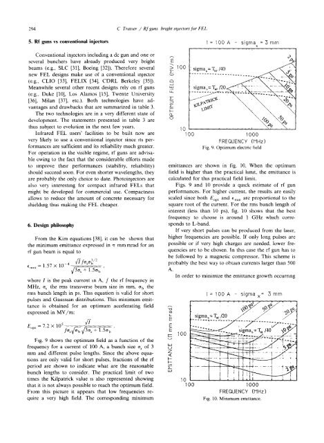
I = 100 A - sigma . . = 3 mm<br />
10<br />
100 1000<br />
FREQUENCY (MHz)<br />
Fig . 9 . Optimum electric field<br />
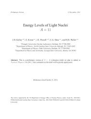
emittances are shown in fig. 10 . When the optimum<br />
field is higher than the practical limit, the emittance is<br />
calculated <strong>for</strong> this practical field limit .<br />
Figs . 9 and 10 provide a quick estimate of rf gun<br />
per<strong>for</strong>mances . For higher current, the results are easily<br />
scaled since both E.Pt and f r , are proportional to the<br />
square root of the current. For the rms bunch length of<br />
interest (less than 10 ps), fig . 10 shows that the best<br />
frequency to choose is around 1 GHz which corresponds<br />
to L-band.<br />
If very short pulses can be produced from the laser,<br />
higher frequencies are possible . If only long pulses are<br />
possible or if very high charges are needed, lower frequencies<br />
are to be chosen . In this case the rf gun has to<br />
be followed by a magnetic compressor . This scheme is<br />
probably the best way to obtain currents larger than 500<br />
A.<br />
In order to minimize the emittance growth occurring<br />
I = 100 A - sigma x = 3 mm<br />
Eopt - 7.2 x 10 5 f7Y a b Sax_+ l .506<br />
Fig . 9 shows the optimum field as a function of the<br />
frequency <strong>for</strong> a current of 100 A, a bunch size ax of 3<br />
mm and different pulse lengths . Since the above equations<br />
are only valid <strong>for</strong> short pulses, fractions of the rf<br />
period are shown to indicate what are the reasonable<br />
bunch lengths to consider . The practical limit of two<br />
times the Kilpatrick value is also represented showing<br />
that it is not always possible to reach the optimum field.<br />
From this picture it appears that low frequencies require<br />
a very high field. The corresponding minimum<br />
E<br />
E<br />
C<br />
w<br />
U<br />
Z<br />
Q<br />
E-<br />
ui<br />
100<br />
10<br />
100 1000<br />
FREQUENCY (MHz)<br />
Fig . 10 . Minimum enuttance .

![TUNLXXXIV.tex typeset [1] - Triangle Universities Nuclear Laboratory](https://img.yumpu.com/47618358/1/190x245/tunlxxxivtex-typeset-1-triangle-universities-nuclear-laboratory.jpg?quality=85)