Rf guns: bright injectors for FEL - Triangle Universities Nuclear ...
Rf guns: bright injectors for FEL - Triangle Universities Nuclear ...
Rf guns: bright injectors for FEL - Triangle Universities Nuclear ...

Create successful ePaper yourself
Turn your PDF publications into a flip-book with our unique Google optimized e-Paper software.
<strong>Nuclear</strong> Instruments and Methods in Physics Research A304 (1991) 285-296 285<br />
North-Holland<br />
Section V .<br />
Accelerator technology<br />
<strong>Rf</strong> <strong>guns</strong> :<br />
<strong>bright</strong> <strong>injectors</strong> <strong>for</strong> <strong>FEL</strong><br />
C . Travier<br />
Laboratoire de !'Accélérateur Linéaire, IN2P3-CNRS and Université de Paris-sud, 91405 Orsay Cédex, France<br />
Invited paper<br />
Free electron lasers (<strong>FEL</strong>s) require very <strong>bright</strong> electron beams . During the past few years, rf <strong>guns</strong> have demonstrated their<br />
potentiality to produce such <strong>bright</strong> beams . A review of the on-going worldwide ef<strong>for</strong>t to develop this new technology is given . Present<br />
limitations and possible improvements are also presented . General design considerations are introduced .<br />
1 . Introduction<br />
<strong>FEL</strong>s require very good quality electron beams . A<br />
low emittance is necessary to obtain short wavelengths .<br />
A high peak current provides a good gain . These requirements<br />
are already met by the best conventional<br />
<strong>injectors</strong> (dc gun + buncher) <strong>for</strong> the infrared spectrum .<br />
However, a need <strong>for</strong> <strong>bright</strong>er beams is real to improve<br />
IR-<strong>FEL</strong> per<strong>for</strong>mances and to obtain shorter wavelength<br />
lasers . There<strong>for</strong>e, new ideas are necessary since conventional<br />
<strong>injectors</strong> have nearly reached their limits [1] .<br />
In 1983, Madey and Westenskow [2] proposed to put<br />
a thermionic cathode in an rf cavity. This new gun<br />
named "rf gun" or "microwave gun" was used as a<br />
<strong>bright</strong> electron source <strong>for</strong> the Mark III <strong>FEL</strong> . Meanwhile,<br />
Lee et al . [3] reported that very high current densities<br />
could be obtained from semiconductor photocathodes .<br />
Then, Fraser and Sheffield [4,5] experimented the use of<br />
such cathodes in an rf gun . The "first demonstration of<br />
a <strong>FEL</strong> driven by electrons from a laser irradiated photocathode"<br />
was made at Stan<strong>for</strong>d in 1988 [6] .<br />
Since that time, many laboratories have undertaken<br />
the necessary ef<strong>for</strong>t to design and build an rf gun, with<br />
or without a photocathode . Almost 30 projects are<br />
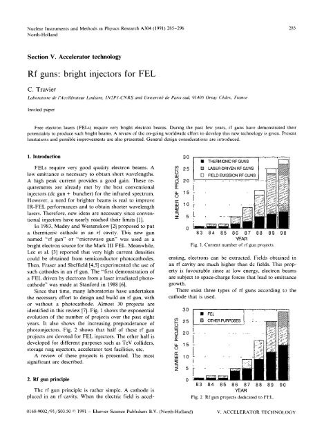
identified in this review [7] . Fig . 1 shows the exponential<br />
evolution of the number of projects over the past eight<br />
years . It also shows the increasing preponderance of<br />
photo<strong>injectors</strong> . Fig . 2 shows that half of these rf gun<br />
projects are devoted <strong>for</strong> <strong>FEL</strong> <strong>injectors</strong> . The other half is<br />
developed <strong>for</strong> different purposes such as TeV colliders,<br />
storage ring <strong>injectors</strong>, accelerator test facilities, etc.<br />
A review of these projects is presented . The most<br />
significant are described .<br />
2. <strong>Rf</strong> gun principle<br />
The rf gun principle is rather simple . A cathode is<br />
placed in an rf cavity . When the electric field is accel-<br />
cil<br />
U<br />
w<br />
ari<br />
0-<br />
U_<br />
O<br />
mwm<br />
z<br />
z<br />
30<br />
20<br />
15<br />
10<br />
5<br />
30<br />
25<br />
U<br />
w<br />
20 am<br />
a<br />
15<br />
O<br />
m<br />
w<br />
m<br />
10<br />
5<br />
N THERMIONIC RF GUNS<br />
25 ® LASER-DRIVEN RF GUNS<br />
El<br />
FIELD EMISSION RF GUNS<br />
83 84 85 86 87 88 89 90<br />
YEAR<br />
Fig . 1 . Current number of rf gun projects .<br />
erating, electrons can be extracted . Fields obtained in<br />
an rf cavity are much higher than do fields . This property<br />
is favourable since at low energy, electron beams<br />
are subject to space-charge <strong>for</strong>ces that lead to emittance<br />
growth .<br />
There exist three types of rf <strong>guns</strong> according to the<br />
cathode that is used .<br />
83 84 85 86 87 88 89 90<br />
YEAR<br />
Fig . 2 <strong>Rf</strong> gun projects dedicated to <strong>FEL</strong> .<br />
0168-9002/91/$03 .50 © 1991 - Elsevier Science Publishers B.V . (North-Holland)<br />
V . ACCELERATOR TECHNOLOGY
28 6 C Travier / <strong>Rf</strong> <strong>guns</strong> <strong>bright</strong> <strong>injectors</strong> <strong>for</strong> <strong>FEL</strong><br />
2.1 . Thermionic rf gun<br />
Electrons are continuously emitted by a thermionic<br />
cathode but can only be extracted and accelerated during<br />
half an rf cycle. The electrons, emitted during the<br />
accelerating half cycle, but with a too large phase (typically<br />
larger than 100') do not have enough energy to<br />
reach the cavity output and are accelerated backward to<br />
the cathode .<br />
The pulse that actually comes out the cavity is very<br />
long (about one fourth of the rf period) and has a very<br />
large energy spread . It is thus necessary to place behind<br />
the gun a magnetic bunching system (e .g ., an "a-magnet")<br />
with energy slits to reduce the pulse length, increase,the<br />
peak current and select a given spectrum .<br />
2 .2 . Laser-driven rf <strong>guns</strong><br />
A photocathode placed in an rf cavity is illuminated<br />
by a laser which delivers short pulses . There<strong>for</strong>e as they<br />
leave the cathode, electrons are already bunched .<br />
Besides the obvious advantages (high field, bunched<br />
beam), laser-driven <strong>guns</strong> have other attractive features .<br />
The pulse <strong>for</strong>mat is more flexible than that of conventional<br />
<strong>injectors</strong> and that of thermionic rf <strong>guns</strong>. It depends<br />
essentially on the laser pulse <strong>for</strong>mat which can be<br />
varied over a wide range. Photocathodes can deliver<br />
much higher current densities than thermionic cathodes :<br />
more than 400 A/cm2 has been reported [3] .<br />
2 .3 Field emission rf <strong>guns</strong><br />
When placed in a high field, sharp needles can<br />
produce electrons by the so-called field emission process<br />
. This principle can be used in an rf gun . The<br />
difficulty is to find stable operating conditions . When<br />
high current is emitted, the needle is heated and easily<br />
destroyed .<br />
3 . Worldwide review<br />
Since 1983, many laboratories have launched R&D<br />
programs on rf <strong>guns</strong> . Some are already producing experimental<br />
results while others are still at the preliminary<br />
design stage. Reviewing all these projects is a<br />
difficult task, due to the fast changing situation and the<br />
lack of literature <strong>for</strong> the most recent projects . Thus, the<br />
review presented here is probably incomplete and <strong>for</strong><br />
some cases not up-to-date . May those who will not find<br />
their work reported here or who will find it reported<br />
inaccurately, be comprehensive and believe that they<br />
are not the subject of a special "censure" . Another<br />
difficulty met during this review was to produce consistent<br />
lists of parametersmorder to fairly compare the<br />
different projects . Each author uses his own units and<br />
definitions of the parameters and often all the parameters<br />
are not given <strong>for</strong> the same operating conditions .<br />
The following conventions are assumed . Design data<br />
<strong>for</strong> emittance are always given as four times the rms<br />
normalized emittance . When an author uses a different<br />
definition, necessary adjustments are made . Experimental<br />
data are reported as given in the publications . Since<br />
in some cases real beams have much longer tails than<br />
ideal beams and have not necessarily Gaussian or uni<strong>for</strong>m<br />
profile, the "4 rms" emittance may not be appropriate<br />
to describe them .<br />
For laser-driven <strong>guns</strong>, the rmcropulse length is taken<br />
as 4a b , where ab is the rms bunch length . Rms definition<br />
(lab) is adopted <strong>for</strong> thermionic <strong>guns</strong> because of the<br />
pulse shape which has a long tail and a very sharp front<br />
end . In this case, la b includes most of the particles .<br />
When only the charge Q and the bunch length T are<br />
given, the peak current I is calculated in a conservative<br />
way assuring a uni<strong>for</strong>m distribution (I = Q/T ) .<br />
Table 1 lists the different projects <strong>for</strong> each type of rf<br />
gun . Status of the projects and their main purpose are<br />
given . In table 2, the main parameters of each project<br />
are given . According to the project status, these parameters<br />
correspond to experimental or design values . A<br />
more detailed description of each project can be found<br />
in ref. [1] .<br />
3.1 . Stan<strong>for</strong>d (HEPL) - Duke (D<strong>FEL</strong>L)<br />
The first thermionic rf gun was built at Stan<strong>for</strong>d<br />
High Energy Physics Laboratory (HEPL) by Westenskow<br />
and Madey [2] to serve as an injector <strong>for</strong> the Mark<br />
III accelerator dedicated to <strong>FEL</strong> studies . The design<br />
work started in 1983 . The whole system (rf gun + lmac<br />
+ wiggler) was operated as a laser oscillator in September<br />
1985 . The system was then disassembled and moved<br />
to the Stan<strong>for</strong>d Photon Research Laboratory where it<br />
was lasing again in September 1986 . In August 1987, a<br />
new momentum filter which increased the peak current<br />
was installed . In September 1988, a new gun cavity<br />
allowed a more stable operation with longer rf macropulses<br />
(8 Ws) repeated at a higher frequency (15 Hz) .<br />
The thermionic gun consists of a LaB6 cathode placed<br />
in an rf cavity operated at 2857 MHz . The cavity is<br />
followed by a transport system including an "a-magnet"<br />
with momentum filter and several quadrupoles, as shown<br />
in fig. 3 . In order to control the backbombardment, a<br />
transverse magnetic field at the cathode was added [8] .<br />
A summary of the gun's main parameters and per<strong>for</strong>mances<br />
is given in table 2 [9] . After the "ci-magnet", 2<br />
to 3 ps electron pulses corresponding to 20 to 40 A peak<br />
current are obtained with emittances as good as 41T<br />
mm mrad in the vertical plane .<br />
In collaboration with Rocketdyne division of<br />
Rockwell Corporation, the same gun was operated as a
C. Trainer / <strong>Rf</strong> <strong>guns</strong> - <strong>bright</strong> <strong>injectors</strong> <strong>for</strong> <strong>FEL</strong> 28 7<br />
photoinjector and led in November 1988 to the first<br />
successful operation of a photoinjector driven <strong>FEL</strong> [6] .<br />
The LaB6 cathode was illuminated by a tripled<br />
Nd : YAG laser. Because the laser pulse was quite long<br />
(100 ps), the "a-magnet" was still necessary. Although<br />
the experiment was run <strong>for</strong> only a very short time, this<br />
photoinjector gave better results (in terms of current<br />
and emittance) than the thermionic gun [10] . The <strong>FEL</strong><br />
per<strong>for</strong>mances suggest rms emittances as good as 2m<br />
mm mrad in the vertical plane . The parameters and<br />
per<strong>for</strong>mances are given in table 2 [9] .<br />
The whole system was then disassembled again in<br />
December 1988 to be moved to Duke University Free<br />
Electron Laser Laboratory (D<strong>FEL</strong>L) where it was<br />
scheduled to be operating again in 1990 .<br />
3.2. Los Alamos National Laboratory<br />
Since at least 1984, Los Alamos National Laboratory<br />
(LANL) is involved in R&D programs about laserdriven<br />
rf <strong>guns</strong> and related topics like lasertron .<br />
In 1985, Lee et al . [3] demonstrated the possibility of<br />
extracting high current density (over 200 A/cm2) from<br />
CS 3 Sb photocathode illuminated by a frequency doubled<br />
Nd : glass laser. The first rf gun design consisted of<br />
one cavity operating at 1 .3 GHz and incorporating a<br />
Table 1<br />
List of rf gun projects<br />
Laboratory Country Status Beginning Beginning Purpose<br />
September 90 of design of tests<br />
Therauonic rf <strong>guns</strong><br />
Stan<strong>for</strong>d - Duke [2,10] USA tested 1983 2/85 <strong>FEL</strong><br />
IHEP Bering [451 China tested 6/86 2/88 <strong>FEL</strong><br />
Mitsubishi [461 Japan tested<br />
IPT Kharkov [47] USSR tested ? storage ring injector<br />
AET/Varian/SSRL [431 USA under tests 1988? 1989 storage ring injector<br />
KEK [48] Japan construction 1989 1989 <strong>FEL</strong>/other<br />
North Carolina Central USA construction ? 1991 microwave<br />
University (NCCU) [49]<br />
generator<br />
Stan<strong>for</strong>d University [50] USA design 1990 ? <strong>FEL</strong><br />
Laser-driven rf <strong>guns</strong><br />
Los Alamos [12] USA tested/stopped 1984? 1985 rf gun<br />
Los Alamos (HIBAF) [24] USA operating 9/88 5/89 <strong>FEL</strong><br />
Stan<strong>for</strong>d -> Duke [6] USA tested 1987? 9/88 <strong>FEL</strong><br />
CEA [17,19] France under tests 3/86 1989 <strong>FEL</strong><br />
Brookhaven [20,21] USA under tests 1987? 1989 new accelerator<br />
methods/<strong>FEL</strong><br />
CERN [511 Switzerland rf tests 1988? 1990 collider<br />
Argonne [52] USA construction 1988 ? wakefield accelerator<br />
Wuppertal [53] Germany construction 1987? ? <strong>bright</strong> injector<br />
Twente [36] Netherlands construction ? ? <strong>FEL</strong><br />
Duke [9] USA construction 9/89 6/91 storage ring injector<br />
Boeing [54] USA construction ? ? <strong>FEL</strong><br />
Rockwell [55] USA construction ? ? <strong>FEL</strong><br />
Los Alamos (A<strong>FEL</strong>) [151 USA design 1988? ? <strong>FEL</strong><br />
INFN Milan [37] Italy design 1988? ? <strong>FEL</strong><br />
LAL Orsay [56] France design 9/89 1991 rf gun<br />
INFN Frascati [57] Italy design ? 9 <strong>FEL</strong><br />
MIT [58] USA design 1990 ? collider<br />
KEK [591 Japan design ? ? collider<br />
UCLA [601 USA ? ? ° <strong>FEL</strong><br />
Vanderbilt University [9] USA ? ? ? <strong>FEL</strong><br />
LLNL/SLAC/LBL [611 USA stopped 1987 - high gradient<br />
accelerator<br />
Field emission rf <strong>guns</strong><br />
IHEP Beijing [62] China preliminary design 1988? ? <strong>FEL</strong><br />
LAL Orsay [63] France stopped 1988 1/89 rf gun<br />
V ACCELERATOR TECHNOLOGY
I<br />
I<br />
I<br />
288<br />
C. Travier / <strong>Rf</strong> <strong>guns</strong> <strong>bright</strong> <strong>injectors</strong> <strong>for</strong> <strong>FEL</strong><br />
L<br />
C<br />
o<br />
¢ O d r r. v O O O O r,<br />
N n r N O<br />
, M v<br />
z<br />
M C O O M<br />
N .-1 O N<br />
N M O<br />
.,4 r-1<br />
w<br />
Q u.<br />
M<br />
L'<br />
z<br />
u .<br />
LU<br />
w z<br />
Y N<br />
h<br />
b<br />
c<br />
~<br />
O<br />
'e<br />
O 00<br />
N<br />
= M r- CD O N<br />
CD<br />
~o<br />
ô<br />
a<br />
I ~ ô , °oM I ~ I T ° I ° I ô<br />
U<br />
N<br />
00<br />
w<br />
n. ., N<br />
o<br />
¢ b<br />
n<br />
x<br />
Jz<br />
.o "n ~ _ 1<br />
,ô'o o° 10<br />
V' ï O ~ ^ N Qj N<br />
U<br />
O<br />
i o,- .<br />
T OI<br />
~O V `°<br />
O<br />
r^ r<br />
N N<br />
°° O<br />
M<br />
c<br />
V<br />
z<br />
M<br />
U<br />
ro<br />
s z<br />
a<br />
F<br />
-<br />
y<br />
U<br />
O p~<br />
N CD W 1<br />
.. v~<br />
M<br />
N M N o0 O `o<br />
y O O N O<br />
T -<br />
G<br />
¢ y b<br />
ô z<br />
a a<br />
Or - r, ô O V M<br />
U<br />
M<br />
w<br />
x<br />
I I I I<br />
Ç<br />
-a X<br />
bn<br />
C<br />
ro<br />
ro<br />
N U<br />
o a .<br />
o ~<br />
ô<br />
â. â ><br />
N c 4 3 aq b Â<br />
â0<br />
y v ti C<br />
cN7 c~d<br />
F â aa z<br />
r<br />
o~o V I V<br />
N<br />
C V N I I I ~ I N<br />
I I I<br />
ti .<br />
I I I<br />
I E N O 0 O<br />
N<br />
ri<br />
C N I N "P , ', O<br />
P . O N V<br />
cG<br />
O ti<br />
N N O i C ro<br />
b<br />
V4<br />
T<br />
O<br />
r- O<br />
ô<br />
O v~ o`<br />
C~ U<br />
O CD<br />
O N O Vl<br />
ON<br />
0ẇ<br />
GO<br />
n -7<br />
~<br />
rn N r VI `n M<br />
X co O G w<br />
N<br />
on<br />
C<br />
oa<br />
I I I<br />
N<br />
O<br />
ti c- 1) O ~ O O<br />
0o ~ oo M<br />
.-1 X N<br />
C N ti<br />
V N<br />
77- O ,<br />
ô ~ O<br />
r O M<br />
J<br />
i<br />
O<br />
X<br />
r<br />
',<br />
N<br />
O Ô<br />
O<br />
C<br />
.,.<br />
r<br />
O in V1 M<br />
O O N I 00 N ,<br />
N<br />
êê~<br />
N x<br />
x 2 5:7<br />
N y<br />
> 57 P .<br />
X_<br />
c C<br />
~<br />
U C on Q , W ?<br />
ro v b<br />
U "9)<br />
C ~ ? b il.<br />
O U pp °: , .. a) ro ti A<br />
T cxd cd<br />
ti U y d E \<br />
U<br />
C C ~<br />
3 al 7 ,^ `C U ¢<br />
o ° . °,<br />
b 0<br />
a a<br />
o<br />
ono 0<br />
cod9<br />
cXd c~C<br />
cUC C V ~ ~ 8 ~o<br />
N cG . p ~ ~ Ô û<br />
~<br />
M<br />
W K<br />
x CL<br />
3<br />
w W<br />
ro ro<br />
"0 "a<br />
v O<br />
OV M r N N<br />
lm "Z~<br />
G<br />
C<br />
Û<br />
I<br />
O ~ :d<br />
U<br />
w<br />
cC<br />
â<br />
3<br />
.D<br />
U ~ .<br />
N > Û ti N b<br />
id Û .>.. .>., C C .~ C<br />
N . . N ~ y<br />
a C<br />
~Q~xxâ~3~~
C Travier / <strong>Rf</strong> <strong>guns</strong> .- <strong>bright</strong> <strong>injectors</strong> <strong>for</strong> <strong>FEL</strong><br />
289<br />
v 0 ,::,<br />
-Z<br />
LL,<br />
- .0 0 °° 0 "T " 1 0<br />
~. ~i - In<br />
4D r, Do - 0 ~)<br />
z<br />
8<br />
't<br />
C5<br />
w 2<br />
Am h<br />
0<br />
1<br />
00<br />
'1:1 Q) CA<br />
C4<br />
N "1 2 2 o : N<br />
cl 6 "'~ 'r ~! , " N<br />
wl<br />
u2<br />
00<br />
S<br />
I f `Q CA M 06 1<br />
0<br />
u<br />
0+ opo<br />
ON ri<br />
z<br />
v<br />
oOq<br />
0<br />
2<br />
1<br />
0<br />
v ,-, a} .<br />
S . ,<br />
,-r a 5 05. 6<br />
0 n<br />
0<br />
CD<br />
z<br />
w<br />
u<br />
10<br />
C,400 00 0 0 t-<br />
6<br />
z"<br />
n<br />
0<br />
Z~<br />
> > ", -Z ;, - g<br />
~~ ~ > ~~ u > Or . Q<br />
0J I s! 7 :2 -0 - -ts " ~<br />
0<br />
0 - 0 '53 ~~ ~2- , ?, ':3 -M<br />
:L Z - ' E x " - ;~ -~ ~ v ,<br />
a 0 m 42<br />
-<br />
lu<br />
y Ci<br />
'0<br />
10<br />
.o * 1 y . 2 E) = 0 , m *6 a,- 0,-,2 u *0 0,<br />
0<br />
il 11 C -r- -I- 0 '1 m ~9 - r- It ~ 2<br />
"t 0 â<br />
.2<br />
C-) u z<br />
LZ ~5 ~- ~ 2 S2 :5<br />
t 10<br />
E - ;~ - a' -<br />
- . ".0 97 .0 'E<br />
E ~<br />
~ ~ E ,<br />
m 0<br />
't lu<br />
E . E 0=~ -C~<br />
Ai 0<br />
z 04 z<br />
-<br />
I<br />
'.<br />
E U -,d<br />
-,, r<br />
~ :3 Z! 0<br />
Nw<br />
g<br />
u e E<br />
= "<br />
-M .6 . 0 V 4)<br />
CL CLI 0. 2<br />
~ - 11 w V110,<br />
- - 9 C G<br />
V. ACCELERATOR TECHNOLOGY
290<br />
C. Tracter / <strong>Rf</strong> <strong>guns</strong>- <strong>bright</strong> <strong>injectors</strong><strong>for</strong> <strong>FEL</strong><br />
T<br />
QUADRUPOLE<br />
VERTICAL STEERING<br />
-i `- HORIZONTAL STEERING<br />
Fig. 3 . Stan<strong>for</strong>d/Duk e rf gun layout (from ref. [44]) .<br />
Cs 3Sb photocathode illuminated by a frequency doubled<br />
Nd : YAG laser [4] .<br />
The cavity shape was designed to minimize the nonlinear<br />
components of the radial electric field, assuming<br />
a do approximation . This gun produced a 1 MeV beam<br />
of 70 ps pulses with a peak current of 200 A and a<br />
normalized enuttance of 40m mmmrad [I1].<br />
A second cavity independently powered and phased<br />
was then added to the original one . Meanwhile, the<br />
adjunction of a pulse compressor to the laser allowed to<br />
generate 16 ps optical pulses . This new gun tested in<br />
1987 and 1988, provided a 2.7 MeV beam . The maximum<br />
extracted charge was 13 .2 nC corresponding to a<br />
peak current of 600 A. No enuttance measurements<br />
were possible due to the drift space between the second<br />
cavity and the "pepper-pot" device that led to excessive<br />
space-charge emittance growth [12] .<br />
During this period, the photocathode lifetime was<br />
significantly improved by replacing Cs 3Sb with CsK 2 Sb .<br />
This lifetime remained very dependent though on the<br />
operating conditions . Table 2 summarizes the per<strong>for</strong>mances<br />
of the two experiments named <strong>for</strong> convenience<br />
phase I and phase 11 .<br />
Based on the gained experience, a new photoinlector<br />
was built to serve as an electron source <strong>for</strong> the HIBAF<br />
infrared <strong>FEL</strong> [13] . This new gun which replaced the<br />
previous conventional injector provides a 350 A, 16 ps<br />
and 351T mm mrad beam. It consists of six cells where<br />
the first cell contains the CsK 2Sb photocathode (fig . 4) .<br />
This photoinlector has been designed <strong>for</strong> maximum<br />
flexibility in order to do parametrization studies <strong>for</strong><br />
LOS ALAMOS NATIONAL LABORATORY<br />
ACCELERATOR TECHNOLOGY DIVISION<br />
GROI.P AT-1<br />
1300 Mi; PHOTOINJECTOR LINAC<br />
Fig . 4 . Los Alamos HIBAF rf gun (from ref . [14]) .
C. Travier / <strong>Rf</strong> <strong>guns</strong> : <strong>bright</strong> <strong>injectors</strong> <strong>for</strong> <strong>FEL</strong><br />
291<br />
Fig. 5 . CEA photoinjector (from ref . [19]).<br />
simulation codes verification . Nominal per<strong>for</strong>mances<br />
are given in table 2 [14].<br />
Because of the possible industrial use of <strong>FEL</strong>, it is<br />
interesting to develop a very compact device. This work<br />
has been undertaken by LANL [15] . A compact <strong>FEL</strong><br />
named A<strong>FEL</strong> is now under design . The photoinjector<br />
will consist of ten cells powered by one rf source. All<br />
flexibility will be removed and the parameters will be<br />
chosen <strong>for</strong> an optimum design according to simulations .<br />
This injector should be able to produce a beam <strong>bright</strong>ness<br />
of the order of 10 12 A/(m2 rad 2 ) (table 2) .<br />
Carlsten proposed a very powerful way to reduce the<br />
emittance of a photoinjector [161 . After identifying the<br />
four different emittance growth mechanisms : (a) linear<br />
space charge, (b) nonlinear space charge, (c) nonlinear<br />
time-independent rf effect, (d) linear time-dependent rf<br />
effect, he shows that <strong>for</strong> a pulse produced by a laser, it<br />
is possible to remove most of the correlated emittance<br />
(variations in the transverse phase space correlated with<br />
longitudinal position) by a proper choice of position<br />
and strength of magnetic lenses . Such a theory is not<br />
applicable <strong>for</strong> conventional <strong>injectors</strong> since bunching<br />
~F TUNER<br />
Fig . 6 . BNL rf gun cavity (from ref. [21]).<br />
V ACCELERATOR TECHNOLOGY
292<br />
C Travier / <strong>Rf</strong> <strong>guns</strong>: <strong>bright</strong> <strong>injectors</strong> <strong>for</strong> <strong>FEL</strong><br />
introduces mixing between longitudinal and transverse<br />
phase-space planes . A<strong>FEL</strong> design is based on this theory<br />
.<br />
3 3. CEA Bruyères-le-Châtel<br />
The Commissariat à l'Energie Atomique (CEA) in<br />
Bruy6res-le-Châtel (France) has built a laser-driven rf<br />
gun as an injector <strong>for</strong> a high-power infrared <strong>FEL</strong> [17] .<br />
In order to improve the beam characteristics, a frequency<br />
of 433 MHz was chosen <strong>for</strong> the linac and a subharmonic<br />
frequency of 144 MHz <strong>for</strong> the gun . At first,<br />
one cavity is used providing a 1 MeV beam (fig . 5) .<br />
Later, a second cavity will be added . Cs 3Sb and CsK,Sb<br />
photocathodes are used . Other types are also tested . The<br />
goal is to produce a 50-100 ps, 10-20 nC beam pulse .<br />
Design parameters [18] are summarized in table 2 . This<br />
gun is now under testing . An accelerating field of 25<br />
MV/m on the cathode has been obtained . 20 nC, 100<br />
ps pulses have been accelerated to 1 MeV . An emittance<br />
of 901T mmmrad was measured <strong>for</strong> a 10 nC pulse [191 .<br />
3 .4 . Brookhaven National Laboratory<br />
.<br />
In order to study several ideas related to future<br />
particle acceleration methods, Brookhaven National<br />
Laboratory (BNL) is building an accelerator test facility<br />
(ATF) [20] which will also be used <strong>for</strong> <strong>FEL</strong> physics . The<br />
injector <strong>for</strong> the accelerator is a laser-driven rf gun<br />
operating at 2856 MHz. It consists of a one and a half<br />
cell cavity incorporating a photocathode in the end wall<br />
of the first cell . The cavity shape was designed so that rf<br />
fields cause minimal nonlinear distortion of the phase<br />
spaces (fig . 6) . This was obtained by using a Fourier<br />
decomposition of the rf fields and by setting the radial<br />
field to be linear [21] .<br />
The gun is designed to operate with a 100 MV/m<br />
electric field at cathode. The laser will provide a 4 to 6<br />
ps pulse . 1 nC is expected from the yttrium photocathode<br />
The main design parameters are shown in table<br />
2 . The gun has already been tested with a 20 ns pulse<br />
from an excimer laser . A 90 MV/m accelerating field<br />
was obtained at the cathode . A peak current of 0.6 A<br />
was accelerated to 3.6 MeV [20] . The picosecond<br />
Nd : YAG laser is now available and experiments will<br />
proceed soon .<br />
Meanwhile, extensive studies of metallic photocathodes<br />
are done [22] .<br />
10 4 "<br />
~ M LASER-DRIVEN GUNS EXPERIMEN-AL RESU_TS<br />
-ASER-DRIVEN GUNS DESIGN<br />
PARAhETEPS<br />
HERMIONIC GJNS EX~EPir'ENTAL PARAMEIERS<br />
the <strong>bright</strong>ness as a function of the peak current and the<br />
bunch length respectively, <strong>for</strong> the different rf gun projects.<br />
These figures are only indicative and should be considered<br />
with some care . Fig . 7 also shows the <strong>bright</strong>ness<br />
corresponding to different wavelength <strong>FEL</strong> . From these<br />
figures a few general comments can be made. Both<br />
thermionic and laser driven rf <strong>guns</strong> have demonstrated<br />
their capability to produce very <strong>bright</strong> beams (roughly<br />
one order of magnitude higher than conventional <strong>injectors</strong>)<br />
. Thermionic rf <strong>guns</strong> provide smaller peak currents<br />
than photoinlectors . The best laser-driven rf gun should<br />
be sufficient to reach wavelengths m the XUV domain<br />
provided that suitable wigglers can be built <strong>for</strong> such<br />
short wavelengths . X-ray domain is out of reach <strong>for</strong> the<br />
current state of the art .<br />
E<br />
Q<br />
cn<br />
cn<br />
w<br />
z<br />
10' 4<br />
10 12<br />
10 100 1000 10000<br />
CURRENT (A)<br />
Fig. 7 <strong>Rf</strong> gun <strong>bright</strong>ness vs peak current .<br />
LASER-DRIVEN GUNS EXPERIMENTAL RESU-IS<br />
O LASER-D-2IVEN GUNS DESIGN PARAMETERS<br />
'HER - 1ONIC GUNS EXPERIMENTAL PARA - E - ERS<br />
4 . State of the art<br />
A figure of merit of the beam quality can be the<br />
peak <strong>bright</strong>ness defined here as two times the peak<br />
current divided by the square of the normalized emittance<br />
. It is expressed in A/(m 2 rad2 ) . Figs . 7 and 8 show<br />
ro<br />
10<br />
1 10 100 1000<br />
BUNCH LENGTH (PS)<br />
Fig . 8 . <strong>Rf</strong> gun <strong>bright</strong>ness vs bunch length
C Tracter / <strong>Rf</strong> <strong>guns</strong> <strong>bright</strong> <strong>injectors</strong> <strong>for</strong> <strong>FEL</strong><br />
293<br />
What are the present limitations in rf gun technology?<br />
As mentioned earlier, thermionic rf <strong>guns</strong> suffer from<br />
the backbombardment problem. The extra heat due to<br />
the backbombarded electrons increases the peak current<br />
during the rf macropulse which is not good <strong>for</strong> <strong>FEL</strong><br />
operation. It also limits the duty cycle . Adding a transverse<br />
magnetic field improves the situation since the<br />
most energetic electrons come back on the cavity wall<br />
beside the cathode . Using this technique, Stan<strong>for</strong>d could<br />
obtain a 10 ps macropulse repeated at 15 Hz without<br />
current increase during the macropulse [10) . If more<br />
current and higher duty cycles are needed, the backbombardment<br />
problem will still be a limitation .<br />
Conventional thertmonic cathodes have current densities<br />
of a few tens of A/cm2 . Recently, however, more<br />
than 100 A/cm 2 has been reported [23] . These values<br />
are nevertheless much smaller than that reported <strong>for</strong><br />
photocathodes.<br />
Since in a thermionic rf gun, every rf bucket is filled,<br />
the beam loading is very important . Reflected electrons<br />
and secondary electrons also participate to beam loading<br />
. At equivalent peak current, thermionic rf <strong>guns</strong><br />
require more rf power than laser-driven rf <strong>guns</strong> . This<br />
fact could be a limitation <strong>for</strong> high currents .<br />
Photo<strong>injectors</strong> rely on photocathodes and laser technology .<br />
The optimum photocathode (good quantum efficiency,<br />
long lifetime, good ability to withstand high<br />
fields) has not yet been found . The most successful<br />
photocathodes mainly studied at Los Alamos (Cs3Sb,<br />
CsK2Sb) have a very good quantum efficiency (2 to<br />
8%) . Their lifetime depends on the operating conditions .<br />
For their typical operating conditions (200 times 5 nC<br />
micropulses repeated at 1 Hz, 2 x 10⁻⁹ Torr pressure),<br />
Los Alamos HIBAF photocathodes have a 15 h lifetime<br />
[24), the production time <strong>for</strong> one cathode being 3 h . In<br />
order to improve this lifetime, Sheffield suggested to use<br />
a glow discharge to clean the cavity prior to its operation<br />
[251 .<br />
The main alternative to these multi-alkaline photocathodes<br />
are the thermionic cathodes (dispenser, LaB6 )<br />
and the metallic cathodes . They both have a lower<br />
quantum efficiency and are more robust . Only LaB6 has<br />
been seriously tested in an rf gun [6). Dispenser cathodes<br />
are now studied in a do gun at Orsay [261.<br />
Metallic cathodes have been extensively studied at<br />
BNL both in picosecond and femtosecond regimes<br />
[27,28] in a do configuration . Quantum efficiency as<br />
high as 7.25 x 10⁻⁴ has been measured <strong>for</strong> samarium<br />
photocathodes . A current of 21 kA/cm2 has been extracted<br />
from a 7 mm2 yttrium photocathode . This result<br />
corresponds to the "highest current density reported to<br />
date <strong>for</strong> a macroscopic photoemitter" . These photocathodes<br />
have now to be tested in an rf gun configuration<br />
.<br />
Several other photocathode studies are currently un-<br />
.<br />
.<br />
der way in many different laboratories . A good overview<br />
can be found in ref. [29) .<br />
An important issue <strong>for</strong> any type of photocathode is<br />
the dark current (current due to field emission) . This<br />
current depends on the photocathode material and the<br />
field level in the cavity At Los Alamos, <strong>for</strong> the operating<br />
conditions mentioned above, a current of 100 fC per<br />
rf cycle was measured [301 . In case of cw operation, this<br />
dark current could carry a significant power .<br />
The laser used to illuminate the photocathode should<br />
provide very short pulses, at the wavelength corresponding<br />
to the photocathode spectral response . Given the<br />
photocathode quantum yield, the laser macropulse<br />
should carry enough energy to extract the desired charge .<br />
The laser should be synchronized to the rf, i .e . the laser<br />
micropulse should correspond to a determined phase of<br />
the rf signal . This phase should be repeated from pulse<br />
to pulse with a timing jitter much less than the pulse<br />
length The laser micropulse should be as uni<strong>for</strong>m as<br />
possible in both transverse and longitudinal directions .<br />
Uni<strong>for</strong>m trains of micropulses are required at a repetition<br />
rate that varies from a few tens of MHz <strong>for</strong> <strong>FEL</strong><br />
to a few GHz <strong>for</strong> linear colliders' driving beams .<br />
Over the last few years, lasers suitable <strong>for</strong> rf gun<br />
operation have been developed . A lot more work is<br />
required to improve some of the per<strong>for</strong>mances and<br />
bring them to a high level of reliability . The most<br />
critical issues are the uni<strong>for</strong>m pulse shape, the phase<br />
and amplitude stability and the very high micropulse<br />
repetition rate especially when very short energetic<br />
pulses are required. The typical present per<strong>for</strong>mances<br />
are :<br />
micropulse length 10-20 ps,<br />
micropulse energy 10-100 pJ,<br />
repetition rate 20-100 MHz,<br />
amplitude jitter 1%,<br />
timing jitter 1-2 ps .<br />
Table 3<br />
Comparison of rf gun vs conventional <strong>injectors</strong><br />
Conventional<br />
injector<br />
<strong>Rf</strong> gun<br />
thermionic laser-driven<br />
High accelerating field - + +<br />
Current density<br />
Short pulse<br />
-<br />
-<br />
-<br />
-<br />
+<br />
+<br />
Pulse <strong>for</strong>mat flexibility - - +<br />
Cathode lifetime + + -<br />
<strong>Rf</strong> system simplicity - + +<br />
Compactness - - +<br />
Timmgjitter + +<br />
Energy fitter + +<br />
Development state + -<br />
Cost<br />
V. ACCELERATOR TECHNOLOGY
294<br />
C Traoier / <strong>Rf</strong> <strong>guns</strong> <strong>bright</strong> <strong>injectors</strong> <strong>for</strong> <strong>FEL</strong><br />
5 . <strong>Rf</strong> <strong>guns</strong> vs conventional <strong>injectors</strong><br />
Conventional <strong>injectors</strong> including a do gun and one or<br />
several bunchers have already produced very <strong>bright</strong><br />
beams (e .g., SLC [31], Boeing [32]) . There<strong>for</strong>e several<br />
new <strong>FEL</strong> designs make use of a conventional injector<br />
(e .g ., CLIO [33], <strong>FEL</strong>IX [34], CDRL Berkeley [35]) .<br />
Meanwhile several other recent designs rely on rf <strong>guns</strong><br />
(e.g ., Duke [10], Los Alamos [15], Twente University<br />
[361, Milan [37], etc .) . Both technologies have advantages<br />
and drawbacks that are summarized in table 3 .<br />
The two technologies are in a very different state of<br />
development . The statements presented in table 3 are<br />
thus subject to evolution in the next few years .<br />
Infrared <strong>FEL</strong> users' facilities to be built now are<br />
very likely to use a conventional injector since its per<strong>for</strong>mances<br />
are sufficient and its reliability much greater .<br />
For operation in the visible regime, rf <strong>guns</strong> are advisable<br />
owing to the fact that the considerable ef<strong>for</strong>ts made<br />
to improve their per<strong>for</strong>mances (stability, reliability)<br />
should succeed soon . For even shorter wavelengths, they<br />
are probably the only choice to date . Pboto<strong>injectors</strong> are<br />
also very interesting <strong>for</strong> compact infrared <strong>FEL</strong>s that<br />
might be developed <strong>for</strong> commercial use . Compactness<br />
allows to reduce the amount of concrete necessary <strong>for</strong><br />
shielding thus making the <strong>FEL</strong> cheaper.<br />
6 . Design philosophy<br />
From the Kim equations [38], it can be shown that<br />
the minimum emittance expressed in iT mm mrad <strong>for</strong> an<br />
rf gun beam is equal to<br />
e<br />
mm<br />
- 1 .57 X 10-_<br />
~faxa6~2<br />
where I is the peak current to A, f the rf frequency in<br />
MHz, a, the rms transverse beam size in mm, a b the<br />
rms bunch length in ps . This equation is valid <strong>for</strong> short<br />
pulses and Gaussian distributions, This minimum emittance<br />
is obtained <strong>for</strong> an optimum accelerating field<br />
expressed in MV/m :<br />
0<br />
_J<br />
w<br />
w<br />
0<br />
I = 100 A - sigma . . = 3 mm<br />
10<br />
100 1000<br />
FREQUENCY (MHz)<br />
Fig . 9 . Optimum electric field<br />
emittances are shown in fig. 10 . When the optimum<br />
field is higher than the practical limit, the emittance is<br />
calculated <strong>for</strong> this practical field limit .<br />
Figs . 9 and 10 provide a quick estimate of rf gun<br />
per<strong>for</strong>mances . For higher current, the results are easily<br />
scaled since both E.Pt and f r , are proportional to the<br />
square root of the current. For the rms bunch length of<br />
interest (less than 10 ps), fig . 10 shows that the best<br />
frequency to choose is around 1 GHz which corresponds<br />
to L-band.<br />
If very short pulses can be produced from the laser,<br />
higher frequencies are possible . If only long pulses are<br />
possible or if very high charges are needed, lower frequencies<br />
are to be chosen . In this case the rf gun has to<br />
be followed by a magnetic compressor . This scheme is<br />
probably the best way to obtain currents larger than 500<br />
A.<br />
In order to minimize the emittance growth occurring<br />
I = 100 A - sigma x = 3 mm<br />
Eopt - 7.2 x 10 5 f7Y a b Sax_+ l .506<br />
Fig . 9 shows the optimum field as a function of the<br />
frequency <strong>for</strong> a current of 100 A, a bunch size ax of 3<br />
mm and different pulse lengths . Since the above equations<br />
are only valid <strong>for</strong> short pulses, fractions of the rf<br />
period are shown to indicate what are the reasonable<br />
bunch lengths to consider . The practical limit of two<br />
times the Kilpatrick value is also represented showing<br />
that it is not always possible to reach the optimum field.<br />
From this picture it appears that low frequencies require<br />
a very high field. The corresponding minimum<br />
E<br />
E<br />
C<br />
w<br />
U<br />
Z<br />
Q<br />
E-<br />
ui<br />
100<br />
10<br />
100 1000<br />
FREQUENCY (MHz)<br />
Fig . 10 . Minimum enuttance .
C. Traurer / <strong>Rf</strong> <strong>guns</strong> . <strong>bright</strong> <strong>injectors</strong><strong>for</strong> <strong>FEL</strong><br />
295<br />
during drifts at low energy, it is better to use several<br />
cells thus producing a beam with an energy larger than<br />
10 MeV at the end of the gun .<br />
The above equations did not include the use of a<br />
magnetic lens to reduce the emittance as suggested by<br />
Carlsten . However, Kim [39] showed that this method<br />
can be applied only if<br />
In yq < 1, arid 30 .7Ezr<br />
2<br />
where yq is the electron energy (m units of MC Z ) at the<br />
location of the lens, I is the peak current in A, E the<br />
gradient in MV/m and r the beam radius in mm .<br />
For<br />
typical values of current, beam radius and electric field,<br />
the above conditions show that emittance reduction due<br />
to the magnetic lens is only possible <strong>for</strong> low frequencies .<br />
Several other methods to reduce the emittance are<br />
being investigated such as laser pulse shaping [40]<br />
and<br />
time-dependent rf focusing [41,42] . Computer simulations<br />
show significant reduction of the beam emittance<br />
but the practicality of such methods is to be demonstrated<br />
. With these schemes, the residual emittance is<br />
mainly due to the thermal emittance of the cathode .<br />
7 . Conclusion<br />
Between 1983 and 1988, it was proven that thermionic<br />
and laser-driven rf <strong>guns</strong> could produce <strong>bright</strong><br />
electron beams. Starting in 1989, rf <strong>guns</strong> began to be<br />
widely studied and used in different laboratories .<br />
Ef<strong>for</strong>ts are made to push the technology to the limit<br />
while trying to improve its reliability . The first routine<br />
operation of an rf gun is starting at SSRL [43] .<br />
Starting in the fall of 1990, several laboratories will<br />
be ready to experiment their rf <strong>guns</strong> (CEA, BNL, CERN,<br />
DUKE, etc.) . It will then be possible to test the different<br />
types of cathodes in an accelerator environment .<br />
Long hours of operation experience will<br />
give birth to<br />
new ideas to bring the rf gun technology to a mature<br />
state .<br />
Acknowledgements<br />
I would like to thank very much J. Gao, H. Liu and<br />
B . Carlsten <strong>for</strong> helpful discussions . S.V . Benson, S.C .<br />
Chen, A. Enomo, G.J . Ernst, W. Gai, S. Joly, K.J . Kim,<br />
A. Michalke, R.L . Sheffield, Y. Tur and S . Zhong are<br />
acknowledged <strong>for</strong> providing me with a parameter list<br />
<strong>for</strong> their projects.<br />
Finally, I am indebted to J. Le Duff who gave me<br />
the opportunity to work on this subject .<br />
References<br />
.<br />
.<br />
.<br />
.<br />
.<br />
.<br />
C. Travier, Proc . ICFA Workshop on Short Pulse High<br />
Current Cathodes, Bendor, France, 1990 (Ed . Frontières)<br />
to be published .<br />
[21 G.A . Westenskow and J.M .J . Madey, Laser and Particle<br />
Beams 2 (1984) 223<br />
C.H Lee et al ., Proc. IEEE Particle Accelerator Conf<br />
Vancouver, Canada, 1985, IEEE Trans Nucl Sci . NS-32<br />
(5) (1985) 3045<br />
[4] J.S. Fraser et al ., ibid ., p 1791 .<br />
[51 R.L . Sheffield, E.R. Gray and J.S . Fraser, Nucl . Instr and<br />
Meth . A272 (1988) 222 .<br />
[6] M. Curtin et A., Proc. 11th Int. <strong>FEL</strong> Conf., Naples, FL,<br />
USA, 1989, Nucl . Instr and Meth . A296 (1990) 127 .<br />
[71 As known to the author by September 1990 .<br />
[8] C.B . McKee and J.MJ Madey, Proc. 11th Int. <strong>FEL</strong> conf .,<br />
Naples, FL, USA, 1989, Nucl. Instr. and Meth, A296<br />
(1990) 716 .<br />
S.V Benson, private communication .<br />
S.V . Benson et al ., Proc . 11th Int. <strong>FEL</strong> Conf., Naples, FL,<br />
USA, 1989, Nucl . Instr. and Meth . A296 (1990) 110.<br />
[11] J.S. Fraser et al ., Proc. IEEE Particle Accelerator Conf<br />
Washington, DC, USA, 1987, IEEE 87 CH2387-9, p .<br />
1705 .<br />
[12] R.L . Sheffield et al., Proc. Linear Accelerator Conf., Williamsburg,<br />
VA, USA, 1988, CEBAF-Report-89-001 (1989)<br />
P . 520 .<br />
[131 W.D . Cornelius et al ., Proc. 11th Int. <strong>FEL</strong> Conf ., Naples,<br />
FL, USA, 1989, Nucl . Instr . and Meth . A296 (1990) 251 .<br />
[14] D.W . Feldman et al ., these Proceedings (12th Int . <strong>FEL</strong><br />
Conf ., Pans, France, 1990) Nucl . Instr . and Meth . A304<br />
(1991) 224,<br />
R.L. Sheffield, private communication .<br />
[15] J.C . Goldstein et al ., Proc . 11th Int . <strong>FEL</strong> Conf., Naples,<br />
FL, USA, 1989, Nucl. Instr and Meth . A296 (1990) 282 .<br />
[16] B.E . Carlsten and R.L . Sheffield, Proc . Linear Accelerator<br />
Conf., Williamsburg, VA, USA, 1988, CEBAF-Report-89-<br />
001 (1989) p 365 .<br />
[17] R. Dei-Cas, Nucl Instr. and Meth . A285 (1989) 320<br />
[18] S . Joly, private communication .<br />
[19] R. Dei-Cas et al ., Proc . ICFA Workshop on Short Pulse<br />
.<br />
.<br />
.<br />
High Current Cathodes, Bendor, France, 1990 (Ed . Frontières)<br />
to be published.<br />
[20] K. Batchelor, Proc. Linear Accelerator Conf ., Albuquerque,<br />
NM, USA, 1990, to be published.<br />
[21] K.T . McDonald, Design of the Laser-Driven RF Electron<br />
Gun <strong>for</strong> the BNL Accelerator Test Facility, DOE/ER/<br />
3072-43 (Princeton University, 1988)<br />
[221 J. Fisher, Proc . ICFA Workshop on Short Pulse High<br />
Current Cathodes, Bendor, France, 1990 (Ed Frontières)<br />
to be published .<br />
[231 L. Falce, ibid ., to be published.<br />
[24] P.G. O'Shea et a] ., Proc . Linear Accelerator Conf. Albuquerque,<br />
NM, USA, 1990, to be published<br />
[251 R.L. Sheffield, ibid,<br />
[26] H. Bergeret, M. Boussoukaya, R. Chehab, B . Leblond and<br />
J. Le Duff, Proc . ICFA Workshop on Short Pulse High<br />
Current Cathodes, Bendor, France, 1990 (Ed Frontières)<br />
to be published .<br />
V. ACCELERATOR TECHNOLOGY
296<br />
C Travier / <strong>Rf</strong> <strong>guns</strong><br />
<strong>bright</strong> <strong>injectors</strong><strong>for</strong> <strong>FEL</strong><br />
. [27] T Srinivasan-Rae et al ., submitted to J Appl Phys.<br />
[28] T. Tsang et al , submitted to Phys . Rev . B<br />
[29] Proc ICFA Workshop on Short Pulse High Current<br />
Cathodes, Bender, France, 1990 (Ed . Frontières) to be<br />
published .<br />
[30] B . Carlsten, private communication .<br />
[31] M.B . James, Ph.D Dissertation, SLAC-319, UC-28 (A)<br />
(1987)<br />
[32] A. Yeremian et al ., Proc . Particle Accelerator Conf.,<br />
Chicago, IL, USA, 1989 IEEE Catalog no 89CH2669-0<br />
(1989)<br />
[33]<br />
[34]<br />
J.M Ortega et al ., Nue] . Instr. and Meth . A285 (1989) 97 .<br />
P.W Van Amersfoort et al., Proc. Europ . Particle Accelerator<br />
Conf Nice, France, 1990 (Ed . Frontières) p 547 .<br />
[35] Chemical Dynamics Research Laboratory . Conceptual<br />
Design Summary, LBL-pub-5266 (1990) .<br />
[36] G.J . Ernst et al ., Proc . 11th Int . <strong>FEL</strong> Conf., Naples, FL,<br />
USA, 1989, Nucl . Instr . and Meth . A296 (1990) 304 .<br />
[37] R . Bonifacio et al, Nucl Instr. and Meth A289 (1990) 1<br />
[38] K.J Kim, Nucl Instr and Meth . A275 (1989) 201 .<br />
[39] K,J . Kim, ESG Note-106, LBL-29538 . (1990)<br />
[40] J C . Gallardo, private communication.<br />
[41] J.C . Gallardo and R.B Palmer, BNL 43862, CAP 54-<br />
ATF-90 J (1990) .<br />
[42] J Gao, LAL/SERA 90-188/RFG (1990) .<br />
[43] M. Borland et al ., Proc. Linear Accelerator Conf., Albuquerque,<br />
NM, USA, 1990, to be published<br />
[44] SV. Benson et al ., Nucl. Instr . and Meth . A272 (1988) 22<br />
[45] H. Liu, Nucl Instr . and Meth . A294 (1990) 365<br />
[46] S Nishihara and M . Kimura, Proc 14th Meeting on<br />
Linear Accelerators, Nara, Japan, 1989, in Japanese .<br />
[47] A.N Dovbnya et al ., Proc. Europ. Particle Accelerator<br />
Conf., Nice, France, 1990<br />
[48] T Urano et al , Proc 14th Meeting on Linear Accelerators,<br />
Nara, Japan, 1989, in Japanese.<br />
[49] C R. Jones, NCCU Project Overview . A Novel Electron<br />
Beam Source <strong>for</strong> the Far Infrared, unpublished. North-<br />
Carolina Central University (1990).<br />
[50] Y.C . Huang, private communication .<br />
[51] Y . Baconmer et al ., Proc. Linear Accelerator Conf ., Albuquerque<br />
. NM, USA, 1990, to be published .<br />
[52] P. Schoessow et al ., Proc. Europ . Particle Accelerator<br />
Conf Nice, France, 1990 (Ed . Frontières) .<br />
[53] H. Chaloupka et al ., Proc . Europ Particle Accelerator<br />
Conf, Rome, Italy, 1988 (World Scientific) p . 1312<br />
[54] J.L. Warren et al ., Proc . Particle Accelerator Conf.,<br />
Chicago, IL, USA, 1989, IEEE Catalog no 89CH2669-0<br />
(1989) p . 420 .<br />
[55] H.B . Knowles, private communication,<br />
[56] C Travier et a] ., Proc Linear Accelerator Conf., Albuquerque,<br />
NM, USA, 1990, to be published .<br />
[57] L . Serafini et al ., Proc. Europ. Particle Accelerator Conf .,<br />
Nice, France, 1990 (Ed. Frontières) p . 143<br />
[58] S.C Chen, private communication .<br />
[59] S. Takeda et al ., Part. Accel . 30 (1990) 153.<br />
[60] C Pellegrim, Proc. Linear Accelerator Conf ., Albuquerque,<br />
NM . USA, 1990, to be published .<br />
[61] S Chattopadhyay et al ., LBL-25699, ESG Note-55 (1988) .<br />
[62] J. Xie, H. Liu and R. Zhang, Microwave electron gun with<br />
field emission cathode, submitted to Acta Electronica<br />
Smica (1989) in Chinese<br />
[631 G Bienvenu, LAL/SERA 89-76 (1989) in French.
![TUNLXXXIV.tex typeset [1] - Triangle Universities Nuclear Laboratory](https://img.yumpu.com/47618358/1/190x245/tunlxxxivtex-typeset-1-triangle-universities-nuclear-laboratory.jpg?quality=85)