Rf guns: bright injectors for FEL - Triangle Universities Nuclear ...
Rf guns: bright injectors for FEL - Triangle Universities Nuclear ...
Rf guns: bright injectors for FEL - Triangle Universities Nuclear ...

You also want an ePaper? Increase the reach of your titles
YUMPU automatically turns print PDFs into web optimized ePapers that Google loves.
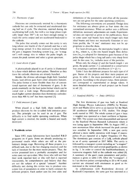
28 6 C Travier / <strong>Rf</strong> <strong>guns</strong> <strong>bright</strong> <strong>injectors</strong> <strong>for</strong> <strong>FEL</strong><br />
2.1 . Thermionic rf gun<br />
Electrons are continuously emitted by a thermionic<br />
cathode but can only be extracted and accelerated during<br />
half an rf cycle. The electrons, emitted during the<br />
accelerating half cycle, but with a too large phase (typically<br />
larger than 100') do not have enough energy to<br />
reach the cavity output and are accelerated backward to<br />
the cathode .<br />
The pulse that actually comes out the cavity is very<br />
long (about one fourth of the rf period) and has a very<br />
large energy spread . It is thus necessary to place behind<br />
the gun a magnetic bunching system (e .g ., an "a-magnet")<br />
with energy slits to reduce the pulse length, increase,the<br />
peak current and select a given spectrum .<br />
2 .2 . Laser-driven rf <strong>guns</strong><br />
A photocathode placed in an rf cavity is illuminated<br />
by a laser which delivers short pulses . There<strong>for</strong>e as they<br />
leave the cathode, electrons are already bunched .<br />
Besides the obvious advantages (high field, bunched<br />
beam), laser-driven <strong>guns</strong> have other attractive features .<br />
The pulse <strong>for</strong>mat is more flexible than that of conventional<br />
<strong>injectors</strong> and that of thermionic rf <strong>guns</strong>. It depends<br />
essentially on the laser pulse <strong>for</strong>mat which can be<br />
varied over a wide range. Photocathodes can deliver<br />
much higher current densities than thermionic cathodes :<br />
more than 400 A/cm2 has been reported [3] .<br />
2 .3 Field emission rf <strong>guns</strong><br />
When placed in a high field, sharp needles can<br />
produce electrons by the so-called field emission process<br />
. This principle can be used in an rf gun . The<br />
difficulty is to find stable operating conditions . When<br />
high current is emitted, the needle is heated and easily<br />
destroyed .<br />
3 . Worldwide review<br />
Since 1983, many laboratories have launched R&D<br />
programs on rf <strong>guns</strong> . Some are already producing experimental<br />
results while others are still at the preliminary<br />
design stage. Reviewing all these projects is a<br />
difficult task, due to the fast changing situation and the<br />
lack of literature <strong>for</strong> the most recent projects . Thus, the<br />
review presented here is probably incomplete and <strong>for</strong><br />
some cases not up-to-date . May those who will not find<br />
their work reported here or who will find it reported<br />
inaccurately, be comprehensive and believe that they<br />
are not the subject of a special "censure" . Another<br />
difficulty met during this review was to produce consistent<br />
lists of parametersmorder to fairly compare the<br />
different projects . Each author uses his own units and<br />
definitions of the parameters and often all the parameters<br />
are not given <strong>for</strong> the same operating conditions .<br />
The following conventions are assumed . Design data<br />
<strong>for</strong> emittance are always given as four times the rms<br />
normalized emittance . When an author uses a different<br />
definition, necessary adjustments are made . Experimental<br />
data are reported as given in the publications . Since<br />
in some cases real beams have much longer tails than<br />
ideal beams and have not necessarily Gaussian or uni<strong>for</strong>m<br />
profile, the "4 rms" emittance may not be appropriate<br />
to describe them .<br />
For laser-driven <strong>guns</strong>, the rmcropulse length is taken<br />
as 4a b , where ab is the rms bunch length . Rms definition<br />
(lab) is adopted <strong>for</strong> thermionic <strong>guns</strong> because of the<br />
pulse shape which has a long tail and a very sharp front<br />
end . In this case, la b includes most of the particles .<br />
When only the charge Q and the bunch length T are<br />
given, the peak current I is calculated in a conservative<br />
way assuring a uni<strong>for</strong>m distribution (I = Q/T ) .<br />
Table 1 lists the different projects <strong>for</strong> each type of rf<br />
gun . Status of the projects and their main purpose are<br />
given . In table 2, the main parameters of each project<br />
are given . According to the project status, these parameters<br />
correspond to experimental or design values . A<br />
more detailed description of each project can be found<br />
in ref. [1] .<br />
3.1 . Stan<strong>for</strong>d (HEPL) - Duke (D<strong>FEL</strong>L)<br />
The first thermionic rf gun was built at Stan<strong>for</strong>d<br />
High Energy Physics Laboratory (HEPL) by Westenskow<br />
and Madey [2] to serve as an injector <strong>for</strong> the Mark<br />
III accelerator dedicated to <strong>FEL</strong> studies . The design<br />
work started in 1983 . The whole system (rf gun + lmac<br />
+ wiggler) was operated as a laser oscillator in September<br />
1985 . The system was then disassembled and moved<br />
to the Stan<strong>for</strong>d Photon Research Laboratory where it<br />
was lasing again in September 1986 . In August 1987, a<br />
new momentum filter which increased the peak current<br />
was installed . In September 1988, a new gun cavity<br />
allowed a more stable operation with longer rf macropulses<br />
(8 Ws) repeated at a higher frequency (15 Hz) .<br />
The thermionic gun consists of a LaB6 cathode placed<br />
in an rf cavity operated at 2857 MHz . The cavity is<br />
followed by a transport system including an "a-magnet"<br />
with momentum filter and several quadrupoles, as shown<br />
in fig. 3 . In order to control the backbombardment, a<br />
transverse magnetic field at the cathode was added [8] .<br />
A summary of the gun's main parameters and per<strong>for</strong>mances<br />
is given in table 2 [9] . After the "ci-magnet", 2<br />
to 3 ps electron pulses corresponding to 20 to 40 A peak<br />
current are obtained with emittances as good as 41T<br />
mm mrad in the vertical plane .<br />
In collaboration with Rocketdyne division of<br />
Rockwell Corporation, the same gun was operated as a
![TUNLXXXIV.tex typeset [1] - Triangle Universities Nuclear Laboratory](https://img.yumpu.com/47618358/1/190x245/tunlxxxivtex-typeset-1-triangle-universities-nuclear-laboratory.jpg?quality=85)