ELC Series, JL 680-2 - Coffing Hoists, Coffing Hoist Parts
ELC Series, JL 680-2 - Coffing Hoists, Coffing Hoist Parts
ELC Series, JL 680-2 - Coffing Hoists, Coffing Hoist Parts

You also want an ePaper? Increase the reach of your titles
YUMPU automatically turns print PDFs into web optimized ePapers that Google loves.
Country Club Road<br />
P.O. Box 779<br />
Wadesboro, NC 28170 USA<br />
TEL: (800) 477-5003<br />
FAX: (800) 374-6853<br />
Adjusting Lower Limit (Silver Nut)<br />
Refer to Figure 3.<br />
1. Suspend the hoist. Carefully lower the load block to a point<br />
where the slack-end loop of the chain hangs down 6" or<br />
more from the hoist housing (or the limit desired in any<br />
particular application allowing the minimum 6"). There<br />
should be a minimum clearance of 1½" between the chain<br />
stop and bottom of hoist.<br />
2. DISCONNECT HOIST FROM POWER SUPPLY and<br />
remove the electrical cover.<br />
3. With a screwdriver, pry the spring guide plate out of the slots<br />
in the limit switch nuts.<br />
4. Turn the slotted silver nut toward its limit switch until the<br />
switch “clicks,” then turn two slots farther. Release the spring<br />
guide plate and be sure it slips back in the slots in both limit<br />
switch nuts. Do not disturb the gold slotted nut if it has been<br />
set previously.<br />
B<br />
E<br />
Gap<br />
A<br />
X<br />
D<br />
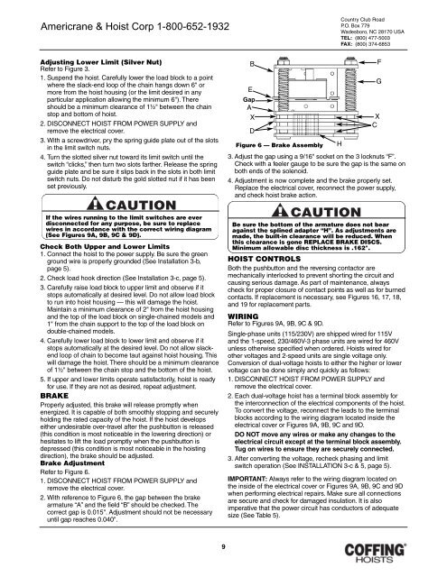
Figure 6 — Brake Assembly<br />
3. Adjust the gap using a 9/16" socket on the 3 locknuts “F”.<br />
Check with a feeler gauge to be sure the gap is the same on<br />
both ends of the solenoid.<br />
4. Adjustment is now complete and the brake properly set.<br />
Replace the electrical cover, reconnect the power supply,<br />
and check hoist brake action.<br />
H<br />
F<br />
G<br />
X<br />
C<br />
If the wires running to the limit switches are ever<br />
disconnected for any purpose, be sure to replace<br />
wires in accordance with the correct wiring diagram<br />
(See Figures 9A, 9B, 9C & 9D).<br />
Check Both Upper and Lower Limits<br />
1. Connect the hoist to the power supply. Be sure the green<br />
ground wire is properly grounded (See Installation 3-b,<br />
page 5).<br />
2. Check load hook direction (See Installation 3-c, page 5).<br />
3. Carefully raise load block to upper limit and observe if it<br />
stops automatically at desired level. Do not allow load block<br />
to run into hoist housing — this will damage the hoist.<br />
Maintain a minimum clearance of 2" from the hoist housing<br />
and the top of the load block on single-chained models and<br />
1" from the chain support to the top of the load block on<br />
double-chained models.<br />
4. Carefully lower load block to lower limit and observe if it<br />
stops automatically at the desired level. Do not allow slackend<br />
loop of chain to become taut against hoist housing. This<br />
will damage the hoist. There should be a minimum clearance<br />
of 1½" between the chain stop and the bottom of the hoist.<br />
5. If upper and lower limits operate satisfactorily, hoist is ready<br />
for use. If they are not as desired, repeat adjustment.<br />
BRAKE<br />
Properly adjusted, this brake will release promptly when<br />
energized. It is capable of both smoothly stopping and securely<br />
holding the rated capacity of the hoist. If the hoist develops<br />
either undesirable over-travel after the pushbutton is released<br />
(this condition is most noticeable in the lowering direction) or<br />
hesitates to lift the load promptly when the pushbutton is<br />
depressed (this condition is most noticeable in the hoisting<br />
direction), the brake should be adjusted.<br />
Brake Adjustment<br />
Refer to Figure 6.<br />
1. DISCONNECT HOIST FROM POWER SUPPLY and<br />
remove the electrical cover.<br />
2. With reference to Figure 6, the gap between the brake<br />
armature “A” and the field “B” should be checked. The<br />
correct gap is 0.015". Adjustment should not be necessary<br />
until gap reaches 0.040".<br />
Be sure the bottom of the armature does not bear<br />
against the splined adapter “H”. As adjustments are<br />
made, the built-in clearance will be reduced. When<br />
this clearance is gone REPLACE BRAKE DISCS.<br />
Minimum allowable disc thickness is .162".<br />
HOIST CONTROLS<br />
Both the pushbutton and the reversing contactor are<br />
mechanically interlocked to prevent shorting the circuit and<br />
causing serious damage. As part of maintenance, always<br />
check for proper closure of contact points as well as for burned<br />
contacts. If replacement is necessary, see Figures 16, 17, 18,<br />
and 19 for replacement parts.<br />
WIRING<br />
Refer to Figures 9A, 9B, 9C & 9D.<br />
Single-phase units (115/230V) are shipped wired for 115V<br />
and the 1-speed, 230/460V-3 phase units are wired for 460V<br />
unless otherwise specified when ordered. <strong><strong>Hoist</strong>s</strong> wired for<br />
other voltages and 2-speed units are single voltage only.<br />
Conversion of dual-voltage hoists to either the higher or lower<br />
voltage can be done simply and quickly as follows:<br />
1. DISCONNECT HOIST FROM POWER SUPPLY and<br />
remove the electrical cover.<br />
2. Each dual-voltage hoist has a terminal block assembly for<br />
the interconnection of the electrical components of the hoist.<br />
To convert the voltage, reconnect the leads to the terminal<br />
blocks according to the wiring diagram located inside the<br />
electrical cover or Figures 9A, 9B, 9C and 9D.<br />
DO NOT move any wires or make any changes to the<br />
electrical circuit except at the terminal block assembly.<br />
Tug on wires to ensure they are securely connected.<br />
3. After converting the voltage, recheck phasing and limit<br />
switch operation (See INSTALLATION 3-c & 5, page 5).<br />
IMPORTANT: Always refer to the wiring diagram located on<br />
the inside of the electrical cover or Figures 9A, 9B, 9C and 9D<br />
when performing electrical repairs. Make sure all connections<br />
are secure and check for damaged insulation. It is also<br />
imperative that the power circuit has conductors of adequate<br />
size (See Table 5).<br />
9