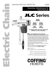
ELC Series, JL 680-2 - Coffing Hoists, Coffing Hoist Parts
ELC Series, JL 680-2 - Coffing Hoists, Coffing Hoist Parts
ELC Series, JL 680-2 - Coffing Hoists, Coffing Hoist Parts

Create successful ePaper yourself
Turn your PDF publications into a flip-book with our unique Google optimized e-Paper software.
Country Club Road<br />
P.O. Box 779<br />
Wadesboro, NC 28170 USA<br />
TEL: (800) 477-5003<br />
FAX: (800) 374-6853<br />
LUBRICATION<br />
Refer to Figure 11.<br />
Proper lubrication is necessary for a long and relatively troublefree<br />
hoist operation. Refer to the following and the<br />
RECOMMENDED LUBRICATION SCHEDULE for lubrication<br />
points, type of lubricant, and frequency of lubrication.<br />
Load Chain<br />
Clean the load chain with acid-free solvent and coat with SAE<br />
90 gear oil. Wipe excess oil to prevent dripping. Never apply<br />
grease to the chain.<br />
Gearing<br />
The gear case of this hoist is filled at assembly with<br />
approximately 1½ pints of SAE 90 EP gear oil. Check oil level<br />
by removing the oil level check plug from the side of the hoist.<br />
With the hoist hanging level, gear oil should be even with the<br />
hole. Change oil periodically depending on the severity of the<br />
application and the environmental conditions (at least every<br />
200 hours of run time).<br />
Bearings<br />
All bearings except hook and idler sheave bearings are<br />
lubricated at the factory and should not require additional<br />
lubrication. Noisy or worn bearings should be replaced.<br />
Limit Switch Shaft<br />
Remove any dirt accumulation and spray with a general<br />
purpose lubricant.<br />
Hook Bearing<br />
Apply a few drops of SAE 30 gear or motor oil around the edge<br />
of the bearing.<br />
Idler Sheave Bearing (Bushing)<br />
Disassemble load block and apply a light coat of NLGI #2<br />
grease, or equivalent, inside of bearing.<br />
HOIST REPAIRS<br />
1. For major repairs or when the hoist is to be sectioned in the<br />
suspension area, it will be necessary to move the hoist to a<br />
workbench or table.<br />
2. For repairs which can be done by removing the electrical<br />
cover only, the hoist need not be moved. Lowering the hoist<br />
to a convenient working level is desirable.<br />
NOTE: If you do not have an experienced mechanic to do your<br />
repair work, we recommend that you send your hoist to an<br />
approved service station for repairs. Use authorized repair<br />
parts only.<br />
Remove load and disconnect hoist from power supply<br />
before starting to do any repairs or to take any<br />
sections apart.<br />
The following repair instructions will help you in understanding<br />
repair procedures, when related to the Replacement <strong>Parts</strong><br />
List starting on page 18. For clarity these are broken down<br />
into areas.<br />
Electrical <strong>Parts</strong> and Brake<br />
1. Refer to Figures 16 and 17. Remove the cover to access the<br />
controls. Single-phase models also have a starting switch and<br />
capacitor mounted on the motor as shown in Figure 13. The<br />
terminal blocks and end clamps snap off of the rails on the<br />
plate using a small screwdriver. DO NOT SLIDE THE END<br />
CLAMPS.<br />
The reversing contactor can be slid off the rail, but it must be<br />
snapped on. Where the contactor fits the rail, one side has<br />
springs or pads that apply pressure against the edge of the<br />
rail. By pressing against that side at the base of the contactor,<br />
you can snap the part on or off using a rotating action. Note<br />
the numbers that label the terminals on the contactor and<br />
orient the part as shown in Figures 9A-9D. Single-phase<br />
contactors have a small jumper that is not present on the<br />
3-phase (note the 3 and 5 terminals on the reversing<br />
contactor in Figure 9A).<br />
Figure 7 - Electrical Panel Removed<br />
2. Remove the electrical panel by removing the stand-off<br />
screws (See Figures 16 & 17). The limit switch and brake are<br />
now accessible as shown in Figure 7.<br />
3. Remove the transformer bolted to the back of the panel plate<br />
if it requires replacement.<br />
4. Refer to Figure 15 to disassemble the brake. See BRAKE<br />
ADJUSTMENT on page 9 to properly set the brake.<br />
5. Refer to Figures 20 and 21 to disassemble the limit switch.<br />
See LIMIT SWITCH ADJUSTMENT on page 8 to properly<br />
set the upper and lower limits of travel.<br />
6. Refer to Figures 18 and 19 for repairs on the pushbutton<br />
station. Also refer to the wiring diagram inside the electrical<br />
cover or Figures 9A, 9B, 9C and 9D for wiring instructions.<br />
Motor<br />
Refer to Figures 12, 13 and 14.<br />
The hoist motor is located on the opposite end to that of the<br />
electrical parts, but the two are tied together with electrical<br />
leads running through the housing.<br />
1. If it is necessary to replace or repair the motor,<br />
DISCONNECT THE HOIST FROM THE POWER SUPPLY<br />
and remove the electrical cover.<br />
2. Loosen the screw clamps on the terminal blocks and<br />
reversing contactor to disconnect the motor leads<br />
(See Figures 16 and 17).<br />
3. Remove the four motor mounting bolts attaching the motor<br />
to the housing. It will come loose at the motor coupling.<br />
4. Inspect the motor coupling, motor shaft and all the bearings.<br />
Replace as necessary.<br />
5. Install new or repaired motor according to the wiring diagram<br />
located inside the electrical cover or Figures 9A, 9B, 9C<br />
and 9D.<br />
10