ELC Series, JL 680-2 - Coffing Hoists, Coffing Hoist Parts
ELC Series, JL 680-2 - Coffing Hoists, Coffing Hoist Parts
ELC Series, JL 680-2 - Coffing Hoists, Coffing Hoist Parts

Create successful ePaper yourself
Turn your PDF publications into a flip-book with our unique Google optimized e-Paper software.
Country Club Road<br />
P.O. Box 779<br />
Wadesboro, NC 28170 USA<br />
TEL: (800) 477-5003<br />
FAX: (800) 374-6853<br />
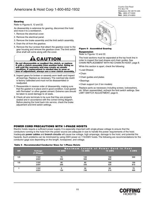
Gearing<br />
Refer to Figures 8, 12 and 22.<br />
As disassembly is extensive for gearing, disconnect the hoist<br />
and move it to a workbench.<br />
1. Remove the electrical cover.<br />
2. Remove the electrical panel.<br />
3. Remove the brake assembly and the limit switch assembly.<br />
4. Drain the oil from the gearbox.<br />
5. Remove the four screws that attach the gearbox cover to the<br />
gear housing and remove the gearbox cover. The limit switch<br />
drive shaft will come along with the cover.<br />
Do not disassemble or readjust the clutch, or replace<br />
it with a clutch assembly from another hoist. Doing so<br />
will void the warranty and may create an unsafe<br />
condition. If replacement is needed due to wear or<br />
loss of adjustment, always use a new clutch assembly.<br />
6. Inspect gears for broken or severely worn teeth and inspect<br />
all bearings. Replace as necessary. The overload slip clutch<br />
is factory calibrated and must not be disassembled or<br />
readjusted.<br />
7. Reassemble in reverse order of disassembly, making sure<br />
that the gasket is in place and in good condition. Coat gasket<br />
with Permatex ® or other gasket cement. Extreme care should<br />
be taken to avoid damage to oil seals.<br />
8. Check all wire terminals to be sure that they are properly<br />
seated and in accordance with the correct wiring diagram.<br />
Before placing the hoist back into service, check the brake<br />
adjustment and limit switch settings.<br />
Figure 8 - Assembled Gearing<br />
Suspension<br />
Refer to Figures 12 and 22.<br />
The hoist sections must be separated at the top hook line in<br />
order to inspect the load sheave and chain guides. See<br />
CHAIN REPLACEMENT WITH NO CHAIN IN HOIST, page 8.<br />
While this section is apart, check the following:<br />
• Load Sheave<br />
• Chain<br />
• Chain guides and plates<br />
• Bearings<br />
• Chain support (on 2 ton models)<br />
Replace parts as necessary including screws, lockwashers,<br />
etc. When reassembled, recheck the limit switch settings. See<br />
LIMIT SWITCH ADJUSTMENT, page 8.<br />
POWER CORD PRECAUTIONS WITH 1-PHASE HOISTS<br />
Electric hoists require a sufficient power supply. It is especially important with single-phase voltage to ensure that the<br />
conductors running to the hoist from the power source are adequate in size to handle the power requirements of the hoist.<br />
Inadequate power cables and branch circuits will cause low voltage, high amperage, damage to the hoist, and potential fire<br />
hazards. Such problems can be minimized by using 230V power on 115/230V hoists. The following are recommendations for the<br />
conductor gage size depending on the length, horsepower, and voltage.<br />
Table 5 - Recommended Conductor Sizes for 1-Phase <strong><strong>Hoist</strong>s</strong><br />
Maximum Length of Power Cord in Feet<br />
HP Voltage 14 AWG 12 AWG 10 AWG 8 AWG<br />
(1-Phase)<br />
1/4 115V 75 120 190 300<br />
230V 350 560 900<br />
1/2 115V 40 60 100 150<br />
230V 200 330 520 810<br />
1 115V 0 30 50 75<br />
230V 120 190 310 490<br />
11