ELC Series, JL 680-2 - Coffing Hoists, Coffing Hoist Parts
ELC Series, JL 680-2 - Coffing Hoists, Coffing Hoist Parts
ELC Series, JL 680-2 - Coffing Hoists, Coffing Hoist Parts

Create successful ePaper yourself
Turn your PDF publications into a flip-book with our unique Google optimized e-Paper software.
Country Club Road<br />
P.O. Box 779<br />
Wadesboro, NC 28170 USA<br />
TEL: (800) 477-5003<br />
FAX: (800) 374-6853<br />
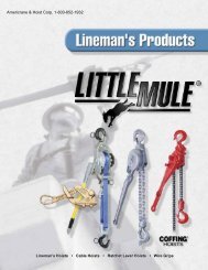
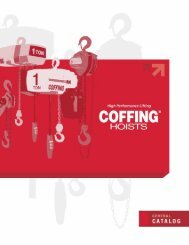
Dead-End<br />
Screw<br />
2<br />
TON<br />
Slack End<br />
TON<br />
Load End<br />
Double-chained<br />
<strong>Hoist</strong><br />
Chain Support<br />
Figure 4 — Chain Replacement Diagram<br />
Single-chained<br />
<strong>Hoist</strong><br />
13. Attach the bottom block on single-chained hoists using a<br />
new load block screw (See Figure 23). On double-chained<br />
hoists, feed the chain through the load block (welds<br />
of the upstanding links will be in towards the sheave) and<br />
fasten the end of the chain to the chain support using a<br />
new chain support pin (See Figure 23). Be sure there are<br />
no twists in the chain.<br />
14. Adjust the upper limit switch (See ADJUSTING UPPER<br />
LIMIT, page 8).<br />
Chain Replacement with No Chain in <strong>Hoist</strong><br />
Refer to Figures 4 and 5.<br />
1. DISCONNECT HOIST FROM POWER SUPPLY and move<br />
hoist to a work table. Do not remove the electrical cover.<br />
2. Lay the hoist on its side and remove the four screws that<br />
attach the sheave housing to the gear housing<br />
(See Figure 12, Ref. No. 2).<br />
3. Carefully pull the sheave housing and motor assembly loose<br />
from the gear housing.<br />
There are wires running through the hoist. Carefully<br />
ease the hoist sections apart. Do not jerk them apart.<br />
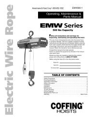
4. Turn the two hoist sections at right angles and remove the<br />
chain guide screws and the nearest chain guide (Ref. No. 1,<br />
Figure 5).<br />
5. Remove the two chain guide plate screws (Ref. No. 2) and<br />
the nearest chain guide plate. Be careful not to lose the two<br />
spacers that are between the chain guide plates.<br />
NOTE: Inspect chain guides and load sheave for wear,<br />
replace as needed.<br />
6. Lay the new chain over the load sheave. Allow about 15" of<br />
chain below the hoist on the slack end (See Figure 4). Be sure<br />
the welds of the upstanding links are out away from the load<br />
sheave and that proper orientation is observed for attachment<br />
of the dead end. Also be sure the load hook assembly (if<br />
already attached to the chain) is toward the center of the hoist<br />
or to your right as you face the load sheave.<br />
7. Replace the chain guide plate and the chain guide. Grease<br />
the splined shafts that project from both the housing and<br />
the motor.<br />
1<br />
Figure 5 — Chain Replacement with No Chain in <strong>Hoist</strong><br />
8. Place the motor coupling on the splined shaft and carefully<br />
fit the two hoist sections together. Be sure the dead-end nut,<br />
the top hook and the chain support (double-chained hoists<br />
only) are all in place. On single-chained hoists, the hook<br />
shank goes in the center hole; on double-chained hoists, it<br />
goes in the off-center hole (See Figure 4). Be careful not to<br />
pinch any of the wiring. Turn the hoist on its side and replace<br />
the four screws and tighten securely.<br />
9. Follow steps 11 through 14 in the previous section, CHAIN<br />
REPLACEMENT WITH CHAIN IN HOIST, to complete the<br />
chain replacement procedure.<br />
LIMIT SWITCH ADJUSTMENT<br />
IMPORTANT: Before placing hoist in operation, check the limit<br />
switch adjustment. Limit switches are provided to protect the<br />
hoist against damage resulting from overtravel or to allow setting<br />
the hook travel within the factory-set limits of travel. The standard<br />
limit switch is designed for lifts of 50 ft or less on single-chained<br />
hoists and 25 ft or less on the 2 ton, double-chained models. The<br />
long lift limit switch allows for the maximum amount of lift, which<br />
is 134 ft on 1/2 ton and under models, 143 ft on the 1 ton<br />
models, and 71 ft on the 2 ton models.<br />
The upper and lower limit switch adjusting nuts are color-coded<br />
gold and silver respectively. Each limit nut has 10 slots for fine<br />
adjustment, and the increment of adjustment is such that one<br />
slot is equivalent to approximately one link of chain travel with<br />
the standard limit switch. Movement of the limit switch nuts<br />
toward or away from each other increases or decreases the<br />
hook travel respectively.<br />
Adjusting Upper Limit (Gold Nut)<br />
Refer to Figure 3.<br />
1. Suspend the hoist. For single chain models raise the load<br />
block until there is a minimum clearance of 2" from the hoist<br />
housing and the top of the block. Double chain models<br />
require a minimum clearance of 1" from the chain support to<br />
the top of the load block.<br />
2. DISCONNECT HOIST FROM POWER SUPPLY and<br />
remove the electrical cover.<br />
3. With a screwdriver, pry the spring guide plate out of the slots<br />
in the limit switch nuts.<br />
4. Turn the slotted gold nut toward its limit switch until the<br />
switch “clicks” then turn two slots farther. Release the spring<br />
guide plate and be sure it slips back into the slots in both<br />
limit switch nuts. Do not disturb the silver slotted nut if it has<br />
been set previously.<br />
8