EZ COMMAND - Treinelektronika.com
EZ COMMAND - Treinelektronika.com
EZ COMMAND - Treinelektronika.com

You also want an ePaper? Increase the reach of your titles
YUMPU automatically turns print PDFs into web optimized ePapers that Google loves.
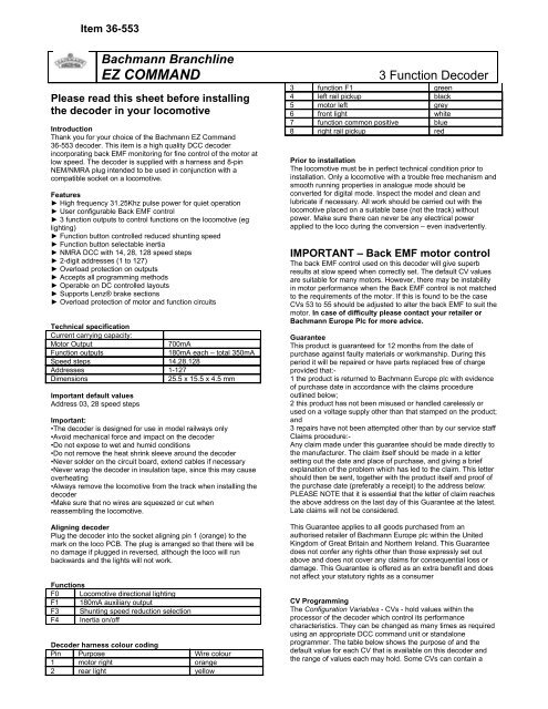
Item 36-553<br />
Bachmann Branchline<br />
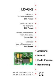
<strong>EZ</strong> <strong>COMMAND</strong><br />
Please read this sheet before installing<br />
the decoder in your lo<strong>com</strong>otive<br />
Introduction<br />
Thank you for your choice of the Bachmann <strong>EZ</strong> Command<br />
36-553 decoder. This item is a high quality DCC decoder<br />
incorporating back EMF monitoring for fine control of the motor at<br />
low speed. The decoder is supplied with a harness and 8-pin<br />
NEM/NMRA plug intended to be used in conjunction with a<br />
<strong>com</strong>patible socket on a lo<strong>com</strong>otive.<br />
Features<br />
► High frequency 31.25Khz pulse power for quiet operation<br />
► User configurable Back EMF control<br />
► 3 function outputs to control functions on the lo<strong>com</strong>otive (eg<br />
lighting)<br />
► Function button controlled reduced shunting speed<br />
► Function button selectable inertia<br />
► NMRA DCC with 14, 28, 128 speed steps<br />
► 2-digit addresses (1 to 127)<br />
► Overload protection on outputs<br />
► Accepts all programming methods<br />
► Operable on DC controlled layouts<br />
► Supports Lenz® brake sections<br />
► Overload protection of motor and function circuits<br />
Technical specification<br />
Current carrying capacity:<br />
Motor Output<br />
700mA<br />
Function outputs<br />
180mA each – total 350mA<br />
Speed steps 14,28,128<br />
Addresses 1-127<br />
Dimensions<br />
25.5 x 15.5 x 4.5 mm<br />
Important default values<br />
Address 03, 28 speed steps<br />
Important:<br />
•The decoder is designed for use in model railways only<br />
•Avoid mechanical force and impact on the decoder<br />
•Do not expose to wet and humid conditions<br />
•Do not remove the heat shrink sleeve around the decoder<br />
•Never solder on the circuit board, extend cables if necessary<br />
•Never wrap the decoder in insulation tape, since this may cause<br />
overheating<br />
•Always remove the lo<strong>com</strong>otive from the track when installing the<br />
decoder<br />
•Make sure that no wires are squeezed or cut when<br />
reassembling the lo<strong>com</strong>otive.<br />
Aligning decoder<br />
Plug the decoder into the socket aligning pin 1 (orange) to the<br />
mark on the loco PCB. The plug is arranged so that there will be<br />
no damage if plugged in reversed, although the loco will run<br />
backwards and the lights will not work.<br />
Functions<br />
F0 Lo<strong>com</strong>otive directional lighting<br />
F1 180mA auxiliary output<br />
F3 Shunting speed reduction selection<br />
F4 Inertia on/off<br />
Decoder harness colour coding<br />
Pin Purpose Wire colour<br />
1 motor right orange<br />
2 rear light yellow<br />
3 Function Decoder<br />
3 function F1 green<br />
4 left rail pickup black<br />
5 motor left grey<br />
6 front light white<br />
7 function <strong>com</strong>mon positive blue<br />
8 right rail pickup red<br />
Prior to installation<br />
The lo<strong>com</strong>otive must be in perfect technical condition prior to<br />
installation. Only a lo<strong>com</strong>otive with a trouble free mechanism and<br />
smooth running properties in analogue mode should be<br />
converted for digital mode. Inspect the model and clean and<br />
lubricate if necessary. All work should be carried out with the<br />
lo<strong>com</strong>otive placed on a suitable base (not the track) without<br />
power. Make sure there can never be any electrical power<br />
applied to the loco during the conversion – even inadvertently.<br />
IMPORTANT – Back EMF motor control<br />
The back EMF control used on this decoder will give superb<br />
results at slow speed when correctly set. The default CV values<br />
are suitable for many motors. However, there may be instability<br />
in motor performance when the Back EMF control is not matched<br />
to the requirements of the motor. If this is found to be the case<br />
CVs 53 to 55 should be adjusted to alter the back EMF to suit the<br />
motor. In case of difficulty please contact your retailer or<br />
Bachmann Europe Plc for more advice.<br />
Guarantee<br />
This product is guaranteed for 12 months from the date of<br />
purchase against faulty materials or workmanship. During this<br />
period it will be repaired or have parts replaced free of charge<br />
provided that:-<br />
1 the product is returned to Bachmann Europe plc with evidence<br />
of purchase date in accordance with the claims procedure<br />
outlined below;<br />
2 this product has not been misused or handled carelessly or<br />
used on a voltage supply other than that stamped on the product;<br />
and<br />
3 repairs have not been attempted other than by our service staff<br />
Claims procedure:-<br />
Any claim made under this guarantee should be made directly to<br />
the manufacturer. The claim itself should be made in a letter<br />
setting out the date and place of purchase, and giving a brief<br />
explanation of the problem which has led to the claim. This letter<br />
should then be sent, together with the product itself and proof of<br />
the purchase date (preferably a receipt) to the address below:<br />
PLEASE NOTE that it is essential that the letter of claim reaches<br />
the above address on the last day of this Guarantee at the latest.<br />
Late claims will not be considered.<br />
This Guarantee applies to all goods purchased from an<br />
authorised retailer of Bachmann Europe plc within the United<br />
Kingdom of Great Britain and Northern Ireland. This Guarantee<br />
does not confer any rights other than those expressly set out<br />
above and does not cover any claims for consequential loss or<br />
damage. This Guarantee is offered as an extra benefit and does<br />
not affect your statutory rights as a consumer<br />
CV Programming<br />
The Configuration Variables - CVs - hold values within the<br />
processor of the decoder which control its performance<br />
characteristics. They can be changed as many times as required<br />
using an appropriate DCC <strong>com</strong>mand unit or standalone<br />
programmer. The table below shows the purpose of and the<br />
default value for each CV that is available on this decoder and<br />
the range of values each may hold. Some CVs can contain a
Item 36-553<br />
value from a range (eg start voltage) whilst others use the<br />
individual ‘bits’ of the CV to act as on/off switches for features (eg<br />
direction of operation). Inappropriate CV values may cause the<br />
decoder to operate incorrectly: if in doubt please take advice<br />
from your retailer or Bachmann Europe plc.<br />
Table of CV Values<br />
CV Description Range Default<br />
1 Primary Address 1-127 3<br />
2 Start voltage 1-63 3<br />
3 Acceleration rate 0-63 8<br />
4 Deceleration rate 0-63 6<br />
5 Max voltage 0-63 63<br />
7 Version number 0 0<br />
8 Manufacturer ID ESU 151<br />
Effect<br />
when<br />
Bit value<br />
0<br />
Effect when<br />
Bit value 1<br />
29 Decoder configuration<br />
6<br />
data<br />
Bit 0 Direction of operation 0 Normal Reversed<br />
Bit 1 Speed steps 1 14 28/128<br />
Bit 2 Loco operates on DC 1 Disabled Enabled<br />
Bits 3 to 7<br />
Not used<br />
49 Back EMF Selector 1<br />
Bit 0 1 Disabled Enabled<br />
Bits 1 to 7<br />
51 DC Brake Control 1<br />
Bit 0 Lenz DC brake mode 1 Disabled Enabled<br />
Bits 1 to 7<br />
Not used<br />
53 Feedback reference Determines the back EMF that the motor<br />
should supply at maximum speed. The<br />
more efficient the motor, the higher this<br />
value may be. Reduce this value if the<br />
engine does not reach its designed<br />
maximum speed.<br />
54 Feedback Parameter<br />
K<br />
55 Feedback parameter<br />
I<br />
Determines the load control effect. The<br />
higher the value, the stronger the impact<br />
on the motor.<br />
Determines the momentum of the motor.<br />
Motors with large flywheels of large<br />
diameter require a smaller value.<br />
0-63 42<br />
0-63 32<br />
0-63 24<br />
63 Function brightness Applies to both F0 and F1 0-7 7<br />
Decoder reset<br />
The values can be reset to the defaults as<br />
above by writing value 08 to CV 8<br />
Lo<strong>com</strong>otive lights<br />
Your DCC equipment instructions will tell<br />
you how to turn the lights on and off –<br />
usually F0 (or F10 on <strong>EZ</strong> Command). If this<br />
does not turn them on check the alignment<br />
of the decoder and reverse if necessary<br />
Bachmann Europe plc<br />
Moat Way, Barwell, Leicestershire, LE9 8EY<br />
01455 841756<br />
www.bachmann.co.uk