PDT6100 Product Ref Guide1.44 MB - Support
PDT6100 Product Ref Guide1.44 MB - Support
PDT6100 Product Ref Guide1.44 MB - Support

You also want an ePaper? Increase the reach of your titles
YUMPU automatically turns print PDFs into web optimized ePapers that Google loves.
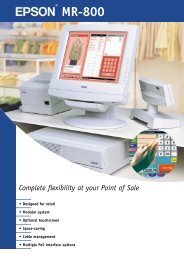
PDT 6100 Series<br />
<strong>Product</strong> <strong>Ref</strong>erence Guide
PDT 6100 Series<br />
<strong>Product</strong> <strong>Ref</strong>erence Guide<br />
70-33222-02<br />
Revision A<br />
June 2001
© 2001 by Symbol Technologies, Inc. All rights reserved.<br />
No part of this publication may be reproduced or used in any form, or by any electrical or<br />
mechanical means, without permission in writing from Symbol. This includes electronic or<br />
mechanical means, such as photocopying, recording, or information storage and retrieval<br />
systems. The material in this manual is subject to change without notice.<br />
The software is provided strictly on an “as is” basis. All software, including firmware,<br />
furnished to the user is on a licensed basis. Symbol grants to the user a non-transferable and<br />
non-exclusive license to use each software or firmware program delivered hereunder (licensed<br />
program). Except as noted below, such license may not be assigned, sublicensed, or otherwise<br />
transferred by the user without prior written consent of Symbol. No right to copy a licensed<br />
program in whole or in part is granted, except as permitted under copyright law. The user<br />
shall not modify, merge, or incorporate any form or portion of a licensed program with other<br />
program material, create a derivative work from a licensed program, or use a licensed<br />
program in a network without written permission from Symbol. The user agrees to maintain<br />
Symbol’s copyright notice on the licensed programs delivered hereunder, and to include the<br />
same on any authorized copies it makes, in whole or in part. The user agrees not to<br />
decompile, disassemble, decode, or reverse engineer any licensed program delivered to the<br />
user or any portion thereof.<br />
Symbol reserves the right to make changes to any software or product to improve reliability,<br />
function, or design.<br />
Symbol does not assume any product liability arising out of, or in connection with, the<br />
application or use of any product, circuit, or application described herein.<br />
No license is granted, either expressly or by implication, estoppel, or otherwise under any<br />
Symbol Technologies, Inc., intellectual property rights. An implied license only exists for<br />
equipment, circuits, and subsystems contained in Symbol products.<br />
Symbol, Spectrum One, and Spectrum24 are registered trademarks of Symbol Technologies,<br />
Inc. Other product names mentioned in this manual may be trademarks or registered<br />
trademarks of their respective companies and are hereby acknowledged.<br />
Symbol Technologies, Inc.<br />
One Symbol Plaza<br />
Holtsville, New York 11742-1300<br />
http://www.symbol.com<br />
ii
Contents<br />
About This Guide<br />
Notational Conventions . . . . . . . . . . . . . . . . . . . . . . . . . . . . . . . . . . . . . . . . . . . . . . . . . . . . . . . . . . vii<br />
Related Publications . . . . . . . . . . . . . . . . . . . . . . . . . . . . . . . . . . . . . . . . . . . . . . . . . . . . . . . . . . . . . vii<br />
Service Information . . . . . . . . . . . . . . . . . . . . . . . . . . . . . . . . . . . . . . . . . . . . . . . . . . . . . . . . . . . . . viii<br />
Symbol <strong>Support</strong> Center . . . . . . . . . . . . . . . . . . . . . . . . . . . . . . . . . . . . . . . . . . . . . . . . . . . . . . . . ix<br />
Warranty . . . . . . . . . . . . . . . . . . . . . . . . . . . . . . . . . . . . . . . . . . . . . . . . . . . . . . . . . . . . . . . . . . . . . .xi<br />
Warranty Coverage and Procedure . . . . . . . . . . . . . . . . . . . . . . . . . . . . . . . . . . . . . . . . . . . . . . xii<br />
General . . . . . . . . . . . . . . . . . . . . . . . . . . . . . . . . . . . . . . . . . . . . . . . . . . . . . . . . . . . . . . . . . . . xii<br />
Chapter 1. Getting Started<br />
Introduction . . . . . . . . . . . . . . . . . . . . . . . . . . . . . . . . . . . . . . . . . . . . . . . . . . . . . . . . . . . . . . . . . . 1-1<br />
Parts of the PDT 6100 Series Terminal. . . . . . . . . . . . . . . . . . . . . . . . . . . . . . . . . . . . . . . . . . . . . . 1-2<br />
Accessories . . . . . . . . . . . . . . . . . . . . . . . . . . . . . . . . . . . . . . . . . . . . . . . . . . . . . . . . . . . . . . . . . . . 1-3<br />
Battery Chargers . . . . . . . . . . . . . . . . . . . . . . . . . . . . . . . . . . . . . . . . . . . . . . . . . . . . . . . . . . . 1-3<br />
Scanners . . . . . . . . . . . . . . . . . . . . . . . . . . . . . . . . . . . . . . . . . . . . . . . . . . . . . . . . . . . . . . . . . . . . . 1-3<br />
Connecting an External Scanner . . . . . . . . . . . . . . . . . . . . . . . . . . . . . . . . . . . . . . . . . . . . . . . 1-3<br />
Radio and Network Options . . . . . . . . . . . . . . . . . . . . . . . . . . . . . . . . . . . . . . . . . . . . . . . . . . . . . 1-4<br />
Spectrum One® Network . . . . . . . . . . . . . . . . . . . . . . . . . . . . . . . . . . . . . . . . . . . . . . . . . . . . 1-4<br />
Spectrum24® Network . . . . . . . . . . . . . . . . . . . . . . . . . . . . . . . . . . . . . . . . . . . . . . . . . . . . . . 1-4<br />
Printers . . . . . . . . . . . . . . . . . . . . . . . . . . . . . . . . . . . . . . . . . . . . . . . . . . . . . . . . . . . . . . . . . . 1-4<br />
Unpacking . . . . . . . . . . . . . . . . . . . . . . . . . . . . . . . . . . . . . . . . . . . . . . . . . . . . . . . . . . . . . . . . . . . 1-4<br />
Miscellaneous Other Accessories. . . . . . . . . . . . . . . . . . . . . . . . . . . . . . . . . . . . . . . . . . . . . . . 1-4<br />
Before You Use the Terminal . . . . . . . . . . . . . . . . . . . . . . . . . . . . . . . . . . . . . . . . . . . . . . . . . . . . . 1-4<br />
Install and Charge Battery. . . . . . . . . . . . . . . . . . . . . . . . . . . . . . . . . . . . . . . . . . . . . . . . . . . . 1-4<br />
Load the Appropriate Software . . . . . . . . . . . . . . . . . . . . . . . . . . . . . . . . . . . . . . . . . . . . . . . . 1-5<br />
Chapter 2. Installing the Hardware<br />
Introduction . . . . . . . . . . . . . . . . . . . . . . . . . . . . . . . . . . . . . . . . . . . . . . . . . . . . . . . . . . . . . . . . . . 2-1<br />
Required Parts and Accessories. . . . . . . . . . . . . . . . . . . . . . . . . . . . . . . . . . . . . . . . . . . . . . . . . . . . 2-1<br />
iii
PDT 6100 <strong>Product</strong> <strong>Ref</strong>erence Guide<br />
Parts of the Cradle. . . . . . . . . . . . . . . . . . . . . . . . . . . . . . . . . . . . . . . . . . . . . . . . . . . . . . . . . . . . . . 2-2<br />
Connecting the Cables . . . . . . . . . . . . . . . . . . . . . . . . . . . . . . . . . . . . . . . . . . . . . . . . . . . . . . . . . . . 2-3<br />
Connecting the Internal Modem . . . . . . . . . . . . . . . . . . . . . . . . . . . . . . . . . . . . . . . . . . . . . . . . . . . 2-3<br />
Connecting to the Telephone Network . . . . . . . . . . . . . . . . . . . . . . . . . . . . . . . . . . . . . . . . . . . . . . 2-4<br />
Chapter 3. Batch and Spectrum One Terminal Setup<br />
Introduction. . . . . . . . . . . . . . . . . . . . . . . . . . . . . . . . . . . . . . . . . . . . . . . . . . . . . . . . . . . . . . . . . . . 3-1<br />
Hardware Requirements . . . . . . . . . . . . . . . . . . . . . . . . . . . . . . . . . . . . . . . . . . . . . . . . . . . . . . . . . 3-1<br />
Communications . . . . . . . . . . . . . . . . . . . . . . . . . . . . . . . . . . . . . . . . . . . . . . . . . . . . . . . . . . . . . . . 3-2<br />
Set up for Initialization . . . . . . . . . . . . . . . . . . . . . . . . . . . . . . . . . . . . . . . . . . . . . . . . . . . . . . . . . . 3-2<br />
Loading an Application . . . . . . . . . . . . . . . . . . . . . . . . . . . . . . . . . . . . . . . . . . . . . . . . . . . . . . . . . . 3-3<br />
Initiate Host Communications Software on the PC. . . . . . . . . . . . . . . . . . . . . . . . . . . . . . . . . . 3-3<br />
Initiate Terminal Communications . . . . . . . . . . . . . . . . . . . . . . . . . . . . . . . . . . . . . . . . . . . . . . 3-4<br />
Starting Communications . . . . . . . . . . . . . . . . . . . . . . . . . . . . . . . . . . . . . . . . . . . . . . . . . . . . . 3-6<br />
Ending Communications . . . . . . . . . . . . . . . . . . . . . . . . . . . . . . . . . . . . . . . . . . . . . . . . . . . . . 3-7<br />
Chapter 4. Spectrum24 ® RF Terminal Setup<br />
Spectrum24 Terminals . . . . . . . . . . . . . . . . . . . . . . . . . . . . . . . . . . . . . . . . . . . . . . . . . . . . . . . . . . . 4-1<br />
Accessing the Flash Disk. . . . . . . . . . . . . . . . . . . . . . . . . . . . . . . . . . . . . . . . . . . . . . . . . . . . . . 4-1<br />
Standard Spectrum24 Software . . . . . . . . . . . . . . . . . . . . . . . . . . . . . . . . . . . . . . . . . . . . . . . . . . . . 4-2<br />
Chapter 5. Operating the PDT 6100 Series<br />
Introduction. . . . . . . . . . . . . . . . . . . . . . . . . . . . . . . . . . . . . . . . . . . . . . . . . . . . . . . . . . . . . . . . . . . 5-1<br />
Powering a Terminal On and Off . . . . . . . . . . . . . . . . . . . . . . . . . . . . . . . . . . . . . . . . . . . . . . . . . . 5-2<br />
Normal Power . . . . . . . . . . . . . . . . . . . . . . . . . . . . . . . . . . . . . . . . . . . . . . . . . . . . . . . . . . . . . 5-2<br />
Automatic Power . . . . . . . . . . . . . . . . . . . . . . . . . . . . . . . . . . . . . . . . . . . . . . . . . . . . . . . . . . . 5-2<br />
Forcing Power Off . . . . . . . . . . . . . . . . . . . . . . . . . . . . . . . . . . . . . . . . . . . . . . . . . . . . . . . . . . 5-3<br />
Restarting After a Forced Power Off . . . . . . . . . . . . . . . . . . . . . . . . . . . . . . . . . . . . . . . . . . . . 5-3<br />
Booting the Terminal. . . . . . . . . . . . . . . . . . . . . . . . . . . . . . . . . . . . . . . . . . . . . . . . . . . . . . . . . . . . 5-4<br />
Warm Boot. . . . . . . . . . . . . . . . . . . . . . . . . . . . . . . . . . . . . . . . . . . . . . . . . . . . . . . . . . . . . . . . 5-4<br />
Cold Boot. . . . . . . . . . . . . . . . . . . . . . . . . . . . . . . . . . . . . . . . . . . . . . . . . . . . . . . . . . . . . . . . . 5-5<br />
Cold-Boot Failure. . . . . . . . . . . . . . . . . . . . . . . . . . . . . . . . . . . . . . . . . . . . . . . . . . . . . . . . . . . 5-6<br />
Boot to Command Mode . . . . . . . . . . . . . . . . . . . . . . . . . . . . . . . . . . . . . . . . . . . . . . . . . . . . . 5-6<br />
Adjusting the Display. . . . . . . . . . . . . . . . . . . . . . . . . . . . . . . . . . . . . . . . . . . . . . . . . . . . . . . . . . . . 5-7<br />
Backlighting . . . . . . . . . . . . . . . . . . . . . . . . . . . . . . . . . . . . . . . . . . . . . . . . . . . . . . . . . . . . . . . 5-7<br />
Display Contrast. . . . . . . . . . . . . . . . . . . . . . . . . . . . . . . . . . . . . . . . . . . . . . . . . . . . . . . . . . . . 5-7<br />
PDT 6100 Series Keyboard . . . . . . . . . . . . . . . . . . . . . . . . . . . . . . . . . . . . . . . . . . . . . . . . . . . . . . . 5-8<br />
Using the Keyboard . . . . . . . . . . . . . . . . . . . . . . . . . . . . . . . . . . . . . . . . . . . . . . . . . . . . . . . . . 5-8<br />
Key Descriptions. . . . . . . . . . . . . . . . . . . . . . . . . . . . . . . . . . . . . . . . . . . . . . . . . . . . . . . . . . . 5-10<br />
Scanning . . . . . . . . . . . . . . . . . . . . . . . . . . . . . . . . . . . . . . . . . . . . . . . . . . . . . . . . . . . . . . . . . . . . 5-12<br />
Setting the Trigger . . . . . . . . . . . . . . . . . . . . . . . . . . . . . . . . . . . . . . . . . . . . . . . . . . . . . . . . . 5-12<br />
iv
Contents<br />
Using the Integrated Laser Scanner . . . . . . . . . . . . . . . . . . . . . . . . . . . . . . . . . . . . . . . . . . . . 5-13<br />
Aiming: Hold at an Angle . . . . . . . . . . . . . . . . . . . . . . . . . . . . . . . . . . . . . . . . . . . . . . . . . . . 5-14<br />
Running Communications . . . . . . . . . . . . . . . . . . . . . . . . . . . . . . . . . . . . . . . . . . . . . . . . . . . . . . 5-16<br />
Communicating with a Host . . . . . . . . . . . . . . . . . . . . . . . . . . . . . . . . . . . . . . . . . . . . . . . . . 5-16<br />
Radio Communications. . . . . . . . . . . . . . . . . . . . . . . . . . . . . . . . . . . . . . . . . . . . . . . . . . . . . 5-17<br />
Communicating With a Printer. . . . . . . . . . . . . . . . . . . . . . . . . . . . . . . . . . . . . . . . . . . . . . . . . . . 5-18<br />
Chapter 6. Maintaining the Terminal<br />
Batteries . . . . . . . . . . . . . . . . . . . . . . . . . . . . . . . . . . . . . . . . . . . . . . . . . . . . . . . . . . . . . . . . . . . . . 6-1<br />
Battery Life . . . . . . . . . . . . . . . . . . . . . . . . . . . . . . . . . . . . . . . . . . . . . . . . . . . . . . . . . . . . . . . 6-1<br />
When to Replace or Recharge Batteries . . . . . . . . . . . . . . . . . . . . . . . . . . . . . . . . . . . . . . . . . . 6-2<br />
Replacement Batteries . . . . . . . . . . . . . . . . . . . . . . . . . . . . . . . . . . . . . . . . . . . . . . . . . . . . . . . 6-3<br />
Installing a New or Recharged Battery Pack . . . . . . . . . . . . . . . . . . . . . . . . . . . . . . . . . . . . . . 6-4<br />
Charging the Battery . . . . . . . . . . . . . . . . . . . . . . . . . . . . . . . . . . . . . . . . . . . . . . . . . . . . . . . . 6-5<br />
Recharging a Spare Battery Pack. . . . . . . . . . . . . . . . . . . . . . . . . . . . . . . . . . . . . . . . . . . . . . . 6-7<br />
Cleaning . . . . . . . . . . . . . . . . . . . . . . . . . . . . . . . . . . . . . . . . . . . . . . . . . . . . . . . . . . . . . . . . . . . . . 6-8<br />
Storage . . . . . . . . . . . . . . . . . . . . . . . . . . . . . . . . . . . . . . . . . . . . . . . . . . . . . . . . . . . . . . . . . . . . . . 6-8<br />
Chapter 7. Error Recovery and Troubleshooting<br />
Introduction . . . . . . . . . . . . . . . . . . . . . . . . . . . . . . . . . . . . . . . . . . . . . . . . . . . . . . . . . . . . . . . . . . 7-1<br />
Error Messages. . . . . . . . . . . . . . . . . . . . . . . . . . . . . . . . . . . . . . . . . . . . . . . . . . . . . . . . . . . . . . . . 7-1<br />
Troubleshooting . . . . . . . . . . . . . . . . . . . . . . . . . . . . . . . . . . . . . . . . . . . . . . . . . . . . . . . . . . . . . . . 7-2<br />
Start-up Failure . . . . . . . . . . . . . . . . . . . . . . . . . . . . . . . . . . . . . . . . . . . . . . . . . . . . . . . . . . . . 7-2<br />
Boot Failure Messages. . . . . . . . . . . . . . . . . . . . . . . . . . . . . . . . . . . . . . . . . . . . . . . . . . . . . . . 7-2<br />
Spectrum24 Terminal . . . . . . . . . . . . . . . . . . . . . . . . . . . . . . . . . . . . . . . . . . . . . . . . . . . . . . . 7-3<br />
Self Test Function . . . . . . . . . . . . . . . . . . . . . . . . . . . . . . . . . . . . . . . . . . . . . . . . . . . . . . . . . . . . . . 7-4<br />
Running the Self Test . . . . . . . . . . . . . . . . . . . . . . . . . . . . . . . . . . . . . . . . . . . . . . . . . . . . . . . 7-4<br />
Self Test Summaries. . . . . . . . . . . . . . . . . . . . . . . . . . . . . . . . . . . . . . . . . . . . . . . . . . . . . . . . . 7-4<br />
Keyboard Test . . . . . . . . . . . . . . . . . . . . . . . . . . . . . . . . . . . . . . . . . . . . . . . . . . . . . . . . . . . . . 7-5<br />
Exiting Self Test . . . . . . . . . . . . . . . . . . . . . . . . . . . . . . . . . . . . . . . . . . . . . . . . . . . . . . . . . . . 7-8<br />
Memory Transfer Program . . . . . . . . . . . . . . . . . . . . . . . . . . . . . . . . . . . . . . . . . . . . . . . . . . . . . . . 7-8<br />
Hardware Setup . . . . . . . . . . . . . . . . . . . . . . . . . . . . . . . . . . . . . . . . . . . . . . . . . . . . . . . . . . . 7-8<br />
Set Communications Parameters . . . . . . . . . . . . . . . . . . . . . . . . . . . . . . . . . . . . . . . . . . . . . . . 7-9<br />
Internal Modem Problems. . . . . . . . . . . . . . . . . . . . . . . . . . . . . . . . . . . . . . . . . . . . . . . . . . . 7-12<br />
Scanning Problems . . . . . . . . . . . . . . . . . . . . . . . . . . . . . . . . . . . . . . . . . . . . . . . . . . . . . . . . . . . . 7-12<br />
What If ... . . . . . . . . . . . . . . . . . . . . . . . . . . . . . . . . . . . . . . . . . . . . . . . . . . . . . . . . . . . . . . . 7-12<br />
Appendix A. Port Pin-Outs<br />
Introduction . . . . . . . . . . . . . . . . . . . . . . . . . . . . . . . . . . . . . . . . . . . . . . . . . . . . . . . . . . . . . . . . . . A-1<br />
Pinouts for PDT 6100 Serial Devices . . . . . . . . . . . . . . . . . . . . . . . . . . . . . . . . . . . . . . . . . . . . . . . A-1<br />
v
PDT 6100 <strong>Product</strong> <strong>Ref</strong>erence Guide<br />
Appendix B. Keyboard Layouts<br />
Introduction. . . . . . . . . . . . . . . . . . . . . . . . . . . . . . . . . . . . . . . . . . . . . . . . . . . . . . . . . . . . . . . . . . . B-1<br />
22-Key Keyboard. . . . . . . . . . . . . . . . . . . . . . . . . . . . . . . . . . . . . . . . . . . . . . . . . . . . . . . . . . . . . . . B-2<br />
35-Key Keyboard. . . . . . . . . . . . . . . . . . . . . . . . . . . . . . . . . . . . . . . . . . . . . . . . . . . . . . . . . . . . . . . B-3<br />
46-Key Keyboard . . . . . . . . . . . . . . . . . . . . . . . . . . . . . . . . . . . . . . . . . . . . . . . . . . . . . . . . . . . . . . B-8<br />
Appendix C. Communications Status Codes<br />
Introduction. . . . . . . . . . . . . . . . . . . . . . . . . . . . . . . . . . . . . . . . . . . . . . . . . . . . . . . . . . . . . . . . . . .C-1<br />
Appendix D. Specifications<br />
Environment . . . . . . . . . . . . . . . . . . . . . . . . . . . . . . . . . . . . . . . . . . . . . . . . . . . . . . . . . . . . . . . . . D-1<br />
Glossary<br />
Index<br />
Feedback<br />
vi
About This Guide<br />
The PDT 6100 <strong>Product</strong> <strong>Ref</strong>erence Guide provides general instructions for setup,<br />
initialization, operation, troubleshooting, and maintenance.<br />
Notational Conventions<br />
The following conventions are used in this document:<br />
! Italics are used to highlight specific items in the general text, and to identify chapters<br />
and sections in this and related documents.<br />
! Bullets (•) indicate:<br />
" action items<br />
" lists of alternatives<br />
" lists of required steps that are not necessarily sequential<br />
! Sequential lists (e.g., those that describe step-by-step procedures) appear as<br />
numbered lists.<br />
Related Publications<br />
The following is a list of documents and publications that you may find useful if you want to<br />
know more about the PDT 6100 terminal itself or about the tools and utilities that are<br />
available for writing applications for the terminal.<br />
! PDT 6100 Quick <strong>Ref</strong>erence Guide<br />
p/n 70-33221-XX<br />
! Series 3000 Application Programmer’s Guide<br />
p/n 70-16308-XX<br />
vii
PDT 6100 Series <strong>Product</strong> <strong>Ref</strong>erence Guide<br />
! Series 3000 Application Programmer’s <strong>Ref</strong>erence Manual<br />
p/n 70-16309-XX<br />
! Series 3000 System Software Manual<br />
p/n 70-16310-XX<br />
! Series 3000 Application Developer’s Library<br />
p/n 70-16311-XX<br />
! CRD 6100 Quick <strong>Ref</strong>erence Guide<br />
p/n 70-33725-XX<br />
! Spectrum 24 Access Point User’s Guide<br />
p/n 70-12057-XX<br />
! Spectrum24 Flash Disk Addendum<br />
p/n 70-31437-XX<br />
! Spectrum24 Network Terminal Technical <strong>Ref</strong>erence Guide<br />
p/n 70-20193-XX<br />
! Novell LAN Workplace <strong>Ref</strong>erence Manual<br />
p/n 70-20288-XX<br />
! Spectrum24 TNClient System Administrator’s Guide<br />
p/n 70-20244-XX<br />
! Spectrum24 STEP Installation and Configuration Guide for Series 3000 Flash Disk<br />
Terminals<br />
p/n 70-20343-XX<br />
Service Information<br />
If you have a problem with your equipment, contact the Symbol <strong>Support</strong> Center for your<br />
region. See page ix for contact information. Before calling, have the model number, serial<br />
number, and several of your bar code symbols at hand.<br />
Call the <strong>Support</strong> Center from a phone near the scanning equipment so that the service person<br />
can try to talk you through your problem. If the equipment is found to be working properly<br />
and the problem is symbol readability, the <strong>Support</strong> Center will request samples of your bar<br />
codes for analysis at our plant.<br />
If your problem cannot be solved over the phone, you may need to return your equipment for<br />
servicing. If that is necessary, you will be given specific directions.<br />
Note: Symbol Technologies is not responsible for any damages incurred<br />
during shipment if the approved shipping container is not used.<br />
viii
About This Guide<br />
Shipping the units improperly can possibly void the warranty. If the<br />
original shipping container was not kept, contact Symbol to have<br />
another sent to you.<br />
Symbol <strong>Support</strong> Center<br />
For service information, warranty information or technical assistance contact or call the<br />
Symbol <strong>Support</strong> Center in:<br />
United States<br />
Symbol Technologies, Inc.<br />
One Symbol Plaza<br />
Holtsville, New York 11742-1300<br />
1-800-653-5350<br />
United Kingdom<br />
Symbol Technologies<br />
Symbol Place<br />
Winnersh Triangle, Berkshire RG41 5TP<br />
United Kingdom<br />
0800 328 2424 (Inside UK)<br />
+44 208 945 7529 (Outside UK)<br />
Australia<br />
Symbol Technologies Pty. Ltd.<br />
432 St. Kilda Road<br />
Melbourne, Victoria 3004<br />
1-800-672-906 (Inside Australia)<br />
+61-3-9866-6044 (Outside Australia)<br />
Denmark<br />
Symbol Technologies AS<br />
Gydevang 2,<br />
DK-3450 Allerod, Denmark<br />
7020-1718 (Inside Denmark)<br />
+45-7020-1718 (Outside Denmark)<br />
Canada<br />
Symbol Technologies Canada, Inc.<br />
2540 Matheson Boulevard East<br />
Mississauga, Ontario, Canada L4W 4Z2<br />
905-629-7226<br />
Asia/Pacific<br />
Symbol Technologies Asia, Inc.<br />
230 Victoria Street #04-05<br />
Bugis Junction Office Tower<br />
Singapore 188024<br />
337-6588 (Inside Singapore)<br />
+65-337-6588 (Outside Singapore)<br />
Austria<br />
Symbol Technologies Austria GmbH<br />
Prinz-Eugen Strasse 70<br />
Suite 3<br />
2.Haus, 5.Stock<br />
1040 Vienna, Austria<br />
1-505-5794 (Inside Austria)<br />
+43-1-505-5794 (Outside Austria)<br />
Europe/Mid-East Distributor Operations<br />
Contact your local distributor or call<br />
+44 118 945 7360<br />
ix
PDT 6100 Series <strong>Product</strong> <strong>Ref</strong>erence Guide<br />
Finland<br />
Oy Symbol Technologies<br />
Kaupintie 8 A 6<br />
FIN-00440 Helsinki, Finland<br />
9 5407 580 (Inside Finland)<br />
+358 9 5407 580 (Outside Finland)<br />
Germany<br />
Symbol Technologies GmbH<br />
Waldstrasse 68<br />
D-63128 Dietzenbach, Germany<br />
6074-49020 (Inside Germany)<br />
+49-6074-49020 (Outside Germany)<br />
Latin America Sales <strong>Support</strong><br />
7900 Glades Road<br />
Suite 340<br />
Boca Raton, Florida 33434 USA<br />
1-800-347-0178 (Inside United States)<br />
+1-561-483-1275 (Outside United States)<br />
Netherlands<br />
Symbol Technologies<br />
Kerkplein 2, 7051 CX<br />
Postbus 24 7050 AA<br />
Varsseveld, Netherlands<br />
315-271700 (Inside Netherlands)<br />
+31-315-271700 (Outside Netherlands)<br />
France<br />
Symbol Technologies France<br />
Centre d'Affaire d'Antony<br />
3 Rue de la Renaissance<br />
92184 Antony Cedex, France<br />
01-40-96-52-21 (Inside France)<br />
+33-1-40-96-52-50 (Outside France)<br />
Italy<br />
Symbol Technologies Italia S.R.L.<br />
Via Cristoforo Columbo, 49<br />
20090 Trezzano S/N Navigilo<br />
Milano, Italy<br />
2-484441 (Inside Italy)<br />
+39-02-484441 (Outside Italy)<br />
Mexico<br />
Symbol Technologies Mexico Ltd.<br />
Torre Picasso<br />
Boulevard Manuel Avila Camacho No 88<br />
Lomas de Chapultepec CP 11000<br />
Mexico City, DF, Mexico<br />
5-520-1835 (Inside Mexico)<br />
+52-5-520-1835 (Outside Mexico)<br />
Norway<br />
Symbol Technologies<br />
Trollasveien 36<br />
Postboks 72<br />
1414 Trollasen, Norway<br />
66810600 (Inside Norway)<br />
+47-66810600 (Outside Norway)<br />
x
About This Guide<br />
South Africa<br />
Symbol Technologies Africa Inc.<br />
Block B2<br />
Rutherford Estate<br />
1 Scott Street<br />
Waverly 2090 Johannesburg<br />
Republic of South Africa<br />
11-4405668 (Inside South Africa)<br />
+27-11-4405668 (Outside South Africa)<br />
Spain<br />
Symbol Technologies S.A.<br />
Edificioi la Piovera Azul<br />
C. Peonias, No. 2 - Sexta Planta<br />
28042 Madrid, Spain<br />
9-1-320-39-09 (Inside Spain)<br />
+34-9-1-320-39-09 (Outside Spain)<br />
Sweden<br />
Symbol Technologies AB<br />
Albygatan 109D<br />
Solna<br />
Sweden<br />
84452900 (Inside Sweden)<br />
+46 84452900 (Outside Sweden)<br />
If you purchased your Symbol product from a Symbol Business Partner, contact that Business<br />
Partner for service.<br />
Warranty<br />
Symbol Technologies, Inc (“Symbol”) manufactures its hardware products in accordance with industrystandard<br />
practices. Symbol warrants that for a period of twelve (12) months from date of shipment,<br />
products will be free from defects in materials and workmanship.<br />
This warranty is provided to the original owner only and is not transferable to any third party. It shall<br />
not apply to any product (i) which has been repaired or altered unless done or approved by Symbol, (ii)<br />
which has not been maintained in accordance with any operating or handling instructions supplied by<br />
Symbol, (iii) which has been subjected to unusual physical or electrical stress, misuse, abuse, power<br />
shortage, negligence or accident or (iv) which has been used other than in accordance with the product<br />
operating and handling instructions. Preventive maintenance is the responsibility of customer and is not<br />
covered under this warranty.<br />
Wear items and accessories having a Symbol serial number, will carry a 90-day limited warranty. Nonserialized<br />
items will carry a 30-day limited warranty.<br />
xi
PDT 6100 Series <strong>Product</strong> <strong>Ref</strong>erence Guide<br />
Warranty Coverage and Procedure<br />
During the warranty period, Symbol will repair or replace defective products returned to Symbol’s<br />
manufacturing plant in the US. For warranty service in North America, call the Symbol <strong>Support</strong> Center<br />
at 1-800-653-5350. International customers should contact the local Symbol office or support center.<br />
If warranty service is required, Symbol will issue a Return Material Authorization Number. <strong>Product</strong>s<br />
must be shipped in the original or comparable packaging, shipping and insurance charges prepaid.<br />
Symbol will ship the repaired or replacement product freight and insurance prepaid in North America.<br />
Shipments from the US or other locations will be made F.O.B. Symbol’s manufacturing plant.<br />
Symbol will use new or refurbished parts at its discretion and will own all parts removed from repaired<br />
products. Customer will pay for the replacement product in case it does not return the replaced product<br />
to Symbol within 3 days of receipt of the replacement product. The process for return and customer’s<br />
charges will be in accordance with Symbol’s Exchange Policy in effect at the time of the exchange.<br />
Customer accepts full responsibility for its software and data including the appropriate backup thereof.<br />
Repair or replacement of a product during warranty will not extend the original warranty term.<br />
Symbol’s Customer Service organization offers an array of service plans, such as on-site, depot, or phone<br />
support, that can be implemented to meet customer’s special operational requirements and are available<br />
at a substantial discount during warranty period.<br />
General<br />
Except for the warranties stated above, Symbol disclaims all warranties, express or implied, on products<br />
furnished hereunder, including without limitation implied warranties of merchantability and fitness for<br />
a particular purpose. The stated express warranties are in lieu of all obligations or liabilities on part of<br />
Symbol for damages, including without limitation, special, indirect, or consequential damages arising<br />
out of or in connection with the use or performance of the product.<br />
Seller’s liability for damages to buyer or others resulting from the use of any product, shall in no way<br />
exceed the purchase price of said product, except in instances of injury to persons or property.<br />
Some states (or jurisdictions) do not allow the exclusion or limitation of incidental or consequential<br />
damages, so the proceeding exclusion or limitation may not apply to you.<br />
xii
Chapter 1<br />
Getting Started<br />
Introduction<br />
The PDT 6100 terminal is a lightweight, battery powered, hand-held portable data collection<br />
device. Data is entered from the keyboard or an integrated laser scanner.<br />
As a remote terminal, the PDT 6100 collects and stores data that is later uploaded to a host<br />
computer. The 6100 Series terminals include:<br />
! PDT 6100 - batch terminal (no radio)<br />
! PDT 6110 - Spectrum One ® network<br />
! PDT 6142 - 2 Mb Spectrum24 ® radio network<br />
! PDT 6146 - 11 Mb Spectrum24 ® radio network<br />
The operating system is DR DOS , version 3.41. It is compatible with and extends the<br />
industry-standard IBM PC-DOS . DR DOS provides access to a number of commercially<br />
available programming tools. Additional programming tools are available from Symbol for<br />
easier system programming and access to special features.<br />
Power saving features of the PDT 6100 includes auto-off and power save modes, which<br />
reduce power consumption until an operator provides input. These features conserve battery<br />
power, lengthening the time between charges or replacement.<br />
1-1
PDT 6100 <strong>Product</strong> <strong>Ref</strong>erence Guide<br />
Parts of the PDT 6100 Series Terminal<br />
Front View<br />
Back View<br />
Scanner<br />
Scan LED<br />
Scan Head<br />
Display<br />
Charging LED<br />
Spectrum 24<br />
Status LED<br />
Power Button<br />
Scan Triggers<br />
Scan Bar<br />
Keyboard<br />
Battery<br />
Compartment<br />
Latch<br />
Top View<br />
Scan Window<br />
Scan LED<br />
Bottom View<br />
SE 900 Scan Engine<br />
DB9 Connector<br />
Cover<br />
Serial<br />
Connector<br />
DB9 Connector<br />
DB9 Connector<br />
Figure 1-1. Parts of the PDT 6100<br />
1-2
Getting Started<br />
Accessories<br />
The following accessories are available for the PDT 6100 terminal.<br />
Battery Chargers<br />
PDT 6100 Series terminals use rechargeable Nickel Metal Hydride (NiMH) battery packs.<br />
NiMH batteries are charged using one of the charging accessories listed below.<br />
Table 1-1. Battery Charging Accessories<br />
Accessory<br />
Part Number<br />
Single-Slot Cradle CRD 6100-1000<br />
UBC 2000<br />
6004-xxx<br />
Charging and Communications 25-33665-01<br />
Cable (with power supply)<br />
Four-Slot Cradle<br />
CRD 6100-4000 (not yet available)<br />
Scanners<br />
The terminal uses:<br />
! integrated, standard-range, 1-D bar code scanner<br />
! external scanner with DB9 connector.<br />
Connecting an External Scanner<br />
Open DB9<br />
Connector Cover<br />
Connect external scanner<br />
cable to DB9 connector<br />
Figure 1-1. Connecting an External Scanner<br />
1-3
PDT 6100 <strong>Product</strong> <strong>Ref</strong>erence Guide<br />
Radio and Network Options<br />
Spectrum One ® Network<br />
The PDT 6110 includes an internal radio frequency transmitter/receiver for use in a Symbol<br />
Spectrum One network.<br />
Spectrum24 ® Network<br />
The PDT 6142 and PDT 6146 include an internal radio frequency transmitter/receiver for use<br />
in a Symbol Spectrum24 network.<br />
Printers<br />
The following printers can be used with the terminal:<br />
! Monarch Rascal<br />
! Monarch Renegade<br />
! ComTec 2-inch, 4-inch, and 6-inch receipt printers<br />
Unpacking<br />
Remove the clear protective tape from the display and the optical connector.<br />
Save the shipping container for later storage or shipping. Inspect all equipment for damage<br />
and make sure you have received everything listed on the packing slip.<br />
If you find anything unsatisfactory or missing, contact your authorized customer support<br />
representative immediately.<br />
Miscellaneous Other Accessories<br />
A holster and other terminal storing/carrying devices are available for use with the PDT 6100.<br />
Before You Use the Terminal<br />
Install and Charge Battery<br />
Prior to using the PDT 6100 for the first time, install the NiMH battery. Be sure to charge the<br />
battery before use. <strong>Ref</strong>er to Chapter 6, Maintaining the Terminal.<br />
1-4
Getting Started<br />
Load the Appropriate Software<br />
What software you load and how you load it depends on several factors:<br />
! If this unit is intended for use in batch applications (6100) or in a Spectrum One<br />
network environment (PDT 6110), refer to Chapter 3, Batch and Spectrum One<br />
Terminal Setup for information on loading the software.<br />
! If this unit is intended for use in a Spectrum24 network environment (PDT 6142 or<br />
PDT 6146), refer to Chapter 4, Spectrum24® RF Terminal Setup for general<br />
information on Spectrum24.<br />
1-5
1-6<br />
PDT 6100 <strong>Product</strong> <strong>Ref</strong>erence Guide
Chapter 2<br />
Installing the Hardware<br />
Introduction<br />
The CRD 6100 cradle is used for RS-232 communications, charging, and storing the PDT<br />
6100 terminal.<br />
This chapter provides information on setting up the cradle for charging the NiMH battery<br />
and communicating with a host or other serial device.<br />
Required Parts and Accessories<br />
Verify that you have the following cradle parts, cables, and other kits/accessories before<br />
attempting to mount or connect the cradle:<br />
! One-slot 61XX cradle with spare battery charging slot<br />
! RS-232 Null Modem Cable, DB-25 Male to DB-25 Female or DB-25 Male to<br />
DB-9 Female<br />
! AC Power Supply (p/n 50-14000-086)<br />
! Power cord.<br />
Save the shipping container for storing or shipping the cradle. Inspect all equipment for<br />
damage. If anything is damaged or missing, call your authorized customer support<br />
representative immediately.<br />
2-1
PDT 6100 <strong>Product</strong> <strong>Ref</strong>erence Guide<br />
Parts of the Cradle<br />
Spare Battery<br />
Charging Slot<br />
Terminal Slot<br />
RJ41<br />
Connector<br />
Spare Battery<br />
Charging Slot<br />
Spare Battery<br />
Charging LED<br />
Front View<br />
Communications<br />
LED<br />
Modem Connector<br />
(available as an option)<br />
AC Power<br />
Connector<br />
Back View<br />
DB-25<br />
Communications<br />
Port<br />
Figure 2-1. Parts of the Cradle<br />
2-2
Installing the Hardware<br />
Connecting the Cables<br />
To connect the CRD 61XX communications cables and power supply:<br />
RJ-11 Modem Port<br />
Power Jack<br />
Serial Cable<br />
Figure 2-2. Connecting the Cables<br />
1. Plug the RS-232 serial cable in the communications port located on the back of the<br />
cradle.<br />
2. Connect the serial cable’s other end to the host PC’s communications port.<br />
3. Connect the power jack to the cradle’s AC power port.<br />
4. Connect the power supply to a line cord.<br />
5. Insert the line cord’s connector in a standard electrical outlet.<br />
Connecting the Internal Modem<br />
Some cradles use an optional internal modem that communicates at rates of up to 14,400 bps<br />
(with v.32 bit data compression). It can be connected directly to a telephone line through the<br />
RJ-11 port shown in Figure 2-2.<br />
Note: The four-slot cradle does not have an internal modem.<br />
2-3
PDT 6100 <strong>Product</strong> <strong>Ref</strong>erence Guide<br />
To connect the internal modem:<br />
1. Connect the phone cord into the RJ-11 port on the back of the cradle.<br />
2. Connect the other end of the phone cord into the wall phone jack.<br />
Caution<br />
When connecting the internal modem to the phone line, always connect the<br />
phone line to the cradle first, then to the wall phone jack. When removing<br />
the connection, always remove the telephone line from the wall phone jack,<br />
then remove from the cradle.<br />
There are specific firmware settings which are used to configure the modem’s hardware and<br />
software for proper operation and regulatory compliance. The terminal’s application can<br />
control these settings and enable you to view and amend the settings for country/region,<br />
pulse/tone dialing, or repeat dial timing. Incorrectly defining these settings can lead to illegal<br />
use of the modem and can create unreliable operation. The application developer should<br />
consult the Series 3000 Application Programmer’s <strong>Ref</strong>erence Manual for correct settings.<br />
Connecting to the Telephone Network<br />
A compliant telephone cord is required with an RJ-11 plug connection to the modem,<br />
terminated with an appropriate and correctly wired local telecom connector compatible with<br />
the telephone network. Such a cable may be obtained from your local supplier. Alternately,<br />
compliant RJ-11 plugs to RJ-11 plug cables may be used with a range of adapters for<br />
locations such as Europe.<br />
2-4
Chapter 3<br />
Batch and Spectrum One Terminal Setup<br />
Introduction<br />
Before using the PDT 6100 system, perform the following procedures:<br />
! Set up the CRD 6100 cradle (refer to Chapter 2, Installing the Hardware)<br />
! Install the battery (refer to Chapter 6, Maintaining the Terminal)<br />
! Charge the battery (refer to Chapter 6, Maintaining the Terminal)<br />
! Load the system files and application(s).<br />
Hardware Requirements<br />
Hardware required for performing initialization includes:<br />
! Host PC<br />
! RS-232 serial null modem cable<br />
! PDT 6100 terminal<br />
! Cradle with power supply.<br />
<strong>Ref</strong>er to Chapter 2, Installing the Hardware for setting up the cradle for communication.<br />
3-1
PDT 6100 <strong>Product</strong> <strong>Ref</strong>erence Guide<br />
Communications<br />
For terminals being used in a direct communications (batch) environment or a Spectrum One<br />
network environment, applications are transferred from a host computer over a<br />
communications line to the terminal.<br />
This procedure uses the SENDHEX program on the host computer and the Program Loader<br />
function (from Command Mode) on the PDT 6100.<br />
Programs are stored in the terminal’s nonvolatile memory (NVM), also called the application<br />
EEPROM.<br />
For details on SENDHEX, refer to the Series 3000 Application Programmer's Manual.<br />
Other software may be used in place of the SENDHEX program.<br />
Set up for Initialization<br />
1. Verify that the cradle is connected to the host PC. <strong>Ref</strong>er to Chapter 2, Installing the<br />
Hardware.<br />
2. Place the PDT 6100 in the cradle (refer to Figure 3-1) and power it off.<br />
33222011.eps<br />
Figure 3-1. Placing the PDT 6100 in the Cradle<br />
3-2
Batch and Spectrum One Terminal Setup<br />
Loading an Application<br />
To download an application, initiate the communications software on the host computer and<br />
PDT 6100.<br />
Note: To cancel communications at any time during the session, press<br />
CLEAR on the PDT 6100. The session stops immediately.<br />
Communication parameters specified on host and PDT 6100 must<br />
match. These parameters typically are:<br />
38400 bps<br />
7 bit data<br />
Odd parity<br />
None<br />
The PDT 6100 must be connected to the host through a cradle to<br />
program the NVM.<br />
Initiate Host Communications Software on the PC<br />
1. Power on host computer.<br />
2. Start the communication program.<br />
3. At a DOS prompt, enter the SENDHEX command:<br />
sendhex pgmname 38400 com2<br />
where:<br />
SENDHEX<br />
pgmname<br />
parameters<br />
is the command.<br />
is the application being loaded (.hex extension is optional).<br />
are the communications parameters following the program name.<br />
Parameters include baud rate, communications port, data bits, parity,<br />
and flow control. To accept the default parameters, do not enter a value.<br />
In the example, baud rate is set to 38400 bps and communications port to COM2.<br />
The default values are accepted for the remaining parameters.<br />
3-3
PDT 6100 <strong>Product</strong> <strong>Ref</strong>erence Guide<br />
Note: Versions of SENDHEX earlier than 3.0 do not support flow control.<br />
If you use an earlier version and encounter communication errors, use<br />
a lower baud rate. If you use a later version of SENDHEX and have<br />
communications errors, try setting flow control to XON/XOFF.<br />
4. SENDHEX displays the prompt:<br />
Press to begin<br />
communications.<br />
5. Do NOT press yet. Before starting communications (refer to Starting<br />
Communications on page 3-6), set up the PDT 6100 for loading a HEX image as<br />
directed in the following sections.<br />
Initiate Terminal Communications<br />
1. Boot the PDT 6100 to command mode.<br />
For the 22-Key terminal:<br />
" Press and hold and .<br />
" Press and release PWR.<br />
" Release and .<br />
For the 35-Key terminal:<br />
" Press and hold and .<br />
" Press and release PWR.<br />
" Release and .<br />
For the 46-Key terminal:<br />
" Press and hold and .<br />
" Press and release .<br />
" Release and .<br />
The display shows the function selector screen:<br />
COMMAND MODE<br />
Select function<br />
Self Test<br />
3-4
Batch and Spectrum One Terminal Setup<br />
2. Scroll through Command Mode options using UpArrow or DownArrow until<br />
“Program loader” is displayed. Press .<br />
3. The PDT 6100 displays:<br />
Program loader<br />
WARNING: NVM<br />
WILL BE ERASED<br />
CONTINUE? <br />
Before loading the new application, erase NVM’s original contents.<br />
Note: To cancel this operation, press .<br />
4. Press to erase the NVM.<br />
Wait while the NVM is erased. When complete, the program prompts for the<br />
communications parameters.<br />
5. Baud Rate.The PDT 6100 displays:<br />
Comm Parameters<br />
Baud<br />
5 38400<br />
Scroll through the list using UpArrow or DownArrow. When the correct rate is<br />
displayed (38400 is recommended), press .<br />
6. Data Bits. The PDT 6100 displays:<br />
Comm Parameters<br />
Data Bits<br />
7<br />
Press (recommended) or to specify data bits, or scroll through the list using<br />
UpArrow and DownArrow. Press when the correct value is displayed.<br />
Note: If 8 data bits is selected, the program selects “No parity” and skips<br />
the next step.<br />
3-5
PDT 6100 <strong>Product</strong> <strong>Ref</strong>erence Guide<br />
7. Parity. If 7 data bits is selected, the PDT 6100 displays:<br />
Comm Parameters<br />
Parity<br />
Odd<br />
Press the first letter of a parity option (Even, Odd, None, Space, or Mark), or scroll<br />
using UpArrow and DownArrow and press when the correct value is<br />
displayed.<br />
8. Flow Control. The PDT 6100 displays:<br />
Comm Parameters<br />
Flow Control<br />
None<br />
Press the first letter of a flow control option (None, Xon/Xoff, or RTS/CTS), or scroll<br />
using UpArrow or DownArrow and press when the correct value is<br />
displayed.<br />
9. Go to Starting Communications to continue.<br />
Starting Communications<br />
The PDT 6100 is ready to receive the program from the host PC and displays:<br />
Comm Parameters<br />
Start? <br />
1. Press on the PDT 6100. The PDT 6100 waits a few seconds for the host<br />
PC to initiate communications. While waiting, the PDT 6100 displays:<br />
Comm Parameters<br />
Receiving:<br />
If the host is not ready or the cable is not connected between the host PC and cradle,<br />
the terminal displays:<br />
Awaiting DSR<br />
3-6
Batch and Spectrum One Terminal Setup<br />
2. Press on the host computer. SENDHEX begins transmitting the program<br />
image. When communications are established, the PDT 6100 displays:<br />
Program loader<br />
Receiving: XXXX<br />
where XXXX is the program segment address being transferred.<br />
3. When the transmission is complete, the PDT 6100 displays:<br />
Program loader<br />
Status 0000<br />
A status of 0000 (all zeros) indicates a successful transfer. Other status values<br />
indicate an error. These values are provided in Appendix C, Communications Status<br />
Codes.<br />
Ending Communications<br />
To return to the Command Mode main menu:<br />
1. Press on the PDT 6100.<br />
2. Power down the PDT 6100.<br />
3. Remove the PDT 6100 from the cradle.<br />
4. Reboot the PDT 6100 using the appropriate cold boot sequence described in Booting<br />
the Terminal on page 5-4.<br />
3-7
3-8<br />
PDT 6100 <strong>Product</strong> <strong>Ref</strong>erence Guide
Chapter 4<br />
Spectrum24 ® RF Terminal Setup<br />
Spectrum24 Terminals<br />
In Spectrum24 terminals, wireless connectivity is accomplished using standard<br />
communications protocols. Because they are standard, the protocols are generalized and take<br />
up considerably more space on the terminal’s NVM than is required for Spectrum One ®<br />
terminals. Because there is less space available in NVM for application files, the terminal<br />
operates with an additional megabyte of non-volatile memory or flash disk. This extra<br />
memory is used to reduce not only the boot times but also the time and resources required to<br />
load applications into the terminal. The flash disk also offers the possibility of running<br />
multiple applications from the same terminal (refer to the Spectrum24 Terminal Setup and<br />
Utilities <strong>Ref</strong>erence Guide p/n 72-50795-01 for more information). With version 3.03 or later<br />
of the system software (LWP.HEX), the terminal can also run diagnostic tools.<br />
Accessing the Flash Disk<br />
The flash disk is accessed through a driver, FLASHDSK.SYS, which makes the flash disk<br />
appear to a program as another disk drive (E:). The drive has characteristics of fast reading<br />
but slow writing (for example, even for the smallest files, the write process takes 3-4 seconds).<br />
These characteristics make it ideal for files that are written once, accessed often, and seldom<br />
updated.<br />
We recommend that you use the flash disk (E:) mainly for application and configuration file<br />
storage. It is important to note that because of the slow writing time (3-4 seconds), writing<br />
files during a power interruption (low battery, dead battery, suspend, power off, or power<br />
failure) could corrupt the disk. Be sure to only write data to the disk with the terminal<br />
connected to external power or with the battery fully charged to avoid problems. To avoid<br />
overwriting the flash disk by mistake, the flash disk is set to read-only mode for normal<br />
operation. The software installation or application software takes care of write/read mode<br />
switching for you.<br />
4-1
PDT 6100 <strong>Product</strong> <strong>Ref</strong>erence Guide<br />
Standard Spectrum24 Software<br />
The terminal comes with the system software installed, including:<br />
! Spectrum24 radio drivers<br />
! TCP/IP software<br />
! configuration files<br />
! various utilities.<br />
A BIOS of version 3.08 or later is required.<br />
The default files cover most expected installations/initializations with minor changes as<br />
detailed in this chapter.<br />
If your requirements are more advanced, refer to the Spectrum24 Network Terminal<br />
Technical <strong>Ref</strong>erence Guide (p/n 70-20193-XX) for more information on the Spectrum24 RF<br />
network, SLAODI.COM, the Symbol-provided ODI driver, and the configuration file setups<br />
required for various platforms.<br />
<strong>Ref</strong>er to the Spectrum24 Terminal Setup and Utilities <strong>Ref</strong>erence Guide (p/n 72-50795-XX)<br />
for more information on Spectrum24 boot options, addressing, initializing the terminal, and<br />
Access Point (AP) associations.<br />
4-2
Chapter 5<br />
Operating the PDT 6100 Series<br />
Introduction<br />
This chapter describes how to operate a PDT 6100 terminal, including:<br />
! Powering the terminal on/off<br />
! Booting the terminal<br />
! Adjusting the display’s contrast<br />
! Entering data using the keyboard<br />
! Entering data through the integrated scanner<br />
! Communicating with other devices using the Charging and Communications Cable.<br />
5-1
PDT 6100 <strong>Product</strong> <strong>Ref</strong>erence Guide<br />
Powering a Terminal On and Off<br />
Because the terminal is battery powered, it is important to save power whenever possible. You<br />
can minimize power loss and increase battery life by turning the terminal off when data is not<br />
being entered.<br />
While the terminal’s processor and display are off, programs or data in the system's memory<br />
are retained. Before the terminal powers up, it checks the batteries for enough power to<br />
ensure reliable operation and data storage. Power-up restores the display, and processing<br />
continues from where it was before power-down.<br />
Powering the terminal on does not boot the system or initialize either the program or data.<br />
For more information on initialization, refer to Chapter 3, Batch and Spectrum One Terminal<br />
Setup.<br />
Normal Power<br />
Note: Charge the NiMH battery before use!<br />
To power the terminal on or off, press <<br />
> (PWR).<br />
Automatic Power<br />
Depending on the application, a number of other events may turn a terminal on or off.<br />
Power On<br />
! The system powers on when a key other than < > (PWR) is pressed.<br />
! The system powers on when a scanner trigger is pressed.<br />
! The program powers on the system at a preset time to perform unattended<br />
operations, such as an overnight communications session.<br />
! The program powers on the system in response to a modem ring or an RS-232 device<br />
connected to the RJ connector.<br />
Power Off<br />
If not used for a specific period of time, as determined by the application, the system powers<br />
off automatically to conserve power.<br />
5-2
Operating the PDT 6100 Series<br />
Forcing Power Off<br />
If a terminal freezes in the middle of operation and pressing < > (PWR) does not power it<br />
off, you can force the system to power off, which reduces the drain on the batteries until you<br />
can download any collected data to the host system.<br />
To force the system to power off, press and hold <<br />
> (PWR) for 15-20 seconds.<br />
Since the terminal is still frozen at this time, turning the power back on does not solve the<br />
problem. To recover the data held in memory, perform a Warm Boot (refer to Booting the<br />
Terminal on page 5-4).<br />
Restarting After a Forced Power Off<br />
If an operator is forced to power down a terminal because of defective software, the System<br />
Administrator should restart the system using the warm or cold boot procedures in the<br />
following section.<br />
Note: Do not use the power key to restart if the terminal was forced off due<br />
to defective system or application program software in NVM.<br />
Pressing < > (PWR) only causes the program to resume where it left<br />
off, trying to perform the same unsuccessful operation.<br />
5-3
PDT 6100 <strong>Product</strong> <strong>Ref</strong>erence Guide<br />
Booting the Terminal<br />
Powering the terminal on does not boot the system or initialize the program or data. To<br />
initialize the terminal, perform either a warm or cold boot.<br />
Warm Boot<br />
A warm boot resets the operating system while preserving the program and data on the RAM<br />
disk. This process is similar to pressing the keys on a PC, except that it does<br />
not clear the system's memory. To perform a warm boot:<br />
For the 22-Key terminal:<br />
" Power the terminal off<br />
" Press and hold Down Arrow and Period<br />
" Press and release <br />
" Release Down Arrow and Period.<br />
For the 35-Key terminal:<br />
" Power the terminal off<br />
" Press and hold and .<br />
" Press and release .<br />
" Release and .<br />
For the 46-Key terminal:<br />
" Power the terminal off<br />
" Press and hold and .<br />
" Press and release .<br />
" Release and .<br />
The terminal displays a copyright message, RAM size, expanded memory RAM size, etc.,<br />
depending on the system's configuration. Other information displayed depends on the<br />
operating system, installed device drivers, and AUTOEXEC.BAT commands. If this warm<br />
boot procedure fails to restart the terminal, use the Cold Boot procedure.<br />
Note: If the batteries are replaced and the supercap is discharged, the<br />
terminal cold boots.<br />
5-4
Operating the PDT 6100 Series<br />
Cold Boot<br />
A cold boot fully resets the system and clears memory, including the RAM disk. Any<br />
programs and data stored in memory or on the RAM disk are deleted. Nonvolatile memory<br />
(NVM — the Application EEPROM) is not affected. If the cold-boot procedure fails to restart<br />
the terminal, refer to Chapter 7, Error Recovery and Troubleshooting.<br />
Caution<br />
This procedure permanently erases all data and software in the terminal unless<br />
they reside in NVM. Contents of RAM are lost.<br />
To perform a cold boot:<br />
For the 22-Key terminal:<br />
" Power the terminal off<br />
" Press and hold Up Arrow, , and <br />
" Press and release <br />
" Release Up Arrow, , and .<br />
For the 35-Key terminal:<br />
" Power the terminal off<br />
" Press and hold , , and Up Arrow<br />
" Press and release <br />
" Release , , and Up Arrow.<br />
For the 46-Key terminal:<br />
" Power the terminal off<br />
" Press and hold , , and <br />
" Press and release <br />
" Release , , and .<br />
The terminal displays version information, copyright, RAM size, and installed expanded<br />
memory RAM size. Other information displayed depends on the operating system, installed<br />
device drivers, and AUTOEXEC.BAT commands.<br />
5-5
PDT 6100 <strong>Product</strong> <strong>Ref</strong>erence Guide<br />
Cold-Boot Failure<br />
During a cold boot, the system briefly displays a status line for each driver as it loads in the<br />
format:<br />
0: Driver #.##<br />
The line shows a status value, usually 0, followed by the name and version number of the<br />
driver. If the system halts at one of these lines and displays a status value other than 0, the<br />
displayed device driver failed to load properly.<br />
If such a failure occurs, try cold booting the terminal again. If this does not solve the problem,<br />
call the Symbol <strong>Support</strong> Center.<br />
More troubleshooting information is provided in the publications listed in Related<br />
Publications at the beginning of this manual.<br />
Boot to Command Mode<br />
Command Mode provides functions for:<br />
! Running the Self-Test program to verify that the hardware is operating properly<br />
(refer to Chapter 7, Error Recovery and Troubleshooting).<br />
! Performing a Memory Transfer to upload data from a terminal to a host system (refer<br />
to Chapter 7, Error Recovery and Troubleshooting ).<br />
! Performing a Program Download to transfer an application from the host to a<br />
terminal (refer to Chapter 3, Batch and Spectrum One Terminal Setup).<br />
To boot to Command Mode:<br />
For the 22-Key terminal:<br />
" Power the terminal off<br />
" Press and hold and .<br />
" Press and release .<br />
" Release and .<br />
For the 35-Key terminal:<br />
" Power the terminal off<br />
" Press and hold and .<br />
" Press and release .<br />
" Release and .<br />
5-6
Operating the PDT 6100 Series<br />
For the 46-Key terminal:<br />
" Power the terminal off<br />
" Press and hold and .<br />
" Press and release .<br />
" Release and .<br />
Adjusting the Display<br />
Backlighting<br />
The terminal’s backlight illuminates the display in dimly lit areas.<br />
Note: Use of backlighting can significantly reduce battery life.<br />
To turn the backlight on or off, press the following keys in sequence:<br />
then (Lamp)<br />
The backlight also turns off when a terminal is powered off or when a timeout set by the<br />
application occurs.<br />
Display Contrast<br />
The LCD display contrast is adjustable, making the display more readable in different<br />
lighting conditions, at various temperatures, with different attachments, and at other viewing<br />
angles.<br />
To increase contrast (darken) by one step, press the following keys in sequence:<br />
then <br />
To decrease contrast (lighten) by one step, press:<br />
then <br />
5-7
PDT 6100 <strong>Product</strong> <strong>Ref</strong>erence Guide<br />
PDT 6100 Series Keyboard<br />
The keyboard is used for entering data and issuing commands to the terminal. Figure 5-1,<br />
Figure 5-2, and Figure 5-3 illustrate the standard 22-key, 35-key, and 46-key keyboards<br />
respectively. <strong>Ref</strong>er to Appendix B, Keyboard Layouts for more information.<br />
The keys on the keyboard are distinguished as modifier keys and character keys. Because<br />
terminal keyboards have fewer keys than PC keyboards, each character key can produce<br />
more than the usual one or two characters. The four modifier keys, Shift, Alpha, Ctrl, and<br />
Func, used individually or in combination, determine which character or special function the<br />
character keys produce.<br />
Using the Keyboard<br />
Except for during boot operations, the terminal expects the operator to press keys one at a<br />
time. If ERR3000 is loaded, and if two or more keys are pressed simultaneously, the system<br />
indicates a Double Key error.<br />
The keyboard also has an optionally configurable auto-repeat function. If the application<br />
allows, a character repeats as long as the key is held down. If the key is pressed immediately<br />
following a modifier key, the modifier sequence affects only the first occurrence of the<br />
character key.<br />
SCAN<br />
FUNC<br />
BACK<br />
SEND<br />
-<br />
CLR<br />
7 8 9<br />
4 5 6<br />
1 2 3<br />
,<br />
0 .<br />
E<br />
N<br />
T<br />
E<br />
R<br />
Figure 5-1. PDT 6100 Standard 22-Key Keyboard<br />
5-8
Operating the PDT 6100 Series<br />
Figure 5-2. PDT 6100 Standard 35-Key Keyboard<br />
SCAN<br />
CTL A B C D<br />
CLR<br />
E F G H<br />
I J K L M N<br />
O P Q R S T<br />
U V W X Y Z<br />
7 8 9<br />
4 5 6<br />
1 2 3<br />
FNC<br />
SHF<br />
BSP<br />
. 0 ENTER<br />
Figure 5-3. PDT 6100 Standard 46-Key Keyboard<br />
5-9
PDT 6100 <strong>Product</strong> <strong>Ref</strong>erence Guide<br />
Modifier Keys<br />
The Shift, Alpha, Function, and Control keys are modifier keys. When pressed individually<br />
or in certain combinations, these keys change the keyboard state and possibly the character<br />
produced by the character key subsequently pressed.<br />
For example:<br />
! Pressing causes the numeric keys to produce letters.<br />
! Pressing followed by produces Alt characters, with the same effect as<br />
pressing the Alt key on a PC.<br />
! Pressing and a scanner trigger enables that trigger for scanning. <strong>Ref</strong>er to the<br />
section Scanning on page 5-12 for more information.<br />
! The opposite trigger is another Alpha key (Alpha Shift), producing capital letters. It<br />
is active only when held down.<br />
! The key on the keyboard affects all succeeding character keys until <br />
is pressed again. The other modifier keys affect only the next character key.<br />
<strong>Ref</strong>er to Appendix B, Keyboard Layouts for the characters and operations produced by<br />
pressing a sequence of modifier keys on the standard terminal keyboards. These key<br />
assignments can be changed by an application. <strong>Ref</strong>er to your application documentation for<br />
any special key assignments.<br />
Cancelling a Modifier Key<br />
To cancel the effect of a modifier key, press it again.<br />
Keyboard State<br />
The cursor’s shape indicates the current keyboard state, unless changed by the application.<br />
The standard cursor shapes are shown in Table 6-2 on page 6-3.<br />
Key Descriptions<br />
Most of the keys are self-explanatory. Letter keys produce letters, number keys produce<br />
numbers. Keys that perform special functions are described in Table .<br />
5-10
Operating the PDT 6100 Series<br />
22-Key<br />
Key Name<br />
FUNC<br />
BACK<br />
35-Key<br />
Key Name<br />
CTRL<br />
(Control)<br />
FUNC<br />
(Function)<br />
BKSP<br />
(Backspace)<br />
PWR<br />
(Power)<br />
Table 5-1. Special Keys<br />
46-Key<br />
Key Name<br />
CTL<br />
(Control)<br />
FUNC<br />
(Function)<br />
BKSP<br />
(Backspace)<br />
PWR<br />
(Power)<br />
Description<br />
Invokes the control command.<br />
Invokes the function command for certain utilities,<br />
such as turning on the back light.<br />
" Press FUNC and the corresponding numeric key to<br />
produce function keys F1 to F10.<br />
" Press FUNC, then to scroll left and FUNC to scroll<br />
right.<br />
" Press FUNC then BKSP to enter a blank space.<br />
Erases information entered on the display one<br />
character at a time. Information erased this way<br />
cannot be recovered. This key is also used to produce<br />
a break by pressing CTL, BKSP.<br />
Turns the terminal on and off.<br />
CLEAR CLR (Clear) Partially or completely escapes from an application<br />
level or screen. CLR also clears all data typed from the<br />
display.<br />
SHIFT SHF (Shift) Accesses the shifted keyboard.<br />
ENTER ENTER ENTER Places entered data into the terminal’s memory.<br />
Move the cursor up, down. Press FUNC then to<br />
scroll left; press FUNC then to scroll right. Arrow<br />
key use depends on the application.<br />
Moves the cursor up, down.<br />
Move the cursor left, right.<br />
SEND<br />
ALPHA<br />
SPACE<br />
Shifts the keyboard to produce alphabetic characters.<br />
Places a blank space on a line of the display.<br />
Allows you to send data to the host.<br />
5-11
PDT 6100 <strong>Product</strong> <strong>Ref</strong>erence Guide<br />
Scanning<br />
Before scanning can occur, the application must implement routines to support bar code<br />
scanning. For information on scanning applications and on programming the scanner, refer<br />
to the Series 3000 Application Development Kit.<br />
The PDT 6100 terminal supports an integrated 1-D standard scanning device.<br />
Setting the Trigger<br />
The integrated scanner has a unique trigger that the operator can configure. To use the<br />
integrated laser scanner:<br />
1. Power on the system and scanner by pressing < > (PWR) or the scanner trigger.<br />
2. Lift up and turn the scan element on the top of the terminal to the preferred<br />
orientation for scanning (refer to Figure 5-4). The scan head turns only toward the<br />
back of the terminal.<br />
Figure 5-4. Positioning the Integrated Scanner<br />
3. Lock the scan head in position, facing the side of the terminal.<br />
4. To select the trigger, press the key and the trigger you are most comfortable<br />
using. The other trigger defaults to an ALPHA shift key. Depending on the<br />
application, the terminal may beep to indicate a trigger is selected.<br />
5-12
Operating the PDT 6100 Series<br />
Using the Integrated Laser Scanner<br />
To scan:<br />
1. Power on the system and scanner by pressing the < > (PWR), the SCAN bar, or a<br />
trigger. The Scan LED lights yellow if scanning is enabled and the laser is on.<br />
2. Turn the scanner to the direction you wish to scan. The scanner turns toward the<br />
back of the 6100.<br />
3. Point the PDT 6100 at the bar code and press the scan bar or a side trigger.<br />
Figure 5-5. Scanning a Bar Code<br />
4. Ensure that the scan beam crosses all bars and spaces on the symbol, as shown below.<br />
Right<br />
Wrong<br />
5. Hold the scanner farther away for larger symbols, and closer for symbols with bars<br />
that are close together.<br />
6. The LED turns from yellow to green for successful decodes. The PDT 6100 may also<br />
beep.<br />
5-13
PDT 6100 <strong>Product</strong> <strong>Ref</strong>erence Guide<br />
Aiming: Hold at an Angle<br />
Do not hold the 6100’s scan window directly over the bar code. Laser light reflecting directly<br />
back into the scan window from the bar code is known as specular reflection. This strong<br />
light can “blind” the scanner and make decoding difficult. The area where specular reflection<br />
occurs is known as a “dead zone”.<br />
You can tilt the 6100 up to 55° forward or back and achieve a successful decode. Practice<br />
quickly shows what tolerances to work within.<br />
Range<br />
Figure 5-6. Scanning Angle and Specular <strong>Ref</strong>lection<br />
Any scanning device decodes well over a particular working range — minimum and<br />
maximum distances from the bar code. This range varies according to bar code density and<br />
scanning device optics.<br />
Scanning within range brings quick and constant decodes; scanning too close or too far away<br />
prevents decodes. You need to find the right working range for the bar codes you are<br />
scanning. The best general advice is:<br />
! Hold the scanner farther away for larger symbols.<br />
! Move the scanner closer for symbols with bars that are close together.<br />
! Start scanning at a distance from the bar code — not from direct contact. If the bar<br />
code does not readily decode, move the scanner in closer.<br />
5-14
Operating the PDT 6100 Series<br />
The best way to specify the appropriate working range is through a chart called a Decode<br />
Zone (Figure 5-7). A decode zone simply plots working range as a function of minimum<br />
element widths of bar code symbols.<br />
Note: Typical performance at 68 F (20 C)<br />
on high quality symbols.<br />
SE 900<br />
STANDARD<br />
*<br />
*<br />
*<br />
5 mil<br />
2.2 4.8<br />
7.5 mil<br />
1.8<br />
2.0<br />
6.2<br />
100% UPC<br />
20 mil<br />
40 mil<br />
13.0<br />
55 mil<br />
20.0<br />
25.0<br />
26.0<br />
In.<br />
15<br />
10<br />
5<br />
cm<br />
38.1<br />
25.4<br />
12.7<br />
W<br />
i<br />
d<br />
t<br />
h<br />
0<br />
5<br />
10<br />
15<br />
0<br />
12.7<br />
25.4<br />
38.1<br />
o<br />
f<br />
F<br />
i<br />
e<br />
l<br />
d<br />
In.<br />
cm<br />
0<br />
0<br />
*<br />
5<br />
12.7<br />
10<br />
25.4<br />
15<br />
38.1<br />
Depth of Field<br />
20<br />
50.8<br />
25<br />
63.5<br />
30<br />
76.2<br />
Minimum distance determined by symbol length and scan angle<br />
Figure 5-7. PDT 6100 Decode Zone<br />
5-15
PDT 6100 <strong>Product</strong> <strong>Ref</strong>erence Guide<br />
Running Communications<br />
Communicating with a Host<br />
The 6100 communicates with a host or printer through the CRD 6100 or the Charging and<br />
Communications Cable (CCC).<br />
To communicate with a host or printer through the CRD 6100:<br />
1. Set up the cradle as described in Connecting the Cables on page 2-3, or in the CRD<br />
6100 Quick <strong>Ref</strong>erence Guide.<br />
2. Place the 6100’s base in the cradle. Press the top of the 6100 against the cradle back<br />
until it is firmly seated.<br />
The terminal’s Charging LED flashes yellow and then lights solid yellow when the<br />
terminal is securely placed in the cradle.<br />
3. Start the communications program on the host and the 6100.<br />
33222011.eps<br />
Figure 5-8. PDT 6100 Seated in CRD 6100<br />
5-16
Operating the PDT 6100 Series<br />
To communicate with a host through the CCC (refer to Figure 5-9):<br />
1. Plug the CCC‘s 10-pin RJ41 connector in the 6100’s base.<br />
2. Connect the DB-9 connector to the host’s serial (COMM) port.<br />
3. Start the communications program on the host and the 6100.<br />
CCC<br />
DB-9<br />
Connector<br />
RJ41<br />
Connector<br />
Radio Communications<br />
33222013.eps<br />
Figure 5-9. Using the CCC to Connect the PDT 6100<br />
to a Host PC (shown) or Printer<br />
The PDT 6110 operates in a Symbol Spectrum One RF network; the PDT 6140 operates in<br />
a Symbol Spectrum24 RF network.<br />
The Status LED indicates the state of the 6100’s connection to either of the RF networks:<br />
Off<br />
Flashing green<br />
once per second<br />
indicates that the radio is working and associated with an access point<br />
(Spectrum24) or base station (Spectrum One).<br />
(The Status LED indication of RF activity is presently not available.)<br />
indicates that the radio is out of range or not associated with an access point or<br />
base station.<br />
(The Status LED indication of RF activity is presently not available.)<br />
<strong>Ref</strong>er to the network documentation for more information on operating the PDT 6100 in the<br />
specific RF environment.<br />
5-17
PDT 6100 <strong>Product</strong> <strong>Ref</strong>erence Guide<br />
Communicating With a Printer<br />
To connect the terminal to a printer, use the CCC or the appropriate printer cable. The<br />
following directions apply to the CCC:<br />
1. Plug the CCC’s 10-pin RJ-41 connector into the PDT 6100 terminal’s serial port<br />
(refer to Figure 5-9).<br />
2. Plug the DB-9 connector in the communications port on the printer.<br />
3. Start the communications program.<br />
5-18
Chapter 6<br />
Maintaining the Terminal<br />
Batteries<br />
The PDT 6100 terminal’s primary power is provided by a nickel metal hydride (NiMH)<br />
battery pack.<br />
Battery Life<br />
Many factors affect battery pack life, including temperature, battery age, and data collection<br />
method. Uses and operating conditions which affect battery life are:<br />
! scanning<br />
! “power save” mode<br />
! radio communications<br />
! backlighting<br />
! very high operating temperatures<br />
! very low operating temperatures.<br />
The approximate battery life between charges is summarized in Table 6-1. Note that these<br />
values vary with the application. Applications involving radio communications shorten these<br />
times.<br />
6-1
PDT 6100 <strong>Product</strong> <strong>Ref</strong>erence Guide<br />
Table 6-1. Battery Life: PDT 6100<br />
Battery Type Input Method Approx. Operating<br />
Time: PDT 6100<br />
Approx. Operating<br />
Time: PDT 6110<br />
Approx. Operating<br />
Time: PDT 614X<br />
1500 mAh NiMH Keyboard 50 hours 45 hours 48 hours<br />
Laser Scanner 6400 + scans 6100 + scans 6200 + scans<br />
Radio N/A 7.5 hours 10 hours<br />
* Power consumption is highly application-dependent. The figures above represent battery life of<br />
typical applications. However, battery life with individual applications will vary.<br />
When to Replace or Recharge Batteries<br />
The terminal provides two types of indicators to notify you when battery power is running<br />
low: warning messages and modified cursors. These indicators may be changed or disabled<br />
by an application program.<br />
! LOW POWER — When the battery is low, the cursor changes as shown in<br />
Table 6-2 If ERR3000 is loaded, the message LOW BATTERY also appears. At this<br />
level, the terminal continues to operate, but there is probably less than 1 hour of<br />
usable power left.<br />
! VERY LOW — When the power is very low, the DEAD BATTERY message appears<br />
and the system powers off. Replace or recharge the battery before attempting to use<br />
the terminal. If the battery is not immediately recharged or replaced, data may be<br />
lost.<br />
Battery life varies between 500 - 1000 charge / discharge cycles. This variation depends on<br />
the depth of discharge. In general, replace batteries which exhibit less than 80% of their total<br />
rated capacity.<br />
6-2
Maintaining the Terminal<br />
Table 6-2. Cursor Indicators<br />
33222010.eps<br />
Supercap Power Backup<br />
To prevent data loss during battery replacement, the terminals have a supercap power<br />
backup. The supercap backup provides sufficient power to preserve memory contents for<br />
approximately 15 minutes while batteries are replaced. The supercap does not provide<br />
enough power to operate the terminal. On receiving a low battery message, replace or<br />
recharge the primary batteries immediately.<br />
Replacement Batteries<br />
A rechargeable 1500 mAh NiMH battery pack, p/n 21-33061-01, can be ordered from<br />
Symbol Technologies.<br />
6-3
PDT 6100 <strong>Product</strong> <strong>Ref</strong>erence Guide<br />
Installing a New or Recharged Battery Pack<br />
To install a new or recharged NiMH battery:<br />
1. Turn the battery pack latch counterclockwise and remove the battery compartment<br />
door.<br />
Figure 6-1. Removing the Battery Compartment Door<br />
2. Lift the battery pack out.<br />
3. Slide a NiMH battery pack in the compartment, with the contacts facing inside the<br />
compartment and the tab facing the top of the compartment (Figure 6-2).<br />
Tab<br />
Contacts<br />
Figure 6-2. Inserting the NiMH Battery Pack<br />
6-4
Maintaining the Terminal<br />
4. Replace the battery compartment door (Figure 6-3).<br />
Figure 6-3. Replacing the Battery Compartment Door<br />
5. Turn the latch clockwise to secure the battery.<br />
Charging the Battery<br />
Using the CRD 6100<br />
To charge the NiMH battery in the PDT 6100:<br />
1. Seat the PDT 6100 in a CRD 6100 connected to a power source.<br />
Figure 6-4. Seating the PDT 6100 in the CRD 6100<br />
2. The PDT 6100’s Charging LED flashes yellow at the start, lights solid yellow while<br />
the battery is charging, and lights solid green when the battery is fully charged.<br />
The charging time required is approximately 2.5 hours.<br />
6-5
PDT 6100 <strong>Product</strong> <strong>Ref</strong>erence Guide<br />
Using the CCC<br />
The optional CCC provides power from a wall-mounted power supply for recharging the<br />
NiMH battery while the 6100 is in use.<br />
To connect the 6100 and the CCC:<br />
1. Plug the CCC’s 10-pin RJ41 connector in the 6100’s base.<br />
2. Plug the connector from the 12V power supply in the CCC’s power input jack (power<br />
supply p/n 50-14000-086).<br />
3. Connect the power supply’s connector to a power line cord.<br />
Figure 6-5. Connecting the CCC<br />
33222013.eps<br />
4. Connect the power line cord to a wall outlet.<br />
Batteries recharge in 2.5 hours.<br />
6-6
Maintaining the Terminal<br />
Recharging a Spare Battery Pack<br />
To recharge a spare battery pack in the cradle:<br />
1. Insert the battery pack sideways, contacts down, into the spare battery slot, with the<br />
tab facing either the right or left side of the cradle.<br />
2. Angle one side of the battery under the lip on the cradle’s well.<br />
3. Press down on the other side of the battery until the latch catches.<br />
Latch<br />
Battery<br />
Lip on cradle well<br />
Tab<br />
Charging LED<br />
Figure 6-6. Charging a Spare Battery Pack<br />
The cradle’s Charging LED flashes yellow when the battery is first inserted. The LED<br />
lights solid yellow to indicate the spare battery is charging, and switches to solid<br />
green when the battery is charged. The spare battery recharges in 2.5 hours.<br />
4. Remove the spare battery and place it in the PDT 6100, or leave it in the cradle for<br />
temporary storage.<br />
To remove the battery, grip on either side of the battery and lift it out of the charging<br />
slot.<br />
Note: The spare battery can be inserted with the tab pointing to either side<br />
of the cradle well.<br />
Other Charging Options<br />
The NiMH battery pack can be charged in the UBC 2000 Charger. See instructions provided<br />
with the charger for more information.<br />
6-7
PDT 6100 <strong>Product</strong> <strong>Ref</strong>erence Guide<br />
Battery Charging Tips<br />
For maximum capacity and battery life:<br />
! Charge at temperatures between 0 o C and 40 o C (32 o F and 104 o F). Optimum<br />
charging occurs at room temperature (about 20 o C to 25 o C). Above or below that<br />
range, batteries may not charge to rated capacity.<br />
! Recharge as soon as you see the "Low Battery" message.<br />
! Charge NiMH batteries after storage.<br />
Cleaning<br />
The terminal requires a minimum amount of maintenance. However, keep the terminal clean<br />
to avoid problems and prolong the terminal’s life.<br />
Before doing any maintenance or cleaning, power the terminal off.<br />
To clean a terminal, use a clean, soft cloth dampened with a mild cleaner such as soap and<br />
water. Do not use abrasive paper, cloth, or abrasive/corrosive cleaners.<br />
Wipe the entire terminal, except for the scanner window, with the damp cloth. Clean the<br />
keypad and scanner triggers.<br />
Wipe the scanner window periodically with a lens tissue or other material suitable for<br />
cleaning optical material such as eyeglasses.<br />
Storage<br />
Caution<br />
Do not pour, spray, or spill any liquid onto any part of the terminal, particularly<br />
the scanner or scan element components.<br />
If the terminal will not be used for a while, store it in a cool, dry place, away from dust. For<br />
the best protection, repack the terminal in the original shipping container for storage.<br />
Caution<br />
If you remove the primary battery, the terminal maintains memory contents<br />
for at least 15 minutes. To prevent loss of programs and data, transmit them<br />
6-8
Maintaining the Terminal<br />
to a host computer before removing the primary batteries for longer than 15<br />
minutes.<br />
When you remove the terminal from storage without the battery pack, reset the real time<br />
clock. <strong>Ref</strong>er to the Series 3000 Application Programmer’s <strong>Ref</strong>erence Manual or Series 3000<br />
Application Programmer’s Guide for specific instructions.<br />
6-9
6-10<br />
PDT 6100 <strong>Product</strong> <strong>Ref</strong>erence Guide
Chapter 7<br />
Error Recovery and Troubleshooting<br />
Introduction<br />
This chapter provides information to assist in basic trouble analysis and correction for the<br />
PDT 6100, including:<br />
! Error messages<br />
! Troubleshooting start-up failures<br />
! Troubleshooting Spectrum24 terminal initialization failures<br />
! Running the self test function<br />
! Self test summaries<br />
! Keyboard test<br />
! Running memory transfer<br />
! Scanning problems.<br />
Error Messages<br />
If ERR3000 is loaded in the system configuration, the terminal displays the following<br />
messages to indicate error conditions that affect system performance. A message is usually<br />
accompanied by one or more beeps, after which the system returns to its previous status.<br />
The application can change the actual wording of the messages or disable messages. The<br />
messages listed in Table 7-1 are representative. <strong>Ref</strong>er to the Series 3000 Application<br />
Programmer's Guide or your application guide for additional information.<br />
7-1
PDT 6100 <strong>Product</strong> <strong>Ref</strong>erence Guide<br />
Table 7-1. Error Messages<br />
Message<br />
Double Key Error<br />
Low Battery<br />
Dead Battery<br />
Power Fault<br />
Explanation<br />
Two or more keys were pressed at the same time. This does<br />
not include boot sequences (refer to Chapter 5, Operating<br />
the PDT 6100 Series, for boot sequences).<br />
The battery pack should be recharged or replaced as soon as<br />
possible.<br />
Replace or recharge the battery pack immediately. After this<br />
message is displayed, the system shuts off. You may not be<br />
able to power it on again until the battery pack is charged.<br />
The last power off was caused by a power failure. This<br />
occurs, for example, if the battery pack is removed while the<br />
terminal is on or the batteries fail suddenly.<br />
Troubleshooting<br />
Start-up Failure<br />
Problems are most frequently start-up failures. If cold booting the terminal does not start the<br />
application successfully, either the application, the system software, or the system is<br />
malfunctioning. If you can boot the system to command mode, try the following:<br />
! Use Program Loader to download a new version of the software to NVM. This<br />
procedure is described in Chapter 3, Batch and Spectrum One Terminal Setup for<br />
batch or Spectrum One terminals, or Chapter 4, Spectrum24® RF Terminal Setup<br />
for Spectrum24 terminals.<br />
! Use Self Test to check whether system hardware is operational. The Self Test<br />
procedure is described later in this chapter. After downloading new software, warm<br />
boot the terminal as described in Chapter 5, Operating the PDT 6100 Series.<br />
Boot Failure Messages<br />
During a cold boot, the system briefly displays a status line for each driver as it loads, in the<br />
format:<br />
0:Driver #.##<br />
7-2
Error Recovery and Troubleshooting<br />
The line shows a status value, usually 0, followed by the name and version number of the<br />
driver. If the system halts at one of these lines and displays a status value other than 0, the<br />
displayed device driver did not load properly.<br />
If such a failure occurs, cold boot the terminal again. If this does not solve the problem, call<br />
Symbol Customer <strong>Support</strong>.<br />
More troubleshooting information is found in the documentation listed in Related<br />
Publications.<br />
Spectrum24 Terminal<br />
The command mode troubleshooting procedures utilized by 6100 batch or Spectrum One<br />
terminals are not available to terminals operating in a Spectrum24 network environment.<br />
Typical initialization and operating problems and solutions for Spectrum24 terminals are<br />
listed in Table 7-2.<br />
Table 7-2. Troubleshooting Spectrum24 Terminals<br />
Problem<br />
Out of range<br />
Startup process fails<br />
Low battery message.<br />
Battery is dead.<br />
Terminal disassociated<br />
from Access Point.<br />
Explanation/Action<br />
Terminal is out of the Access Point’s range.<br />
If you move the terminal during initialization, the terminal may be<br />
out of range of the AP and unable to complete the initialization<br />
process.<br />
Move back in range and repeat the initialization process.<br />
Boot server type (BOOTP or DHCP) doesn’t exist.<br />
Verify that the boot server is operating and able to respond to TCP/<br />
IP, BOOTP, or DHCP requests from the terminal.<br />
Place the terminal in a cradle and recharge battery.<br />
OR<br />
Power terminal off and replace battery.<br />
Battery not replaced after receiving low battery message or terminal<br />
left on for more than 24 hours.<br />
Recharge or replace the battery.<br />
Application does not respond to interactive operations.<br />
Applications using internal batch mode continue to function until<br />
required to transmit via radio, then fail to work. No message<br />
displayed.<br />
7-3
PDT 6100 <strong>Product</strong> <strong>Ref</strong>erence Guide<br />
Self Test Function<br />
PDT 6100 terminal includes a series of self tests which verify that terminal hardware<br />
components are operating properly. Run self test if you suspect a problem with the hardware.<br />
Except for keyboard testing, no operator input is necessary after selecting a test screen.<br />
Running the Self Test<br />
Access the Self Test function from the Command Mode menu:<br />
1. Boot to command mode (refer to Chapter 5, Operating the PDT 6100 Series for boot<br />
sequences).<br />
2. On the Command Mode screen, use the or to scroll<br />
through the options.<br />
3. Highlight Screen Test and press .<br />
Self Test Summaries<br />
The Self Test is divided into five functions or screens:<br />
Config Screen 1 - Reports the terminal type and version, time, date, main battery status,<br />
current power source, and status of the serial ports when a loopback connector is used.<br />
Config Screen 2 - Reports information on the keyboard and display. If a laser scanner is<br />
attached, the test reports if the trigger is pulled or not. If a wand scanner is attached, the<br />
test reports whether the wand is scanning black or white.<br />
Memory Screen - Tests ROM, RAM, and EMS (Expanded) memory, and reports the<br />
amount of RAM and EMS.<br />
Fill Screen - Fills the entire screen with a test pattern to verify that the entire screen<br />
displays.<br />
Set RTC Screen - Sets the time and date settings of the real-time clock.<br />
7-4
Error Recovery and Troubleshooting<br />
Keyboard Test<br />
Keyboard testing can be performed while the terminal displays Config Screen 1 results.<br />
Test any keys except Clear and PWR. When you press a key, the corresponding key code is<br />
displayed on the top row to the right of the test name. Table 7-3, Table 7-4, and Table 7-5 list<br />
the codes for the 22-key, 35-key, and 46-key keyboards, respectively.<br />
Table 7-3. 22-Key Keyboard Test Codes<br />
Key Test Code Key Test Code<br />
Left Arrow 00 6 14<br />
Right Arrow 01 5 13<br />
Up Arrow 03 4 12<br />
Down Arrow 04 3 17<br />
FUNC 05 2 16<br />
SEND 06 1 15<br />
- 07 0 19<br />
9 11 . 18<br />
8 10 ENTER 20<br />
7 09<br />
7-5
PDT 6100 <strong>Product</strong> <strong>Ref</strong>erence Guide<br />
Table 7-4. 35-Key Keyboard Test Codes<br />
Key Test Code Key Test Code<br />
Alpha 0 M 18<br />
Space 1 N 19<br />
Shift 2 9 22<br />
Func 4 8 21<br />
Ctrl 5 7 20<br />
A 6 6 26<br />
B 7 5 25<br />
C 8 4 24<br />
D 9 3 30<br />
E 10 2 29<br />
F 11 1 28<br />
G 12 0 32<br />
H 13 Backspace 27<br />
I 14 X 31<br />
J 15 Z 33<br />
K 16 Enter 34<br />
L 17<br />
7-6
Error Recovery and Troubleshooting<br />
Table 7-5. 46-Key Keyboard Test Codes<br />
Key Test Code Key Test Code<br />
CONTROL 3 V 26<br />
SHIFT 2 W 27<br />
A 5 X 28<br />
B 6 Y 29<br />
C 7 Z 30<br />
D 8 Up Arrow 33<br />
E 9 Down Arrow 34<br />
F 10 0 44<br />
G 11 1 41<br />
H 12 2 42<br />
I 13 3 43<br />
J 14 4 38<br />
K 15 5 39<br />
L 16 6 40<br />
M 17 7 35<br />
N 18 8 36<br />
O 19 9 37<br />
P 20 BKSP 31<br />
Q 21 SPACE 47<br />
R 22 FUNC 1<br />
S 23 . 32<br />
T 24 ENTER 45<br />
U 25<br />
7-7
PDT 6100 <strong>Product</strong> <strong>Ref</strong>erence Guide<br />
Exiting Self Test<br />
The test loop continues updating the time and battery status and processing keystrokes.<br />
To end the test, press .The display returns to the Command Mode menu.<br />
Memory Transfer Program<br />
Command Mode includes a memory transfer utility that transfers data from a terminal to a<br />
host PC for program troubleshooting. Programmers can analyze an application using tools<br />
provided in the Series 3000 Application Development Kit and described in the Series 3000<br />
Application Programmer’s <strong>Ref</strong>erence Manual.<br />
Hardware Setup<br />
1. Turn OFF the terminal and host PC. Disconnect or unplug the cradle, if used.<br />
Caution<br />
Always turn off the terminal before attaching or removing cables.<br />
2. Connect the terminal and host PC using the communications/charger cable:<br />
a. Plug the CCC’s RJ41 connector in the terminal’s base.<br />
b. Plug the CCC’s DB-9 connector in the host PC’s communications port.<br />
OR<br />
33222013.eps<br />
Figure 7-1. CCC Connections for Memory Transfer<br />
7-8
Error Recovery and Troubleshooting<br />
3. Connect the host to the CRD 6100:<br />
a. Plug the null modem’s connector in the cradle’s communications port.<br />
b. Plug the other connector in the host’s communications port.<br />
c. Place the terminal in the cradle.<br />
4. Power on the host PC.<br />
5. Plug in the cradle, if used.<br />
33222011.eps<br />
Figure 7-2. Cradle Connections for Memory Transfer<br />
Set Communications Parameters<br />
Host<br />
1. Start the Communications program on the host PC.<br />
2. Set up the host communication parameters (these parameters must match the<br />
terminal’s parameters). At the DOS prompt on the host, enter:<br />
RCVHEX <br />
Typical parameters are:<br />
38400 bps<br />
7 bit data<br />
Odd parity<br />
Xon/Xoff flow control<br />
7-9
PDT 6100 <strong>Product</strong> <strong>Ref</strong>erence Guide<br />
Terminal<br />
1. Boot the terminal to Command Mode (refer to Chapter 5, Operating the PDT 6100<br />
Series for the appropriate key sequence).<br />
2. Select the Memory Transfer function from the Command Mode menu. Use<br />
or to scroll through the command mode options until<br />
Memory Transfer is displayed, and press .<br />
3. Select the range of memory to transfer by pressing the first letter of the desired range<br />
(All, Range, or None), or use the or and press .<br />
If you select All, the program skips to the range verification screen (step 7).<br />
If you select Range, the screen displays:<br />
RAM<br />
Use Arrow Keys<br />
Start End<br />
00000 9FFFF<br />
4. Specify a range of RAM by setting the Start and End addresses.<br />
" Use and to move the cursor to the digit to be<br />
changed<br />
" Use and to change the values.<br />
Type a range and press .<br />
5. Specify a range of NVM to transfer. Choose All or None.<br />
6. If the system has EMS installed, it prompts for the range to transfer (otherwise, the<br />
program skips this screen):<br />
EMS<br />
Use arrow keys<br />
Start End<br />
The range is specified in page numbers (16 KB per page). Use and<br />
to move between the Start and End values. Use and<br />
to change the page number value.<br />
Set the range and press .<br />
7-10
Error Recovery and Troubleshooting<br />
7. The terminal displays a range verification screen. For example:<br />
RAM 0000 3FFF<br />
NVM C839 DFFF<br />
EMS None<br />
Correct?<br />
If the values are correct, press . If the values are not correct, press to<br />
clear the fields and select new values.<br />
8. Specify the baud rate. Use the and to scroll through the<br />
list of baud rates until the correct rate is displayed, and press . (Flow control<br />
may be necessary at 38400 bps and higher.)<br />
9. Specify the data bits. Press or , or use and to<br />
display 7 or 8, and press .<br />
Note: If you select 8 data bits, the program selects No parity and skips the<br />
next screen.<br />
10. Specify parity type. Use and to display a parity option,<br />
or press the first letter of a parity option (Even, Odd, None, Space, or Mark) and<br />
press .<br />
11. Set flow control. Use and to display the flow control<br />
options, or press the first letter of an option (None, Xon/Xoff, or RTS/CTS) and<br />
press .<br />
Start Communications<br />
1. The terminal is ready to send the data to the host PC and displays:<br />
Comm Parameters<br />
Start? <br />
2. Verify that the host is ready to receive data.<br />
3. Press on the terminal.<br />
While data is being transferred, the terminal displays a report of the 1 KB range being<br />
transferred:<br />
Memory Transfer<br />
Sending: XXXX<br />
7-11
PDT 6100 <strong>Product</strong> <strong>Ref</strong>erence Guide<br />
The display is updated for every 1024 bytes (1 KB) of memory.<br />
4. When the transmission completes or aborts, the terminal displays the transmission<br />
status screen:<br />
Memory Transfer<br />
Status 0000<br />
A status of 0000 (all zeros) indicates that the transfer was successful. Any other status<br />
indicates failure. <strong>Ref</strong>er to Appendix C for communications status codes which indicate the<br />
source of the error.<br />
End Communications<br />
To return to the Command Mode main menu, press . Then take whatever corrective<br />
action is necessary, and reboot the terminal.<br />
Internal Modem Problems<br />
If you are having difficulties with your internal modem, please check the following before<br />
returning your product:<br />
• Connection to the telephone network is correct.<br />
• Any necessary special requirements such as dialing 9 and ignoring dial tone have<br />
been considered in the event of using a PBX.<br />
• Firmware settings described in the Series 3000 Application Programmer’s Guide<br />
have been configured correctly.<br />
Scanning Problems<br />
What If ...<br />
Nothing happens when you follow the operating instructions?<br />
! Check the system power.<br />
! Make sure the scanner is programmed to read the symbology you are trying to read.<br />
! Check the bar code to make sure it is not defaced. A defaced 1-D bar code may not<br />
be readable by any scanner.<br />
! Check to see if you are scanning from the proper distance.<br />
! Try scanning a test symbol of the symbology you are trying to read.<br />
7-12
Error Recovery and Troubleshooting<br />
Your terminal operates but scanned data is not displayed correctly?<br />
! Check the system power.<br />
! Check that the communication parameters (baud rate, parity, stop bits, etc.) are set<br />
properly for the receiving device.<br />
The laser does not activate?<br />
! You may have exceeded the allowable amount of scanning activity within the limits<br />
of your laser class of operation; in this case, wait for a short interval before scanning<br />
again.<br />
! You may be scanning in an inappropriately hot environment. If so, remove the<br />
equipment from that environment, or allow the laser to cool down.<br />
7-13
7-14<br />
PDT 6100 <strong>Product</strong> <strong>Ref</strong>erence Guide
Appendix A<br />
Port Pin-Outs<br />
Introduction<br />
This appendix provides reference information for PDT 6100 ports and mappings for a null<br />
modem cable.<br />
Pinouts for PDT 6100 Serial Devices<br />
The RJ41 connector is located in the base of the terminal.<br />
Table A-1. RJ-41 Connector<br />
Pin# Signal Description<br />
1 DSR Data Set Ready input<br />
2 DCD Data Carrier Detect input<br />
3 RXD Received Data input<br />
4 RTS Request to Send output<br />
5 TXD Transmit Data output<br />
6 Power (+12VDC)<br />
7 RING Ring input<br />
8 GND Ground<br />
9 CTS Clear to Send input<br />
10 DTR Data Terminal ready output<br />
A-1
A-2<br />
PDT 6100 <strong>Product</strong> <strong>Ref</strong>erence Guide
Appendix B<br />
Keyboard Layouts<br />
Introduction<br />
The following pages show the characters, scan codes, ASCII values, and character key<br />
sequences produced by the different PDT 6100 keyboards when modified with the appropriate<br />
key sequence.<br />
As explained in Chapter 5, these key definitions can be changed by the application program.<br />
The captions indicate what sequence of modifier keys produce the keyboard.<br />
Figure B-1 shows a typical key and the location of its associated Scan Code, ASCII Value,<br />
and Printable Character or Logical Key Sequence.<br />
Scan Code<br />
(decimal)<br />
11 48<br />
0<br />
ASCII Value<br />
(decimal)<br />
Printable Character<br />
or<br />
Logical Key Sequence<br />
Figure B-1. Key Representation<br />
B-1
PDT 6100 <strong>Product</strong> <strong>Ref</strong>erence Guide<br />
22-Key Keyboard<br />
SCAN<br />
SCAN<br />
FUNC<br />
BACK<br />
75 00<br />
77 00 97 00<br />
FUNC<br />
BACK<br />
SEND<br />
-<br />
CLR<br />
78 43 12 45 1 27 72 00<br />
CLR<br />
+<br />
-<br />
7 8 9<br />
8 55 9 56 10 57<br />
7 8 9<br />
80 00<br />
4 5 6<br />
1 2 3<br />
,<br />
0 .<br />
E<br />
N<br />
T<br />
E<br />
R<br />
5 52 6 53 7 54<br />
4 5 6<br />
2 49 3 50 4 51<br />
1 2 3<br />
,<br />
11 48 52 46<br />
0<br />
.<br />
28 13<br />
E<br />
N<br />
T<br />
E<br />
R<br />
22-Key Keyboard<br />
22-Key Unmodified Keyboard<br />
SCAN<br />
100 00<br />
BACK-<br />
LIGHT<br />
FUNC<br />
102 00<br />
LIGHTER<br />
SCREEN<br />
65 00 66 00 67 00<br />
F7 F8 F9<br />
101 00<br />
DARKER<br />
SCREEN<br />
62 00 63 00 64 00<br />
F4 F5 F6<br />
59 00 60 00 61 00<br />
F1 F2 F3<br />
68 00<br />
F10<br />
28 13<br />
E<br />
N<br />
T<br />
E<br />
R<br />
22-Key Function Key Modified Keyboard<br />
B-2
Keyboard Layouts<br />
35-Key Keyboard<br />
[ ] ' =<br />
*<br />
/ , \ ; +<br />
35-Key Keyboard<br />
26 91 27 93 40 39 13 61 55 42<br />
[ ] ' = *<br />
53 47 51 44 43 92 39 59 78 43<br />
/ , \ ; +<br />
75 00 77 00 72 00 80 00 1 27<br />
57 32 8 55 9 56 10 57 58 00<br />
35-Key Unmodified Keyboard<br />
42 00 5 52 6 53 7 54 97 00<br />
29 00 2 49 3 50 4 51 28 13<br />
14 8 12 45 11 48 52 46<br />
B-3
PDT 6100 <strong>Product</strong> <strong>Ref</strong>erence Guide<br />
30 65<br />
48 66 46 67 32 68<br />
18 69<br />
33 70 34 71 35 72 23 73 36 74<br />
37 75 38 76 50 77 49 78 1 27<br />
35-Key Alpha Key Modified Keyboard<br />
57 32 24 79 25 80 16 81 58 00<br />
42 00 19 82 31 83 20 84 97 00<br />
29 00 22 85 47 86 17 87 28 13<br />
14 8 45 88 21 89 44 90<br />
26 123 27 185 40 34 13 43 55 00<br />
" +<br />
{ }<br />
53 63 51 60 43 124 39 58 78 43<br />
? < | : +<br />
75 52 77 54 72 56 80 50 1 27<br />
57 32 8 38 9 42 10 40 58 00<br />
& * (<br />
42 00 5 36 6 37 7 94 97 00<br />
$ % ^<br />
29 00 2 33 3 64 4 35 28 13<br />
14 8<br />
!<br />
12 95<br />
@<br />
11 41<br />
#<br />
52 62<br />
_ ) ><br />
35-Key Shift Key Modified Keyboard<br />
B-4
Keyboard Layouts<br />
30 1<br />
48 2 46 3 32 4<br />
18 5<br />
33 6 34 7 35 8 23 9 36 10<br />
35-Key Control Key Modified Keyboard<br />
37 11 38 12 50 13 49 14 1 27<br />
57 32 24 15 25 16 16 77 58 00<br />
42 00 19 82 31 19 20 20 97 00<br />
29 00 22 21 47 22 17 23 28 13<br />
00 3 45 24 21 25 44 26<br />
82 00 41 96 40 39 13 61 101<br />
' =<br />
102 51 44 79 0 39 59 78 43<br />
, ; +<br />
71 00 73 00 81 00 1 27<br />
57 9 65 00 66 00 67 00 58 00<br />
35-Key Function Key Modified Keyboard<br />
42 00 62 00 63 00 64 00 97 00<br />
56 00 59 00 60 00 61 00 28 13<br />
83 00 101 68 00 102<br />
B-5
PDT 6100 <strong>Product</strong> <strong>Ref</strong>erence Guide<br />
30 00<br />
48 00 46 00 32 00<br />
18 00<br />
33 00 34 00 35 00 23 00 36 00<br />
37 00 38 00 50 00 49 00<br />
35-Key Alt Key Modified Keyboard<br />
57 32 24 00 25 00 16 00 58 00<br />
42 00 19 00 31 00 20 00 97 00<br />
56 00 22 00 47 00 17 00<br />
45 00 21 00 44 00<br />
82 48<br />
41 26 13 43 101<br />
~ +<br />
102 51 60 79 49 39 58 78 43<br />
<<br />
: +<br />
71 55 73 57 81 51 1 27<br />
15 00 90 00 91 00 92 00 58 00<br />
35-Key Shift + Func Modified Keyboard<br />
42 00 87 00 88 00 89 00 97 00<br />
56 00 84 00 85 00 86 00 28 13<br />
83 46 101 93 00 102<br />
.<br />
B-6
Keyboard Layouts<br />
101<br />
102<br />
119 00 132 00 118 00 1 27<br />
35-Key Ctrl + Func Modified Keyboard<br />
100 00 101 00 102 00 58 00<br />
42 00 97 00 98 00 99 00 97 00<br />
56 00 94 00 95 00 96 00<br />
101 103 00 102<br />
101<br />
102<br />
110 00 111 00 112 00 58 00<br />
42 00 107 00 108 00 109 00 97 00<br />
35-Key Alt + Func Modified Keyboard<br />
56 00 104 00 105 00 106 00<br />
101 113 00 102<br />
B-7
PDT 6100 <strong>Product</strong> <strong>Ref</strong>erence Guide<br />
46-Key Keyboard<br />
SCAN<br />
CTL A B C D<br />
CLR<br />
E F G H<br />
46-Key Keyboard<br />
I J K L M N<br />
O P Q R S T<br />
U V W X Y Z<br />
7 8 9<br />
4 5 6<br />
1 2 3<br />
FNC<br />
SHF<br />
BSP<br />
. 0 ENTER<br />
SCAN<br />
29 00 30 97 48 98 46 99 32 100 01 27<br />
CTL a b c d CLR<br />
18 101 33 102 34 103 35 104<br />
e f g h<br />
23 105 36 106 37 107 38 108 50 109 49 110<br />
i j k l m n<br />
24 111 25 112 16 113 19 114 31 115 20 116<br />
o p q r s t<br />
46-Key Unmodified Keyboard<br />
22 117 47 118 17 119 45 120 21 121 44 122<br />
u v w x y z<br />
08 55 09 56 10 57<br />
7 8 9<br />
05 52 06 53 07 54<br />
4 5 6<br />
02 49 03 50 04 51<br />
1 2 3<br />
. 0 ENTER<br />
52 46 11 48 28 13<br />
FNC<br />
42 00<br />
SHF<br />
14 08<br />
BSP<br />
72 00<br />
80 00<br />
B-8
Keyboard Layouts<br />
SCAN<br />
46-Key Shift Modified Keyboard<br />
29 00 30 65 48 66 46 67 32 68 01 27<br />
CTL A B C D CLR<br />
18 69 33 70 34 71 35 72<br />
E F G H<br />
23 73 36 74 37 75 38 76 50 77 49 78<br />
I J K L M N<br />
24 79 25 80 16 81 19 82 31 83 20 84<br />
O P Q R S T<br />
22 85 47 86 17 87 45 88 21 89 44 90<br />
U V W X Y Z<br />
08 38 09 42 10 40<br />
& * (<br />
05 36 06 37 07 94<br />
$ % ^<br />
02 33 03 64 04 35<br />
! @ #<br />
> ) ENTER<br />
52 62 11 41 28 13<br />
FNC<br />
42 00<br />
SHF<br />
14 08<br />
BSP<br />
72 56<br />
8<br />
80 50<br />
2<br />
SCAN<br />
29 00 30 65 48 66 46 67 32 68 01 27<br />
CTL A B C D CLR<br />
18 69 33 70 34 71 35 72<br />
E F G H<br />
23 73 36 74 37 75 38 76 50 77 49 78<br />
I J K L M N<br />
24 79 25 80 16 81 19 82 31 83 20 84<br />
O P Q R S T<br />
22 85 47 86 17 87 45 88 21 89 44 90<br />
U V W X Y Z<br />
08 55 09 56 10 57<br />
7 8 9<br />
05 52 06 53 07 54<br />
4 5 6<br />
02 49 03 50 04 51<br />
1 2 3<br />
FNC<br />
42 00<br />
SHF<br />
14 08<br />
BSP<br />
72 00<br />
46-Key Caplock Modified Keyboard<br />
. 0<br />
52 46 11 48 28 13<br />
ENTER<br />
80 00<br />
B-9
PDT 6100 <strong>Product</strong> <strong>Ref</strong>erence Guide<br />
SCAN<br />
46-Key Control Modified Keyboard<br />
29 00 30 01 48 02 46 03 32 04 01 27<br />
CTL Ctrl A Ctrl B Ctrl C Ctrl D CLR<br />
18 05 33 06 34 07 35 08<br />
Ctrl E Ctrl F Ctrl G Ctrl H<br />
23 09 36 10 37 11 38 12 50 13 49 14<br />
Ctrl I Ctrl J Ctrl K Ctrl L Ctrl M Ctrl N<br />
24 15 25 16 16 17 19 18 31 19 20 20<br />
Ctrl O Ctrl P Ctrl Q Ctrl R Ctrl S Ctrl T<br />
22 21 47 22 17 23 45 24 21 25 44 26<br />
Ctrl U Ctrl V Ctrl W Ctrl X Ctrl Y Ctrl Z<br />
07 30<br />
Ctrl 6<br />
03 00 28 10<br />
Ctrl 2 Linefeed<br />
00 03<br />
Ctrl<br />
Brk<br />
141 00<br />
Ctrl<br />
145 00<br />
Ctrl<br />
SCAN<br />
56 00 78 43 74 45 53 47 01 27<br />
ALT + - *<br />
/<br />
CLR<br />
18 101 33 102 34 103 41 96<br />
e f g<br />
`<br />
13 61 43 92 12 45 BACK 26 91 27 93<br />
= \ - LIGHT [ ]<br />
39 59 71 00 79 00 40 39 51 44 53 47<br />
; HOME END ' , /<br />
82 00 83 00 73 00 DARKER LIGHTER 44 122<br />
PAGE<br />
INS DEL<br />
UP SCREEN SCREEN z<br />
65 00 66 00 67 00<br />
F7 F8 F9<br />
62 00 63 00 64 00<br />
F4 F5 F6<br />
59 00 60 00 61 00<br />
F1 F2 F3<br />
FNC<br />
58 00<br />
CAPLK<br />
57 32<br />
SPACE<br />
75 00<br />
46-Key Func Modified Keyboard<br />
81 00 68 00 13 61<br />
PAGE<br />
=<br />
DOWN<br />
F10<br />
77 00<br />
B-10
Keyboard Layouts<br />
SCAN<br />
46-Key Shift + Func Modified Keyboard<br />
13 43 74 45 53 63 01 27<br />
+ - ? CLR<br />
18 69 33 70 34 71 41 126<br />
E F G ~<br />
78 43 43 124 12 95 BACK 26 123 27 125<br />
+ LIGHT { }<br />
-<br />
39 58 71 55 79 49 40 34 51 60 53 63<br />
; 7 1<br />
?<br />
" <<br />
82 48 83 46 73 57 DARKER LIGHTER 44 90<br />
0<br />
.<br />
9 SCREEN SCREEN z<br />
90 00 91 00 92 00<br />
FNC<br />
Shift F7<br />
Shift F8<br />
Shift F9<br />
SCAN<br />
87 00 88 00 89 00<br />
Shift F4 Shift F5 Shift F6<br />
84 00 85 00 86 00<br />
Shift F1 Shift F2 Shift F3<br />
81 51 93 00 13 43<br />
3 Shift F10<br />
+<br />
SHF<br />
57 32<br />
SPACE<br />
75 52<br />
4<br />
77 54<br />
6<br />
30 00 48 00 46 00 32 00<br />
CTL Alt A Alt B Alt C Alt D<br />
18 00 33 00 34 00 35 00<br />
Alt E Alt F Alt G Alt H<br />
23 00 36 00 37 00 38 00 50 00 49 00<br />
Alt I Alt J Alt K Alt L Alt M Alt N<br />
24 00 25 00 16 00 19 00 31 00 20 00<br />
Alt O Alt P Alt Q Alt R Alt S Alt T<br />
22 00 47 00 17 00 45 00 21 00 44 00<br />
Alt U Alt V Alt W Alt X Alt Y Alt Z<br />
46-Key ALT (Func + Control) Modified<br />
Keyboard<br />
126 00 127 00 128 00<br />
Alt 7 Alt 8 Alt 9<br />
FNC<br />
123 00 124 00 125 00<br />
Alt 4 Alt 5 Alt 6<br />
120 00 121 00 122 00<br />
Alt 1<br />
Alt 2<br />
129 00<br />
Alt 0<br />
Alt 3<br />
B-11
PDT 6100 <strong>Product</strong> <strong>Ref</strong>erence Guide<br />
SCAN<br />
46-Key Control + Func Modified<br />
Keyboard<br />
CTL<br />
Ctrl F7<br />
55 00<br />
1 27<br />
Ctrl *<br />
CLR<br />
18 05 33 06 34 07<br />
Ctrl E Ctrl F Ctrl G<br />
43 28 12 31 BACK 26 27 27 29<br />
Ctrl \ Ctrl - LIGHT Ctrl [ Ctrl ]<br />
119 00 117 00<br />
CtrlHm CtrlEnd<br />
132 00<br />
Ctrl DARKER LIGHTER 44 26<br />
Pgup SCREEN SCREEN Ctrl Z<br />
100 00 101 00 102 00<br />
Ctrl F8<br />
Ctrl F9<br />
FNC<br />
97 00 98 00 99 00<br />
Ctrl F4 Ctrl F5 Ctrl F6<br />
94 00 95 00 96 00<br />
Ctrl F1 Ctrl F2 Ctrl F3<br />
57 32<br />
Space<br />
115 00<br />
Ctrl<br />
118 00<br />
CtrlPgDn<br />
103 00<br />
Ctrl F10<br />
116 00<br />
Ctrl<br />
SCAN<br />
131 00<br />
Alt =<br />
18 00 33 00 34 00<br />
Alt E Alt F Alt G<br />
130 00 BACK<br />
Alt - LIGHT<br />
46-Key ALT + Func Modified Keyboard<br />
Alt F7 Alt F8 Alt F9<br />
Alt F4<br />
Alt F1<br />
Alt F5<br />
Alt F2<br />
Alt F10<br />
DARKER<br />
SCREEN<br />
LIGHTER<br />
SCREEN<br />
110 00 111 00 112 00<br />
107 00 108 00 109 00<br />
Alt F6<br />
104 00 105 00 106 00<br />
113 00<br />
Alt F3<br />
131 00<br />
Alt =<br />
44 00<br />
Alt Z<br />
57 32<br />
SPACE<br />
B-12
Appendix C<br />
Communications Status Codes<br />
Introduction<br />
The program loader status code consists of four hexadecimal digits which indicate whether<br />
or not the transfer was successful, and if not, the source of the communications error. A status<br />
code of 0000 indicates success; any other code indicates failure.<br />
Table C-1 lists the failures associated with the status codes. The values are additive.<br />
C-1
PDT 6100 <strong>Product</strong> <strong>Ref</strong>erence Guide<br />
Table C-1. Communications Status Codes<br />
Status Code<br />
Meaning<br />
0002 Receive overrun error<br />
0004 Receive parity error<br />
0008 Receive framing error<br />
0010 Programming voltage not present<br />
0020 Data Set Ready or Carrier Detect not<br />
detected on open<br />
0040 Lost DSR while receiving<br />
0080 ABORT key hit during comm<br />
0100 Insufficient NVM for image<br />
0200 Illegal Intel hexadecimal record<br />
0400 Unsupported Intel record<br />
0600 NVM EEPROM failed to erase<br />
0800 Receive time-out error<br />
1000 Control start character time-out<br />
2000 Clear To Send inactive time-out error<br />
4000 Receive buffer full<br />
C-2
Appendix D<br />
Specifications<br />
Environment<br />
The terminal’s operating conditions are listed in Table Table D-1.<br />
Table D-1. Environmental Specifications<br />
Condition<br />
Range<br />
Operating Temperature -4° to 122°F 0° to 40°C<br />
Storage Temperature -40° to 158°F -40° to 60°C<br />
Humidity (Operating) 5% to 95% non-condensing @ 50°C for<br />
168 hours<br />
Altitude<br />
Up to 10,000 feet<br />
D-1
D-2<br />
PDT 6100 <strong>Product</strong> <strong>Ref</strong>erence Guide
Glossary<br />
Access Point<br />
ADK<br />
Application Development<br />
Kit (ADK)<br />
AP<br />
Application Programming<br />
Interface (API)<br />
ASCII<br />
Bar Code<br />
A device that provides transparent access between Ethernet wired<br />
networks and IEEE 802.11 interoperable radio-equipped mobile<br />
units (MUs) like Symbol’s hand-held computers or other devices<br />
equipped with a PCMCIA slot. The mobile unit may roam among<br />
the APs in the same subnet while maintaining a continuous,<br />
seamless connection to the wired network. <strong>Ref</strong>er to Subnet.<br />
<strong>Ref</strong>er to Application Development Kit.<br />
A kit for use with Series 3000 terminals that provides various<br />
libraries, examples, utilities, and drivers. Use to enable program<br />
segments and build program images for execution on a PDT 6100<br />
terminal.<br />
See Access Point.<br />
An interface by means of which one software component<br />
communicates with or controls another. Usually used to refer to<br />
services provided by one software component to another, usually<br />
via software interrupts or function calls<br />
American Standard Code for Information Interchange. A 7 bit<br />
code representing 128 letters, numerals, punctuation marks, and<br />
control characters. It is a standard data transmission code in the<br />
U.S.<br />
A pattern of variable-width bars and spaces which represents<br />
numeric or alphanumeric data in machine-readable form. The<br />
general format of a bar code symbol consists of a leading margin,<br />
start character, data or message character, check character (if any),<br />
stop character, and trailing margin. Within this framework, each<br />
recognizable symbology uses its own unique format. See<br />
Symbology.<br />
Glossary-1
PDT 6100 <strong>Product</strong> <strong>Ref</strong>erence Guide<br />
BIOS<br />
Bit<br />
Bits per Second (bps)<br />
BOOTP<br />
Byte<br />
Codabar<br />
Code 128<br />
Code 3 of 9 (Code 39)<br />
Code 93<br />
Cradle<br />
Data Communications<br />
Equipment (DCE)<br />
Data Terminal Equipment<br />
(DTE)<br />
DCE<br />
Basic Input Output System. A collection of ROM-based code with<br />
a standard API used to interface with standard PC hardware.<br />
Binary digit. One bit is the basic unit of binary information.<br />
Generally, eight consecutive bits compose one byte of data. The<br />
pattern of 0 and 1 values within the byte determines its meaning.<br />
Bits transmitted or received.<br />
Bootstrap protocol.<br />
On an addressable boundary, eight adjacent binary digits (0 and<br />
1) combined in a pattern to represent a specific character or<br />
numeric value. Bits are numbered from the right, 0 through 7, with<br />
bit 0 the low-order bit. One byte in memory can be used to store<br />
one ASCII character.<br />
A discrete self-checking code with a character set consisting of<br />
digits 0 to 9 and six additional characters: (- $ : / , +).<br />
A high density symbology which allows the controller to encode<br />
all 128 ASCII characters without adding extra symbol elements.<br />
A versatile and widely used alphanumeric bar code symbology<br />
with a set of 43 character types, including all uppercase letters,<br />
numerals from 0 to 9, and 7 special characters (- . / + % $ and<br />
space). The code name is derived from the fact that 3 of 9 elements<br />
representing a character are wide, while the remaining 6 are<br />
narrow.<br />
An industrial symbology compatible with Code 39 but offering a<br />
full character ASCII set and a higher coding density than Code 39.<br />
A cradle is used for charging the terminal battery and for<br />
communicating with a host computer, and provides a storage<br />
place for the terminal when not in use.<br />
A device (such as a modem) which is designed to attach directly to<br />
a DTE (Data Terminal Equipment) device.<br />
A device (such as a terminal or printer) which is designed to attach<br />
directly to a DCE (Data Communications Equipment) device.<br />
<strong>Ref</strong>er to Data Communications Equipment.<br />
Decode To recognize a bar code symbology (e.g., Codabar, Code 128,<br />
Code 3 of 9, UPC/EAN, etc.) and analyze the content of the bar<br />
code scanned.<br />
Glossary-2
Glossary<br />
Development Kits<br />
Discrete 2 of 5<br />
DTE<br />
EAN<br />
Flash Disk<br />
File Transfer Protocol<br />
(FTP)<br />
Frequency Hopping<br />
FTP<br />
Hopping Sequence<br />
Host<br />
Interleaved 2 of 5<br />
A set of software tools provided to customers to help them create<br />
applications for their terminals. See ADK.<br />
A binary bar code symbology representing each character by a<br />
group of five bars, two of which are wide. The location of wide<br />
bars in the group determines which character is encoded; spaces<br />
are insignificant. Only numeric characters (0 to 9) and START/<br />
STOP characters may be encoded.<br />
<strong>Ref</strong>er to Data Terminal Equipment.<br />
European Article Number. This European/International version of<br />
the UPC provides its own coding format and symbology<br />
standards. Element dimensions are specified metrically. EAN is<br />
used primarily in retail.<br />
An additional megabyte of non-volatile memory for storing<br />
application and configuration files.<br />
A TCP/IP application protocol governing file transfer via network<br />
or telephone lines. <strong>Ref</strong>er to TCP/IP.<br />
The use of a random sequence of frequency channels to achieve<br />
spread spectrum compliance. Stations that use frequency hopping<br />
change their communications frequency at regular intervals. A<br />
hopping sequence determines the pattern at which frequencies are<br />
changed. Messages take place within a hop. <strong>Ref</strong>er to Hopping<br />
Sequence and Spread Spectrum.<br />
See File Transfer Protocol.<br />
A set of random frequencies designed to minimize interference<br />
with other sets of random frequencies. A hopping sequence<br />
determines the pattern with which a station that uses frequency<br />
hopping changes its communications frequency. <strong>Ref</strong>er to<br />
Frequency Hopping.<br />
A computer that serves other terminals in a network, providing<br />
services such as network control, data base access, special<br />
programs, supervisory programs, or programming languages.<br />
A binary bar code symbology representing character pairs in<br />
groups of five bars and five interleaved spaces. Interleaving<br />
provides for greater information density. The location of wide<br />
elements (bar/spaces) within each group determines which<br />
characters are encoded. This continuous code type uses no<br />
intercharacter spaces. Only numeric (0 to 9) and START/STOP<br />
characters may be encoded.<br />
Glossary-3
PDT 6100 <strong>Product</strong> <strong>Ref</strong>erence Guide<br />
IOCTL<br />
IP<br />
LAN<br />
LCD<br />
LED<br />
Light Emitting Diode<br />
(LED)<br />
Liquid Crystal Display<br />
(LCD)<br />
MU<br />
NCU<br />
Null Modem<br />
NVM<br />
PDT<br />
RAM<br />
RF<br />
Router<br />
Input/Output Control.<br />
Internet Protocol.<br />
Local Area Network.<br />
<strong>Ref</strong>er to Liquid Crystal Display.<br />
<strong>Ref</strong>er to Light Emitting Diode.<br />
A low power electronic light source commonly used as an<br />
indicator light. Uses less power than incandescent light bulb but<br />
more than a Liquid Crystal Display (LCD).<br />
A display that uses liquid crystal sealed between two glass plates.<br />
The crystals are excited by precise electrical charges, causing them<br />
to reflect light outside according to their bias. They use little<br />
electricity and react relatively quickly. They require external light<br />
to reflect their information to the user.<br />
Mobile Unit.<br />
Network Control Unit.<br />
A special cable that allows direct connection of two DTE (Data<br />
Terminal Equipment) devices by making each perceive the other as<br />
a DCE (Data Communications Equipment) device.<br />
Non-Volatile Memory.<br />
Portable Data Terminal.<br />
Random Access Memory.<br />
Radio Frequency.<br />
A device that connects networks and supports the required<br />
protocols for packet filtering. Routers are typically used to extend<br />
the range of cabling and to organize the topology of a network<br />
into subnets. <strong>Ref</strong>er to Subnet.<br />
Glossary-4
Glossary<br />
Scanner<br />
An electronic device used to scan bar code symbols and produce a<br />
digitized pattern that corresponds to the bars and spaces of the<br />
symbol. Its three main components are:<br />
1. Light source (laser or photoelectric cell) - illuminates a bar<br />
code.<br />
2. Photodetector - registers the difference in reflected light (more<br />
light reflected from spaces).<br />
3. Signal conditioning circuit - transforms optical detector<br />
output into a digitized bar pattern.<br />
SE 900<br />
SHIP<br />
Spectrum24<br />
Spectrum One<br />
Spread Spectrum<br />
STEP<br />
Subnet<br />
SVTP<br />
Symbology<br />
TCP/IP<br />
Terminal<br />
Symbol's miniature laser scan modules that can be integrated into<br />
portable computing devices.<br />
Symbol Host Interface Program.<br />
Symbol’s frequency-hopping, spread spectrum cellular network.<br />
Symbol’s implementation of the Spread Spectrum wireless<br />
network, utilizing direct sequencing.<br />
A technique for uniformly distributing the information content of<br />
a radio signal over a frequency range larger than normally<br />
required for robust transmission of data. Spreading the signal<br />
without adding additional information adds significant<br />
redundancy, which allows the data to be recovered in the presence<br />
of strong interfering signals such as noise and jamming signals.<br />
The primary advantage of spread spectrum technology is its ability<br />
to provide robust communications in the presence of interfering<br />
signals.<br />
Symbol Terminal Enabler Program.<br />
A subset of nodes on a network that are serviced by the same<br />
router. <strong>Ref</strong>er to Router.<br />
Symbol Virtual Terminal Program.<br />
The set of structural rules and conventions used to represent data<br />
within a particular bar code (e.g., UPC/EAN, Code 39, PDF417,<br />
etc.).<br />
<strong>Ref</strong>er to Transmission Control Protocol/Internet Protocol.<br />
A Symbol portable computer product.<br />
Glossary-5
PDT 6100 <strong>Product</strong> <strong>Ref</strong>erence Guide<br />
Terminate and Stay<br />
Resident (TSR)<br />
Transmission Control<br />
Protocol/Internet Protocol<br />
(TCP/IP)<br />
TFTP<br />
TSR<br />
UPC<br />
WLAN<br />
A program under DOS that ends its foreground execution to<br />
remain resident in memory to service hardware/software<br />
interrupts, providing background operation. It remains in memory<br />
and may provide services on behalf of other DOS programs.<br />
A suite of the standard network protocols that were originally<br />
used in UNIX environments but are now used in many others. The<br />
TCP governs sequenced data; the IP governs packet forwarding.<br />
TCP/IP is the primary protocol that defines the Internet.<br />
Trivial File Transfer Protocol<br />
<strong>Ref</strong>er to Terminate and Stay Resident.<br />
Universal <strong>Product</strong> Code. A relatively complex numeric symbology.<br />
Each character consists of two bars and two spaces, each of<br />
which can be any of four widths. The standard symbology for<br />
retail food packages in the United States.<br />
Wireless Local Area Network.<br />
Glossary-6
Index<br />
Numerics<br />
22-key keyboard . . . . . . . . . . . . . . . . . . . . . B-2<br />
22-key test codes . . . . . . . . . . . . . . . . . . . . . 7-5<br />
35-key keyboard . . . . . . . . . . . . . . . . . . . . . B-3<br />
35-key test codes . . . . . . . . . . . . . . . . . . . . . 7-6<br />
46-key keyboard . . . . . . . . . . . . . . . . . . . . . B-8<br />
46-key test codes . . . . . . . . . . . . . . . . . . . . . 7-7<br />
6100<br />
initialization procedures . . . . . . . . . . . . 3-1<br />
keyboard layouts . . . . . . . . . . . . . . . . . B-1<br />
specifications . . . . . . . . . . . . . . . . . . . . D-1<br />
standard keyboard . . . . . . . . . . . . 5-8, 5-9<br />
troubleshooting . . . . . . . . . . . . . . . . . . 7-1<br />
6110<br />
loading applications . . . . . . . . . . . . . . . 3-2<br />
Spectrum One terminal . . . . . . . . . . . . . 1-4<br />
6140<br />
Spectrum24 terminal . . . . . . . . . . . . . . 1-5<br />
684X<br />
description . . . . . . . . . . . . . . . . . . . . . . 4-1<br />
A<br />
accessories<br />
battery chargers . . . . . . . . . . . . . . . . . . 1-3<br />
holsters . . . . . . . . . . . . . . . . . . . . . . . . . 1-4<br />
printers . . . . . . . . . . . . . . . . . . . . . . . . . 1-4<br />
radio transmitter . . . . . . . . . . . . . . . . . 1-4<br />
rechargeable batteries . . . . . . . . . . 1-3, 6-1<br />
scanners . . . . . . . . . . . . . . . . . . . . . . . . 1-3<br />
adjusting the display . . . . . . . . . . . . . . . . . . 5-7<br />
Alpha key . . . . . . . . . . . . . . . . . . . . . . . . . 5-10<br />
ALPHA key default . . . . . . . . . . . . . . . . . . 5-12<br />
ALPHA trigger . . . . . . . . . . . . . . . . . . . . . 5-12<br />
ALT key . . . . . . . . . . . . . . . . . . . . . . . . . . 5-10<br />
B<br />
backlight . . . . . . . . . . . . . . . . . . . . . . . . . . . 5-7<br />
Backspace Key . . . . . . . . . . . . . . . . . . . . . 5-11<br />
batch<br />
loading applications . . . . . . . . . . . . . . 3-1<br />
loading system files . . . . . . . . . . . . . . . 3-1<br />
batch environment . . . . . . . . . . . . . . . . . . . 3-2<br />
loading an application . . . . . . . . . . . . . 3-3<br />
set up for software download . . . . . . . 3-2<br />
batteries<br />
backup . . . . . . . . . . . . . . . . . . . . . . . . 6-3<br />
chargers . . . . . . . . . . . . . . . . . . . . . . . . 1-3<br />
charging . . . . . . . . . . . . . . . . . . . . . . . 6-5<br />
charging a spare in the cradle . . . . . . . 6-7<br />
charging tips . . . . . . . . . . . . . . . . . . . . 6-8<br />
installing . . . . . . . . . . . . . . . . . . . . . . . 6-4<br />
life . . . . . . . . . . . . . . . . . . . . . . . . . . . . 6-1<br />
low power messages . . . . . . . . . . . . . . 6-2<br />
NiMH . . . . . . . . . . . . . . . . . . . . . . . . . 6-1<br />
primary . . . . . . . . . . . . . . . . . . . . . . . . 6-1<br />
replacement . . . . . . . . . . . . . . . . . . . . . 6-3<br />
Very Low indicator . . . . . . . . . . . . . . . 6-2<br />
when to replace . . . . . . . . . . . . . . . . . . 6-2<br />
when to replace/recharge . . . . . . . . . . . 6-2<br />
battery chargers . . . . . . . . . . . . . . . . . . . . . 1-3<br />
battery charging<br />
UBC 2000 . . . . . . . . . . . . . . . . . . . . . . 6-7<br />
battery condition<br />
see self test<br />
BKSP . . . . . . . . . . . . . . . . . . . . . . . . . . . . 5-11<br />
boot<br />
cold . . . . . . . . . . . . . . . . . . . . . . . . . . . 5-5<br />
Index-1
PDT 6100 <strong>Product</strong> <strong>Ref</strong>erence Guide<br />
to Command Mode . . . . . . . . . . . . . . . 5-6<br />
warm . . . . . . . . . . . . . . . . . . . . . . . . . . 5-4<br />
booting<br />
to Command Mode . . . . . . . . . . . . . . . 3-4<br />
break, key sequence for . . . . . . . . . . . . . . . 5-11<br />
bullets . . . . . . . . . . . . . . . . . . . . . . . . . . . . . . vii<br />
C<br />
cancelling communications . . . . . . . . . . . . . 3-3<br />
CapLock key . . . . . . . . . . . . . . . . . . . . . . . 5-10<br />
character keys . . . . . . . . . . . . . . . . . . . . . . 5-10<br />
charging and communications cable<br />
charging the battery . . . . . . . . . . . . . . . 6-6<br />
cleaning . . . . . . . . . . . . . . . . . . . . . . . . . . . 6-8<br />
cold boot<br />
description . . . . . . . . . . . . . . . . . . . . . . 5-5<br />
failure . . . . . . . . . . . . . . . . . . . . . . . . . 5-6<br />
messages . . . . . . . . . . . . . . . . . . . . . . . 7-2<br />
status . . . . . . . . . . . . . . . . . . . . . . . . . . 7-3<br />
troubleshooting failure . . . . . . . . . . . . 7-2<br />
Command Mode . . . . . . . . . . . . . . 3-2, 5-6, 7-8<br />
booting to . . . . . . . . . . . . . . . . . . . 3-4, 5-6<br />
downloading a program . . . . . . . . . . . 5-6<br />
program loader . . . . . . . . . . . . . . . . . . 3-4<br />
running self test . . . . . . . . . . . . . . . . . . 5-6<br />
self test . . . . . . . . . . . . . . . . . . . . . 5-6, 7-4<br />
transferring memory . . . . . . . . . . . . . . 5-6<br />
communications<br />
cancelling . . . . . . . . . . . . . . . . . . . . . . 3-3<br />
select parameters . . . . . . . . . . . . . . . . . 3-5<br />
status codes . . . . . . . . . . . . . . . . . . 3-7, C-1<br />
connecting<br />
external scanner . . . . . . . . . . . . . . . . . . 1-3<br />
connectors<br />
pin assignments . . . . . . . . . . . . . . . . . . A-1<br />
Control key . . . . . . . . . . . . . . . . . . . . . . . . 5-10<br />
conventions<br />
notational . . . . . . . . . . . . . . . . . . . . . . . vii<br />
cradle<br />
connecting . . . . . . . . . . . . . . . . . . . . . . 2-3<br />
description . . . . . . . . . . . . . . . . . . . . . . 2-1<br />
parts of . . . . . . . . . . . . . . . . . . . . . . . . 2-2<br />
cradles<br />
single-slot . . . . . . . . . . . . . . . . . . . . . . . 1-3<br />
CRD 6100<br />
accessories . . . . . . . . . . . . . . . . . . . . . . 2-1<br />
charging a spare battery . . . . . . . . . . . . 6-7<br />
charging the battery . . . . . . . . . . . . . . . 6-5<br />
connecting the cables . . . . . . . . . . . . . . 2-3<br />
power supply . . . . . . . . . . . . . . . . . . . . 2-1<br />
required parts . . . . . . . . . . . . . . . . . . . . 2-1<br />
cursor shapes . . . . . . . . . . . . . . . . . . . . . . . . 6-2<br />
D<br />
display<br />
adjusting contrast . . . . . . . . . . . . . . . . . 5-7<br />
backlight . . . . . . . . . . . . . . . . . . . . . . . . 5-7<br />
darker . . . . . . . . . . . . . . . . . . . . . . . . . . 5-7<br />
lighter . . . . . . . . . . . . . . . . . . . . . . . . . . 5-7<br />
display information<br />
see self test<br />
Double Key Error message . . . . . . . . . . . . . . 5-8<br />
downloading<br />
application . . . . . . . . . . . . . . . . . . . . . . 3-1<br />
program loader . . . . . . . . . . . . . . . . . . . 3-2<br />
sendhex command . . . . . . . . . . . . . . . . 3-2<br />
downloading a program<br />
cancelling . . . . . . . . . . . . . . . . . . . . . . . 3-5<br />
ending communications . . . . . . . . . . . . 3-7<br />
procedure . . . . . . . . . . . . . . . . . . . 3-3–3-7<br />
selecting communications parameters . . 3-5<br />
starting communications . . . . . . . . . . . . 3-6<br />
drivers<br />
load message . . . . . . . . . . . . . . . . . . . . . 7-3<br />
E<br />
EMS available<br />
see self test<br />
error codes<br />
communications . . . . . . . . . . . . . . . . . . C-2<br />
error messages . . . . . . . . . . . . . . . . . . . . . . . 7-1<br />
external event power on . . . . . . . . . . . . . . . . 5-2<br />
F<br />
flash disk<br />
Index-2
Index<br />
application storage . . . . . . . . . . . . . . . . 4-1<br />
configuration file storage . . . . . . . . . . . 4-1<br />
FLASHDSK.SYS . . . . . . . . . . . . . . . . . . . . . 4-1<br />
Function key . . . . . . . . . . . . . . . . . . . . . . . 5-10<br />
I<br />
information, service . . . . . . . . . . . . . . . . . . . viii<br />
integrated scanner<br />
trigger selection . . . . . . . . . . . . . . . . . 5-12<br />
K<br />
key sequences . . . . . . . . . . . . . . . . . . . . . . 5-10<br />
keyboard<br />
22-key . . . . . . . . . . . . . . . . . . . . . . . . . B-2<br />
35-key . . . . . . . . . . . . . . . . . . . . . . . . . B-3<br />
46-key . . . . . . . . . . . . . . . . . . . . . . . . . B-8<br />
about the . . . . . . . . . . . . . . . . . . . . . . . 5-8<br />
key assignments . . . . . . . . . . . . . . . . . 5-10<br />
key descriptions . . . . . . . . . . . . . . . . . 5-10<br />
modifier keys . . . . . . . . . . . . . . . . . . . 5-10<br />
standard 6100 22-key . . . . . . . . . . . . . 5-8<br />
standard 6100 35-key . . . . . . . . . . . . . 5-9<br />
standard 6100 46-key . . . . . . . . . . . . . 5-9<br />
states . . . . . . . . . . . . . . . . . . . . . . . . . 5-10<br />
test . . . . . . . . . . . . . . . . . . . . . . . . . . . . 7-5<br />
using . . . . . . . . . . . . . . . . . . . . . . . . . . 5-8<br />
keyboard status<br />
see self test<br />
L<br />
laser scanner<br />
selecting the trigger . . . . . . . . . . . . . . . 5-12<br />
using . . . . . . . . . . . . . . . . . . . . . . . . . 5-12<br />
loading a program . . . . . . . . . . . . . . . . . . . . 3-2<br />
Low Power message . . . . . . . . . . . . . . . . . . . 6-2<br />
M<br />
maintenance<br />
cleaning . . . . . . . . . . . . . . . . . . . . . . . . 6-8<br />
memory transfer . . . . . . . . . . . . . . . . . 5-6, 7-8<br />
ending communications . . . . . . . . . . . 7-12<br />
initiating transfer to host . . . . . . . . . . 7-11<br />
selecting a range . . . . . . . . . . . . . . . . 7-10<br />
selecting communications parameters 7-11<br />
status . . . . . . . . . . . . . . . . . . . . . . . . . 7-12<br />
messages<br />
Double Key Error . . . . . . . . . . . . . . . . 5-8<br />
driver loading . . . . . . . . . . . . . . . . . . . 7-3<br />
Low Power . . . . . . . . . . . . . . . . . . . . . 6-2<br />
modifier keys . . . . . . . . . . . . . . . . . . . . . . 5-10<br />
N<br />
network options<br />
Spectrum One . . . . . . . . . . . . . . . . . . . 1-4<br />
Spectrum24 . . . . . . . . . . . . . . . . . . . . . 1-4<br />
NiMH battery<br />
charging . . . . . . . . . . . . . . . . . . . . . . . 6-5<br />
installing . . . . . . . . . . . . . . . . . . . . . . . 6-4<br />
NiMH battery pack . . . . . . . . . . . . . . . . . . 6-1<br />
notational conventions . . . . . . . . . . . . . . . . . vii<br />
NVM<br />
erasing . . . . . . . . . . . . . . . . . . . . . . . . . 3-5<br />
O<br />
operating system<br />
DR DOS . . . . . . . . . . . . . . . . . . . . . . . 1-1<br />
P<br />
PDT 6100<br />
initializing . . . . . . . . . . . . . . . . . . . . . . 3-1<br />
keyboard layouts . . . . . . . . . . . . . . . . . B-1<br />
loading files . . . . . . . . . . . . . . . . . . . . . 3-1<br />
specifications . . . . . . . . . . . . . . . . . . . . D-1<br />
standard keyboard . . . . . . . . . . . . . 5-8, 5-9<br />
troubleshooting . . . . . . . . . . . . . . . . . . 7-1<br />
pin-outs<br />
terminal power port . . . . . . . . . . . . . . A-1<br />
port pin-outs . . . . . . . . . . . . . . . . . . . . . . . . A-1<br />
power<br />
backup . . . . . . . . . . . . . . . . . . . . . . . . 6-3<br />
primary . . . . . . . . . . . . . . . . . . . . . . . . 6-1<br />
Power Key . . . . . . . . . . . . . . . . . . . . . . . . 5-11<br />
power off<br />
automatic . . . . . . . . . . . . . . . . . . . . . . 5-2<br />
Index-3
PDT 6100 <strong>Product</strong> <strong>Ref</strong>erence Guide<br />
forced . . . . . . . . . . . . . . . . . . . . . . . . . 5-3<br />
normal . . . . . . . . . . . . . . . . . . . . . . . . . 5-2<br />
restarting . . . . . . . . . . . . . . . . . . . . . . . 5-3<br />
power on<br />
modem ring . . . . . . . . . . . . . . . . . . . . . 5-2<br />
normal . . . . . . . . . . . . . . . . . . . . . . . . . 5-2<br />
power source<br />
see self test<br />
printers<br />
cables . . . . . . . . . . . . . . . . . . . . . . . . 5-18<br />
Comtec . . . . . . . . . . . . . . . . . . . . . . . . 1-4<br />
Monarch Rascal . . . . . . . . . . . . . . . . . 1-4<br />
Monarch Renegade . . . . . . . . . . . . . . . 1-4<br />
problem solving<br />
program hang . . . . . . . . . . . . . . . . . . . 5-3<br />
program loader . . . . . . . . . . . . . . . . . . . 3-2, 5-6<br />
selecting . . . . . . . . . . . . . . . . . . . . . . . . 3-5<br />
status codes . . . . . . . . . . . . . . . . . . . . . C-1<br />
program loading<br />
hardware required . . . . . . . . . . . . . . . . 3-1<br />
PWR Key . . . . . . . . . . . . . . . . . . . . . . . . . 5-11<br />
R<br />
radio<br />
Spectrum One . . . . . . . . . . . . . . . . . . . 1-4<br />
Spectrum24 . . . . . . . . . . . . . . . . . . . . . 1-4<br />
radio frequency option . . . . . . . . . . . . . . . . 1-4<br />
radio terminal . . . . . . . . . . . . . . . . . . . . . . . 1-4<br />
RAM available<br />
see self test<br />
range<br />
scan . . . . . . . . . . . . . . . . . . . . . . . . . . 5-14<br />
real time clock . . . . . . . . . . . . . . . . . . . . . . 5-2<br />
real-time clock settings<br />
see self test<br />
S<br />
scanner<br />
connecting external . . . . . . . . . . . . . . . 1-3<br />
scanner trigger<br />
selecting . . . . . . . . . . . . . . . . . . . . . . . 5-12<br />
scanners<br />
integrated . . . . . . . . . . . . . . . . . . . . . . 1-3<br />
laser . . . . . . . . . . . . . . . . . . . . . . . . . . . 1-3<br />
positioning the scanner . . . . . . . . . . . . 5-12<br />
using the integrated scanner . . . . . . . . 5-12<br />
working range . . . . . . . . . . . . . . . . . . 5-14<br />
scanning<br />
integrated scanner . . . . . . . . . . . . . . . . 5-12<br />
scanning angle . . . . . . . . . . . . . . . . . . . . . . 5-14<br />
screen display verification<br />
see self test<br />
self test . . . . . . . . . . . . . . . . . . . . . . . . . 5-6, 7-4<br />
battery condition . . . . . . . . . . . . . . . . . 7-4<br />
display information . . . . . . . . . . . . . . . 7-4<br />
EMS available . . . . . . . . . . . . . . . . . . . . 7-4<br />
exiting . . . . . . . . . . . . . . . . . . . . . . . . . 7-8<br />
keyboard status . . . . . . . . . . . . . . . . . . 7-4<br />
power source . . . . . . . . . . . . . . . . . . . . 7-4<br />
RAM available . . . . . . . . . . . . . . . . . . . 7-4<br />
real-time clock verification . . . . . . . . . . 7-4<br />
screen display verification . . . . . . . . . . . 7-4<br />
serial port status . . . . . . . . . . . . . . . . . . 7-4<br />
terminal type . . . . . . . . . . . . . . . . . . . . 7-4<br />
testing memory . . . . . . . . . . . . . . . . . . . 7-4<br />
self test function . . . . . . . . . . . . . . . . . . . . . . 7-4<br />
SENDHEX command . . . . . . . . . . . . . . . . . 3-2<br />
serial port status<br />
see self test<br />
service information . . . . . . . . . . . . . . . . . . . viii<br />
setting the scanner trigger . . . . . . . . . . . . . 5-12<br />
Shift key . . . . . . . . . . . . . . . . . . . . . . . . . . . 5-10<br />
specifications<br />
environment . . . . . . . . . . . . . . . . . . . . D-1<br />
Spectrum One<br />
loading applications . . . . . . . . . . . 3-1, 3-2<br />
loading system files . . . . . . . . . . . . . . . . 3-1<br />
Spectrum One network . . . . . . . . . . . . . . . . 1-4<br />
Spectrum24<br />
system software . . . . . . . . . . . . . . . . . . 4-2<br />
troubleshooting . . . . . . . . . . . . . . . . . . 7-3<br />
specular reflection . . . . . . . . . . . . . . . . . . . 5-14<br />
startup failures . . . . . . . . . . . . . . . . . . . . . . . 7-2<br />
storage . . . . . . . . . . . . . . . . . . . . . . . . . . . . . 6-8<br />
supercap . . . . . . . . . . . . . . . . . . . . . . . . . . . 6-3<br />
symbol support center . . . . . . . . . . . . . . . . . . ix<br />
system software, Spectrum24 . . . . . . . . . . . . 4-2<br />
Index-4
Index<br />
T<br />
terminal<br />
storage . . . . . . . . . . . . . . . . . . . . . . . . . 6-8<br />
terminal initialization<br />
program loader function . . . . . . . . . . . . 3-2<br />
sendhex command . . . . . . . . . . . . . . . . 3-2<br />
terminal type<br />
see self test<br />
test codes<br />
22-key . . . . . . . . . . . . . . . . . . . . . . . . . 7-5<br />
35-key . . . . . . . . . . . . . . . . . . . . . . . . . 7-6<br />
46-key . . . . . . . . . . . . . . . . . . . . . . . . . 7-7<br />
testing memory<br />
see self test<br />
troubleshooting . . . . . . . . . . . . . . . . . . . . . 7-2<br />
applications . . . . . . . . . . . . . . . . . . . . . 7-8<br />
memory transfer . . . . . . . . . . . . . . . . . 7-8<br />
scanning . . . . . . . . . . . . . . . . . . . . . . 7-12<br />
Spectrum24 terminals . . . . . . . . . . . . . 7-3<br />
U<br />
UBC 2000 . . . . . . . . . . . . . . . . . . . . . . . . . . 6-7<br />
W<br />
warm boot<br />
description . . . . . . . . . . . . . . . . . . . . . . 5-4<br />
Index-5
Index-6<br />
PDT 6100 <strong>Product</strong> <strong>Ref</strong>erence Guide
Tell Us What You Think...<br />
We’d like to know what you think about this Manual. Please take a moment<br />
to fill out this questionnaire and fax this form to: (631) 738-3318, or mail<br />
to:<br />
Symbol Technologies, Inc.<br />
One Symbol Plaza M/S B-4<br />
Holtsville, NY 11742-1300<br />
Attn: Technical Publications Manager<br />
IMPORTANT: If you need product support, please call the appropriate customer<br />
support number provided. Unfortunately, we cannot provide customer<br />
support at the fax number above.<br />
User’s Manual Title:________________________________________________<br />
(please include revision level)<br />
How familiar were you with this product before using this manual?<br />
Very familiar Slightly familiar Not at all familiar<br />
Did this manual meet your needs? If not, please explain._________________<br />
_________________________________________________________________<br />
What topics need to be added to the index, if applicable?_________________<br />
_________________________________________________________________<br />
What topics do you feel need to be better discussed? Please be specific.<br />
_________________________________________________________________<br />
What can we do to further improve our manuals?_______________________<br />
__________________________________________________________________<br />
__________________________________________________________________<br />
Thank you for your input—We value your comments.
PDT 6100 Series <strong>Product</strong> <strong>Ref</strong>erence Guide<br />
70-33222-02<br />
Revision A — June 2001<br />
Symbol Technologies, Inc. One Symbol Plaza, Holtsville N.Y. 11742-1300