RxT-BTP-R580_UserGuide.pdf - Support
RxT-BTP-R580_UserGuide.pdf - Support
RxT-BTP-R580_UserGuide.pdf - Support

Create successful ePaper yourself
Turn your PDF publications into a flip-book with our unique Google optimized e-Paper software.
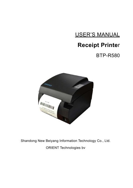
USER’S MANUALReceipt Printer<strong>BTP</strong>-<strong>R580</strong>Shandong New Beiyang Information Technology Co., Ltd.ORIENT Technologies bv
<strong>BTP</strong>-<strong>R580</strong> User’s ManualContentGENERAL SAFETY INSTRUCTION ........................................................................................... 31 INTRODUCTION ..................................................................................................................... 41.1 OUTLINE............................................................................................................................. 41.2 MAIN FEATURES .................................................................................................................. 42 MAIN SPECIFICATION............................................................................................................ 52.1 TECHNICAL SPECIFICATION ................................................................................................... 52.2 CUTTER SPECIFICATION ....................................................................................................... 52.3 PAPER SPECIFICATION ......................................................................................................... 62.3.1 Continuous paper ........................................................................................................ 62.3.2 Marked paper .............................................................................................................. 62.4 PRINT AND CUT POSITION...................................................................................................... 72.4.1 Print position ............................................................................................................... 72.4.2 Cut position................................................................................................................. 73 OUTLINE AND PARTS ............................................................................................................ 83.1 OUTLINE AND PARTS ............................................................................................................ 83.2 ERROR LED AND BUZZERS ................................................................................................... 94 INSTALLATION......................................................................................................................104.1 UNPACKING........................................................................................................................104.2 PRINTER INSTALLATION........................................................................................................104.3 CONNECTING THE POWER ADAPTER .....................................................................................104.4 CONNECTING INTERFACE CABLE ...........................................................................................114.5 CONNECTING THE CASH DRAWER.........................................................................................114.6 PAPER ROLL LOADING..........................................................................................................114.6.1 Confirm the paper type ...............................................................................................114.6.2 Load/replace a paper roll............................................................................................124.7 PAPER NEAR END POSITION ADJUSTMENT ..............................................................................124.8 SWITCHING ON THE PRINTER AND PRINTING OF SELF-TEST.......................................................134.8.1 Switching on the printer..............................................................................................134.8.2 Printing a self-test page..............................................................................................134.9 SETTING OF PRINTER PARAMETERS AND CONFIGURATION ........................................................135 PRINTER ROUTINE MAINTENANCE .....................................................................................155.1 CLEANING THE PLATEN ........................................................................................................155.2 CLEANING THE MARK SENSORS ............................................................................................155.3 CLEARING OF A PAPER JAM ..................................................................................................156 INTERFACE SIGNAL .............................................................................................................166.1 PARALLEL INTERFACE..........................................................................................................166.2 SERIAL INTERFACE..............................................................................................................176.3 USB INTERFACE .................................................................................................................171
<strong>BTP</strong>-<strong>R580</strong> User’s Manual6.4 ETHERNET INTERFACE.........................................................................................................176.5 WLAN INTERFACE ..............................................................................................................186.6 SIGNAL DEFINITION OF POWER CONNECTOR...........................................................................196.7 SIGNAL DEFINITION OF CASH DRAWER INTERFACE...................................................................197 TROUBLESHOOTING ............................................................................................................207.1 PRINTER DOESN’T WORK .....................................................................................................207.2 ALARM LED AND BUZZER SOUND ..........................................................................................207.3 PROBLEMS WITH PRINTING...................................................................................................207.4 CUTTER RESETTING ............................................................................................................208. ACCESSORIES.....................................................................................................................218.1HERALD – KITCHEN ALARM SYSTEM .....................................................................................21APPENDIX A: FEED BUTTON CONFIGURATION .....................................................................212
Declarations<strong>BTP</strong>-<strong>R580</strong> User’s ManualIf you need this manual, please comply with the Clause as below.If you disagree with it, please return this manual immediately.This manual contains the private confidential information belonging to ORIENT Technologies bv(hereinafter referred to as “ORIENT Technologies”) and Shandong New Beiyang Info-Tech Co.,Ltd. (hereinafter referred to as SNBC). You must keep its relative content as the confidentialinformation. If the users are commercial customers or entities, you should be aware to discloseit to those people with the confidential responsibility including your employees, agencies andpartners. When you terminate the cooperation with ORIENT Technologies and SNBC or bringabout your request, you have to stop using this manual and return it to ORIENT Technologies orSNBC, or destroy the confidential information.If any relative organ such as court, arbitrator or government authority requests you to discloseany confidential information of this manual, you must inform ORIENT Technologies or SNBCquickly and also agree that you shall cooperate or assist with ORIENT Technologies or SNBCreasonably during the negotiation.ORIENT Technologies or SNBC has the right to disclose its confidential information and doesnot be responsible for the loss or damages caused from the wrong usage or reference of thismanual by users.Information in this document is subject to change without notice, which is only used for productmaintenance or service relative to this manual. ORIENT Technologies and SNBC reserves theright to improve products as new technology, components, software, and firmware becomeavailable. If users need further data about the products, please feel free to contact ORIENTTechnologies or SNBC.No part of this document may be reproduced or transmitted in any form or by any means,electronic or mechanical, for any purpose without the express written permission of ORIENTTechnologies or SNBC.CopyrightCopyright© 2008 by SNBCPrinted in ChinaTrademarksOur registered trademarks are1
<strong>BTP</strong>-<strong>R580</strong> User’s ManualWarnings and Cautions in this manualWarning: Items shall be strictly followed to avoid damages to body and equipment.Caution: Items with important information and prompts for operating the printer.CertificationsThe quality control system of SNBC has been approved of the following certification.(DNV)ISO9001:2000The environmental control system of SNBC has been approved of the following certification.(DNV)ISO14001:2004Contact usIn CHINA:Address: No.169 Huoju Rd, Weihai, Shandong, China. 264209Hot line: +86-631-5673777Fax: +86-631-5673778E-mail: sales@newbeiyang.comWebsite: www.newbeiyang.com (via Contact button)In EUROPE: ORIENT Technologies bvAddress: Meerheide 115, 5521 DX Eersel, The NetherlandsHot line: +31-497-331080Fax: +31-497-386430Website: www.orient-technologies.com (via Contact button)2
2 Main Specification<strong>BTP</strong>-<strong>R580</strong> User’s Manual2.1 Technical SpecificationItemParameterPrint MethodResolutionPrint WidthPrint SpeedDirect Thermal203DPI (H) ×203DPI (V)80mm (Max.)230mm/s (Max.)Memory RAM: 2MB FLASH: 2MB/4MBDriversInterfaceCash drawerBarcode <strong>Support</strong>edFontsCharacter ModificationImage processPaper near endPaper endLabelTop cover positionPrint head temperaturePaper typePaper widthPaper roll ODPaper cutInputWindows drivers (WIN98/NT/2000/XP/Vista)Optional Parallel(IEEE1248), Serial (RS232C/RS485), USB, Ethernet, WLAN1~2 drivesUPC-A, UPC-E, EAN8, EAN13, CODABAR, CODE39, ITF, CODE128,CODE93,PDF417Font A: 12×24; Font B:9×17; GB2312; GB18030, Korean, Japanese, TraditionalChineseRotate (0°, 90°, 180°, 270°), enlarges(1-6X), emphasize, underline, white/blackreverseRAM bitmap download: buffer size is 12KBFLASH bitmap download: buffer size is 256KBDirect bitmap print: support bitmap and execute quick printOptical sensorOptical sensorOptical sensorMicroswitchThermistorContinuous paper, marked paper82.5 ± 0.5mm, 80 ± 0.5mm, 57.5 ± 0.5mmØ100 mm (Max.)Tear off, Full cut, Partial cut100~240VAC, 50~60HZOutput 24V±5% DC, 2.3APrinter head lifetimeCutter lifetime≥150Km(with reference paper)2,000,000 cuts (Paper type:F240AC/F220-VP)Operation condition 5 ℃ ~45 ℃ , 20%~90% RH (40 ℃ )Storage condition -40 ℃ ~60 ℃ , 20%~93%RH ( 40 ℃ )DimensionsWeight147 (W) × 205 (D) × 147 (H) mmApprox.1.6Kg2.2 Cutter SpecificationItem parameter NoteCutter typeSlide cutter (Guillotine type)5
<strong>BTP</strong>-<strong>R580</strong> User’s ManualCutting time 600ms The time that one cut takesCutting interval 2s 30 times/min. (Max.)Thermal paper or paper with thePaper type0.06~0.1mmsame thicknessOperation voltage24VDCMax. static curren 1.2A 24VDCCutter lifetime2,000,000 cuts (reference paper withthickness of 0.06 mm)Full or partial cuts• Full cut: Cut off the paper completely;• Partial cut: 2 mm paper left in middle2.3 Paper Specification2.3.1 Continuous paper• Paper type:Continuous thermal paper• Paper supply method: Paper roll• Paper width: 82.5±0.5mm,80±0.5mm, 57.5±0.5 mm• Paper thickness:0.06mm-0.1mm• Thermal senstive layer: Outside• Paper roll specificationsOD(MAX):ID(Min):ф100 mmф15mmCaution: Do not paste the paper to the core. If the paper is contaminated by a chemical or oil, it may discolor or lose heat sensitivityat the polluted spot. Do not rub the paper surface strongly against hard objects, otherwise it may discolor. When the temperature goes up to 70 degrees centigrade, paper will discolor. Don’t use or store paper under high temperature, high humidity and strong lightconditions.2.3.2 Marked paperIn marked paper mode, <strong>BTP</strong>-<strong>R580</strong> determines the cut position and the initial printing position byreferencing the position of the black mark. Black marked paper should meet the followingrequirement besides that of standard paper.• L 1 Mark length: 3mm≤L 1 ≤10mm.• L2 Mark length: L 2 ≥12mm.• L3 Distance between marks: 20mm≤L 3
<strong>BTP</strong>-<strong>R580</strong> User’s ManualCaution:The printer will measure the marks during the printing or feeding process. If the lengths ofthe mark (L1) is larger than the default value (default: 13mm), the printer will give apaper-end alarm.2.4 Print and cut position2.4.1 Print position• L1 Paper holder width: 83.5+0/-0.5mm• L2 Max Print width: 80mm• L3: Distance between left end of printhead and left side of paper holder(Fixed) 1.8±0.3mm• L4: Distance between right end of printhead and right side of paper holder(Fixed) 1.8±0.3mm• L5: Left margin (default:7mm)• L6: Print area width. Can set by command (See Programming manual), default is 64mm.• L7: Right margin (default: 9mm)2.4.2 Cut positionL1: about: 30mm L2: about: 11mm7
3 Outline and Parts<strong>BTP</strong>-<strong>R580</strong> User’s Manual3.1 Outline and Parts1—Paper near end sensor adjusting lever2 —Paper holder3 —Platen roller4—Middle cover5—Bottom cover6 — Power switch7—Paper guide8—Top cover9 — Cover spanner10—Printhead11—Paper roll shaft12—Printhead support plate13 —Power connector14 —Communicate interface15 —Cash drawer connectorFunctions of parts:a) Paper guideRemoving the paper guide or putting it in a different slot will allow the printer to use differentpaper widths listed as follows: 82.5±0.5 mm, 80.5±0.5 mm, 57.5±0.5 mm.b) Power switchSwitching the power of the printer on or off. “O” power is turned off. “—” power is turned on.c) Feed button (See Fig 3.1-3)Switching on the printer while pressing the FEED button will start the printingof the configuration table。‣ In normal status:Continuous paper mode:• The printer will feed one line when pressing the FEED button for ashort time.• The printer will feed continuously when pressing the FEED button for a longer timeMarked paper mode:• The printer will feed one line when pressing the FEED button for a short time.• The printer will locate the marks when pressing the FEED button for a longer time.‣ In error status, the printer will have no activity when the FEED button is pressed.d) Power IndicatorIndicating power status (ON/OFF).8
<strong>BTP</strong>-<strong>R580</strong> User’s Manuale) Error indicatorIndicating some error status. Under normal conditions, ERROR LED is always off. Undersome error conditions(Cover Open、Cutter Error、Print head is overheating、Input voltage isabnormal), ERROR LED will flash.f) Paper indicatorIndicating paper status. Under normal conditions, PAPER LED is always off. When the paperstatus changes (paper end or paper near end), PAPER LED will flash.g) Paper end sensorThe paper-end sensor is used to detect whether the paper roll is out of paper.Notices:The paper guide is an indispensable part of the printer and should be kept with the printer.3.2 Error LED and Buzzers1) Error LEDLed Status DescriptionPower Indicator (Green) (POWER)Error Indicator (Red) (ERROR)Paper Indicator (Red) (PAPER)2) Description of LED and Error StatusOnOffOffFlashOnFlashOffPrinter is powered onPrinter is powered offPrinter is in normal status(except paper end or paper near end)Printer is in error statusPrinter Paper is normalMacro definition is runningPrinter is in normal statusError information ERROR LED PAPER LED BuzzerPrint head is overheating Six times Off Long-Short-LongInput voltage is abnormal Five times Off Short-Short-LongCutter Error Four times Off Long-Short-LongCover Is Open Three times Off Short-Long-ShortPaper End Twice On Short-Short-ShortPaper near end Off OnFinding mark error or verify failed Flashing continuously OffCaution: The temperature of the print-head is detected by means of a thermistor sensor. If thetemperature of the printhead becomes higher than 65 0 C, the protection circuit of theprinter will force the printer to stop printing.9
4 Installation<strong>BTP</strong>-<strong>R580</strong> User’s Manual4.1 UnpackingCheck whether all items, that are listed on the packing list are present and in a good condition.If any items are damaged or missing, please contact your dealer.4.2 Printer installation1) The printer should be installed on a flat and stable horizontal surface.2) The printers should be away from any water source.3) Do not place the printer on a surface exposed to vibration or risk from impact.4) Ensure that the printers can be grounded safely.5) During operation and maintenance of the printer there should be sufficient space around theprinter in accordance with the dimensions as shown in fig. 4.2-1.4.3 Connecting the Power Adapter1) Ensure the printer power is turned off.2)Insert the power cord into the power socket on the backside of the printer.3)Fix the power cable cord in the printer with a clip as shown in Fig. 4.3-1.Caution:When connecting or disconnecting the power cord, always hold the plug and avoid draggingit by force.Do not pull on the power cord, otherwise the cord may be damaged or broken, causing a risk10
<strong>BTP</strong>-<strong>R580</strong> User’s Manualof fire or electric shock.Do not place the power cord near a heating device, otherwise, the cover of the cord maymelt, causing a risk of fire or electric shock.If the printer is not in use for a long period, disconnect the power cord from the wall outletfor safety.4.4 Connecting interface cable1) Ensure the printer power is turned off.2) Connect the suitable interface cable with the correct connector to the connector of theinterface board of the printer plug screws (Serial interface) or clip springs (Parallel interface).3) Connect the other end of the interface cable to the host.4.5 Connecting the Cash Drawer1)Ensure the printer power is turned off.2) Insert the cash drawer cable into the cash drawer connector on the back of the printer.Caution: Cash drawer interface can be connected only with a cash drawer device (Do not connecta telephone line and so on).4.6 Paper roll loading4.6.1 Confirm the paper typeAfter connecting of the printer to the mains voltage, with the host and, if applicable, to the cashdrawer, the paper can be loaded and printed.11
4.6.2 Load/replace a paper roll1) Press the latch of the top cover and open it.<strong>BTP</strong>-<strong>R580</strong> User’s Manual2) Place a paper roll in the paper holder.3) Close the printer top cover.Caution: If needed remove the paper guide. Choose the suitable paper guide position according to thewidth of the paper roll and mount the paper guide. When inserting the paper roll pay attentionto the paper path direction.Note: Without paper guide: 82.5±0.5mm.Paper guide in the slot A: 80±0.5mmPaper guide in the slot B: 57.5±0.5mmEnsure that the paper is rolled tightly onto the paper roll, otherwise a paper jam or other faultcould happen.The paper roll should be placed straight in the paper holder and not at an angle. The paperroll should be able to move freely.4.7 Paper near end position adjustmentThrough adjustment of the latch of the paper near end sensor to a corresponding level, different12
<strong>BTP</strong>-<strong>R580</strong> User’s Manualpaper roll cores can be accommodated and also the remaining paper-end length can beapproximated.Caution:The factory setting of the paper near end sensor is level 1.1) When using different Diameter core shaft, C diameter may be different with the length of theremaining paper at the same level.4.8 Switching on the printer and printing of self-test4.8.1 Switching on the printer1) Ensure that the printer is connected to the mains voltage and, if applicable, that the mainsvoltage is switched on.2) Switch on the power of the printer.4.8.2 Printing a self-test page1) Confirm that the printer is connected to the mains voltage and that a paper roll is in theprinter.2) Confirm that the printer is switched off.3) Press down the FEED button while switching on the printer, the printer will start printing theconfiguration sheet. At the end of the configuration sheet the followings text will appear:“Press feed key to continue” The printer is holding and waiting for the input while the PAPERLED is flashing.4) Press down the FEED button shortly, the printer will print a character test page which is partof the self-test.4.9 Setting of printer parameters and configurationThe parameters of the printer can be set (configuring) in a detailed way by means of the utilitysoftware that is available from the reseller or from ORIENT Technologies by special request13
<strong>BTP</strong>-<strong>R580</strong> User’s Manual(website: www.orient-technologies.com. press button “Contact”). However, the majority of theparameters can also be set by using the special key-stroke procedures of the printer. Theseprocedures are simple, do not involve a laptop but only the FEED button on the key-pad of theprinter. The parameters that can be set by pressing the Feed button include:‣ For the serial interface only: setting of baud rate, parity, data bits, stop bits, handshaking,buffer size and data receive error.‣ For all interfaces:• setting of mechanism (mark sensor, cutter, buzzer, power adapter)• print setting (darkness, paper roll width, left margin, right margin, CR command,code page)• Paper sensor setting (paper low alarm, paper end stop)• Set default configurationTo start the key-stroke procedure start the self-test procedure as described in chapter 4.8 steps1 through 3. After the printer has stopped printing the configuration sheet, press and hold theFEED button until the printer starts printing. The printer will print first the Main Menu of thekey-stroke procedure.A more detailed overview of all parameters can be found in Appendix A of this manual.14
5 Printer routine maintenance<strong>BTP</strong>-<strong>R580</strong> User’s ManualCaution: Before starting routine maintenance, ensure that the printer is switched off. Do not use solvents like gasoline or acetone. When cleaning sensors, the printer should not be switched on until the pure alcohol hastotally evaporated. It is recommended that the maintenance cycle should not be longer than one month.5.1 Cleaning the platenThe steps for cleaning the platen are as given below:1) Switch off the printer.2) Open the top cover of the printer.3) When the top cover is opened, wipe off stain such as dust on the platen by using a soft cottoncloth with neutral cleaning agent.4) Close the top cover after the alcohol has evaporated completely.5.2 Cleaning the mark sensorsThe black mark sensors need to be cleaned if the printer has trouble identifying the black marks.The steps for cleaning sensors are as below:1) Switch off the printer.2) Open the top cover of the printer.3) Wipe off stain or dust from the surface of sensors by using a soft cotton swipe impregnatedwith pure alcohol.4) Close the top cover of the printer after the alcohol has evaporated completely.5.3 Clearing of a paper jamRemove the paper, if one of the following phenomena occurs:• The printer fails to feed out paper normally.• Paper is feeding with load noise.The steps for removing paper are as below:1) Switch off the printer.2) Open the top cover of the printer.3) If the paper is jammed in the paper path, remove the wrinkled or wasted part of the paper roll.4) Close the printer top cover.15
6 Interface signal<strong>BTP</strong>-<strong>R580</strong> User’s Manual6.1 Parallel interfaceParallel interface can work in IEEE 1284 compatible mode or half-byte mode, which is a 36 pinsocket.The Interface is defined as below:Pin# Signal source Signal definition1 H NStrobe2 H Data 0 (Least Significant Bit)3 H Data 14 H Data 25 H Data 36 H Data 47 H Data 58 H Data 69 H Data 7 (Most Significant Bit)10 P NAck11 P Busy12 P Perror13 P Select14 H nAutoFd15 Not defined16 Logic Gnd17 Chassis Gnd18 P Peripheral Logic High19 Signal Ground (nStrobe)20 Signal Ground (Data 1)21 Signal Ground (Data 2)22 Signal Ground (Data 3)23 Signal Ground (Data 4)24 Signal Ground (Data 5)25 Signal Ground (Data 6)26 Signal Ground (Data 7)27 Signal Ground (Data 8)28 Signal Ground (PError, Select, and nAck)29 Signal Ground (Busy and nFault)30 Signal Ground (nAutoFd, nSelctIn, and nInit)31 H NInit32 P NFault33 Not defined34 Not defined35 Not defined36 H nSelectIn16
<strong>BTP</strong>-<strong>R580</strong> User’s Manual6.2 Serial interfaceThe serial interface of the printer is compatible with RS-232 and is equipped with a 25-pin femaleD type connector.PIN No.Signal definitionPIN1Frame GroundPIN2TXDPIN 3RXDPIN 4DTRPIN 5Not connectedPIN6DSRPIN 7Signal GroundPIN 8~19Not connectedPIN 20DTRPIN 21~25Not connectedThe user may check the current setting status of the interface by printing a configuration table.The default setting is as follows:Baud rate: 19200bps, 8 data bit, none Parity, 1 stop bitHandshake: DTR/DSR6.3 USB interface‣ ParametersData transmission: <strong>Support</strong> USB1.1 protocolConnector (Printer side): USB B type socket. <strong>Support</strong> and pass USB HUB‣ Interface signal definition and functionsPin No. Signal Description1 VBUS +5V2 DATA- Printer data transmit line minus3 DATA+ Printer data transmit line plus4 GND Ground‣ Interface connector6.4 Ethernet interface‣ Feature• <strong>Support</strong>s 10BASE-T communication• Compatible with Ethernet II standard frame type• LEDs indicate network connecting status and data transmission status.17
<strong>BTP</strong>-<strong>R580</strong> User’s Manual• <strong>Support</strong>s 9100 port print• <strong>Support</strong>s ASB(Auto status back)• <strong>Support</strong>s parameter configuration• <strong>Support</strong>s firmware program updated online• <strong>Support</strong>s printer status query and interface module maintenance based on HTTP.‣ Interface signal definitionThe parameters of Ethernet interface socket match 10BASE-T standard of IEEE802.3. Theinterface signal is defined as below:6.5 WLAN interfacePin Signal name Description1 TX+ Data sending+2 TX- Data sending-3 RX+ Data reception+4 NCReserve5 NC Reserve6 RX- Data reception-7 NC Reserve8 NC Reserve‣ Features• <strong>Support</strong>s 802.11b、802.11g communication• <strong>Support</strong>s 9100 port print and LPR print• <strong>Support</strong>s ASB (Auto Status Back)• <strong>Support</strong>s parameter configuration• <strong>Support</strong>s firmware program upgraded online• <strong>Support</strong>s HTTP‣ Protocols are supported as below• IP• ARP• ICMP• TCP• UDP• DHCP• TFTP• HTTPWLAN interface uses wireless USB network card of which the main specification should berequested from the local distributor or manufacture.18
<strong>BTP</strong>-<strong>R580</strong> User’s Manual6.6 Signal definition of power connectorInternal signal definition of powerPinSignal name1 E2 L3 N6.7 Signal definition of cash drawer interface1) Electric characteristics‣ Driving voltage: DC 24 V‣ Driving current: Max. current is 1 A‣ The signal for checking cash drawer status:“L” = 0~0.5 V “H” = 3.3 V2) Cash drawer interface socket uses RJ-11 6P connector.3) Interface signal definitionNo. Signal Functions1 FG Frame2 DRAWER 1 Driving signal of cash drawer13Check signal for cash drawerDRSWstatus4 VDR Cash drawer driving power5 - NC6 GND Common port with circuitCaution: Do not allow disconnection or connection of the interface cable plug when the printer andthe host are switched on. Avoid the presence of devices like motors with large power as these may cause voltagefluctuations. Always use shielded interface cables.19
7 Troubleshooting<strong>BTP</strong>-<strong>R580</strong> User’s ManualRefer to this section if the printer has any problems.If the problem cannot be solved, please consult with ORIENT Technologies or your supplier..7.1 Printer doesn’t workFaults Possible reasons SolutionPrinter is offConnect the printer powerPower LED is off and the printer doesn’t work Printer is offTurn on the printerCircuit board is damagedContact ORIENT or yoursupplier7.2 Alarm LED and buzzer soundFaults Possible reasons SolutionPaper LED on and buzzer sounds Paper end Replace with new paper rollPaper LED on Paper near end Replace with new paper rollInput voltage is abnormalTurn off the printer power and checkThe input voltageAlarm LED flashes and buzzersoundsPrint head is overheatedTurn off the printer power and wait for theprint head temperature recovered normallyCutter Error Cutter resetting(reference 7.4)Cover is OpenSerious fault occursClose the cover againContact your dealer7.3 Problems with printingFaults Possible reasons SolutionPrintout is light Print head is damaged Replace print headPrintout is not clear or has dirt Print head or platen is dirty Clean print head or platenPaper cannot be fed out properly7.4 Cutter resettingPaper jamOpen top cover and check paper path toremove paper jamIf the moving blade of the cutter does not return to its home-position, then the top cover shouldbe opened and the printer should be switched on. This will force the moving blade to reset andreturn to its home-position. Please contact ORIENT Technologies or your supplier if the problempersists.20
8. Accessories<strong>BTP</strong>-<strong>R580</strong> User’s Manual8.1HERALD – kitchen alarm system1) FunctionsThe Herald is connected to the cash drawer connector of the printer. When the printer sendsCash drawer signal, the Herald will give sound and light signals.2) Light and sound signal mode• There are three levels of light signals:First level: flash;Second level: always light;Third level: not light.• There are three levels of sound signals:First level: sound 1;Second level: sound 2;Third level: sound 3.3)<strong>Support</strong>ed firmwareThe firmware version supporting the Herald should be above FV1.000. All interfaces support thisfunction.4)External connection sketch map.HeraldFig 8.1-1 External connection sketch mapAPPENDIX A: FEED button ConfigurationParameter setting (configuring) by Feed button1) Hold the FEED button pressed while switching the printer on.2) After the printer has printed the configuration sheet, press and hold the FEED button toconfigure the printer. The main menu for the key-stroke setting procedure is printed.3) The procedure consists of several sub-menus and step-by-step working is needed.4) With every choice is a number. This number indicates the number of times the FEED buttonhas to be shortly pressed. After this, the choice is validated by an additional, but longer pressof the FEED button (1 sec).5) After all settings have been done, they are stored in the printer by stepping back throughthe submenus to the main menu by using the number “1” plus additional press for validation.21
‣ Parameter setting by Feed button<strong>BTP</strong>-<strong>R580</strong> User’s ManualMain MenuSelect submenuExitPrint Self TestConfigurationCutter TestSensor Test> 1> 2> 3>4> 5‣ Setting configuration of the printerConfigurationExitwithoutSaveExit withSaveCommunicationMech. &HardwarePrintSettingsPaperSensorSettingSetDefaultConfig> 1> 2>3>4> 5> 6>722
‣ Configuration of the serial interface<strong>BTP</strong>-<strong>R580</strong> User’s ManualCommunicationBackto lastmenu>1BaudRates(default:19200 bps)>2Choices:9600 bps19200 bps38400 bps57600 bps4800 bps2400 bps1200 bps115200 bpsParity(default:none)‣3Choices:NoneOddEvenDataBits(default:8 bits)‣4Choices:7 Bits8 BitsStopBit(s)(default:1 Bit)‣5Choices:1 Bit2 BitsHandshaking(default:DTR/DSR)‣6Choices:DTR/DSRXON/XOFFRx BufferSize(default:4k bytes)‣7Choice:4k bytes45 bytesDataReceiveError(default:ignored)‣8Choices:IgnoredPrint “?”23
‣ Setting Mechanism and Hardware<strong>BTP</strong>-<strong>R580</strong> User’s ManualMech. &HardwareBack tolast menuMarkSensor(default:disabled)Cutter(default:enabled)Buzzer(default:enabled)PowerSupply(default:normal)>1>2>3>4>5Choices:EnabledDisabledChoices:EnabledDisabledChoices:EnabledDisabledChoices:NormalLow powermode24
<strong>BTP</strong>-<strong>R580</strong> User’s Manual‣ Print SettingPrint SettingBack tolastmenu>1Darkness(default:normal)>2Choices:LowNormalHighExtra highPaperRollWidth(default:80 mm)>3Choices:57.5 mm80.0 mm82.5 mmLeftMargin(default:7 mm)>4Choices:0 mm1 mm3 mm5 mm7 mm9 mmRightMargin(default:9 mm)>5Choices:0 mm1 mm3 mm5 mm7 mm9 mmCRCommand(default:disabled)>6Choices:EnabledDisabledCodePage(default:PC 437)>7Choices:PC 437PC 850PC 852PC857PC 858PC 860PC 863PC 865PC 866PC1251PC 1252PC1257Katakana25
<strong>BTP</strong>-<strong>R580</strong> User’s Manual‣ Paper Near-end Sensor settingPaper sensor settingsBack to last menu>1Paper Low Alarm(default: enabled)>2Choices:EnabledDisabledStop print when paper low(default: disabled)>3Choices:EnabledDisabled26
‣ Set Default Configuration<strong>BTP</strong>-<strong>R580</strong> User’s ManualSet default configBack to last Menu>1Set printer to default config>2Choices:EnabledDisabled27