

The GRC-9 Part 2… - VMARSmanuals
The GRC-9 Part 2… - VMARSmanuals
The GRC-9 Part 2… - VMARSmanuals

Create successful ePaper yourself
Turn your PDF publications into a flip-book with our unique Google optimized e-Paper software.
<strong>The</strong> VMARS Newsletter Issue 33<br />
it as much on CW (though phone is fine) or b) make A Simplified Power Supply<br />
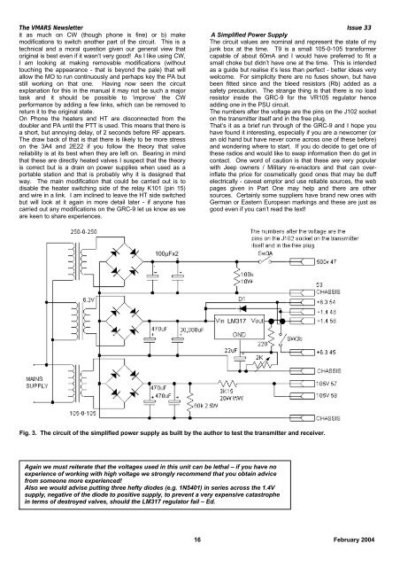
modifications to switch another part of the circuit. This is a <strong>The</strong> circuit values are nominal and represent the state of my<br />
technical and a moral question given our general view that junk box at the time. T9 is a small 105-0-105 transformer<br />
original is best even if it wasn’t very good! As I like using CW, capable of about 60mA and I would have preferred to fit a<br />
I am looking at making removable modifications (without small choke but didn’t have one at the time. This is intended<br />
touching the appearance - that is beyond the pale) that will as a guide but realise it’s less than perfect - better ideas very<br />
allow the MO to run continuously and perhaps key the PA but welcome. For simplicity there are no fuses shown, but have<br />
still working on that one. Having now seen the circuit been fitted since and the bleed resistors (Rb) added as a<br />
explanation for this in the manual it may not be such a major safety precaution. <strong>The</strong> strange thing is that there is no load<br />
task and it should be possible to ‘improve’ the CW resistor inside the <strong>GRC</strong>-9 for the VR105 regulator hence<br />
performance by adding a few links, which can be removed to adding one in the PSU circuit.<br />
return it to the original state.<br />
<strong>The</strong> numbers after the voltage are the pins on the J102 socket<br />
On Phone the heaters and HT are disconnected from the on the transmitter itself and in the free plug.<br />
doubler and PA until the PTT is used. This means that there is That’s it as a brief run through of the <strong>GRC</strong>-9 and I hope you<br />
a short, but annoying delay, of 2 seconds before RF appears. have found it interesting, especially if you are a newcomer (or<br />
<strong>The</strong> draw back of that is that there is likely to be more stress an old hand but have never come across one of these before)<br />
on the 3A4 and 2E22 if you follow the theory that valve and wondering where to start. If you do decide to get one of<br />
reliability is at its best when they are left on. Bearing in mind these radios and would like to swap information then do get in<br />
that these are directly heated valves I suspect that the theory contact. One word of caution is that these are very popular<br />
is correct but is a drain on power supplies when used as a with Jeep owners / Military re-enactors and that can overinflate<br />
portable station and that is probably why it is designed that<br />
the price for cosmetically good ones that may be duff<br />
way. <strong>The</strong> main modification that could be carried out is to electrically - caveat emptor and use reliable sources, the web<br />
disable the heater switching side of the relay K101 (pin 15) pages given in <strong>Part</strong> One may help and there are other<br />
and wire in a link. I am inclined to leave the HT side switched sources. Certainly some suppliers have brand new ones with<br />
but will look at it again in more detail later - if anyone has German or Eastern European markings and these are just as<br />
carried out any modifications on the <strong>GRC</strong>-9 let us know as we good even if you can’t read the text!<br />
are keen to share experiences.<br />
100µFx2<br />
LM317<br />
Fig. 3. <strong>The</strong> circuit of the simplified power supply as built by the author to test the transmitter and receiver.<br />
Again we must reiterate that the voltages used in this unit can be lethal – if you have no<br />
experience of working with high voltage we strongly recommend that you obtain advice<br />
from someone more experienced!<br />
Also we would advise putting three hefty diodes (e.g. 1N5401) in series across the 1.4V<br />
supply, negative of the diode to positive supply, to prevent a very expensive catastrophe<br />
in terms of destroyed valves, should the LM317 regulator fail – Ed.<br />
16 February 2004


