model g0645 benchtop mortising machine - Grizzly Industrial Inc.
model g0645 benchtop mortising machine - Grizzly Industrial Inc.
model g0645 benchtop mortising machine - Grizzly Industrial Inc.
You also want an ePaper? Increase the reach of your titles
YUMPU automatically turns print PDFs into web optimized ePapers that Google loves.
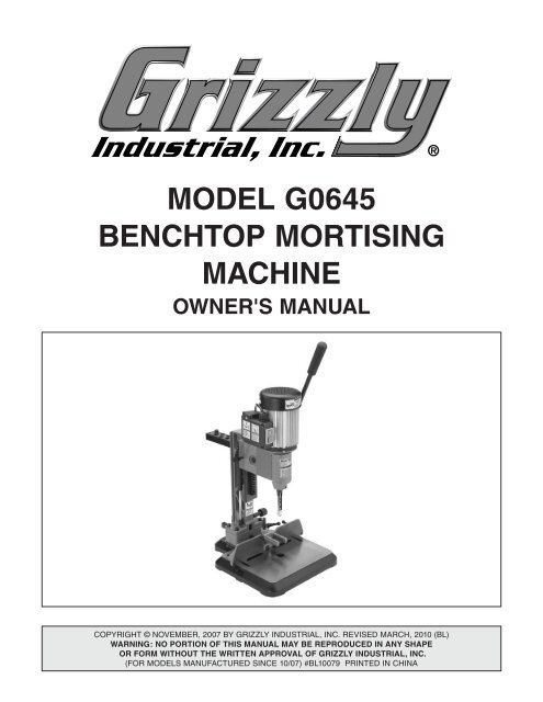
MODEL G0645<br />
BENCHTOP MORTISING<br />
MACHINE<br />
OWNER'S Manual<br />
Copyright © NOVEMBER, 2007 By <strong>Grizzly</strong> <strong>Industrial</strong>, <strong>Inc</strong>. revised march, 2010 (BL)<br />
Warning: No portion of this manual may be reproduced in any shape<br />
Or form without the written approval of <strong>Grizzly</strong> <strong>Industrial</strong>, inc.<br />
(For <strong>model</strong>s manufactured since 10/07) #BL10079 printed in CHINA
Table of Contents<br />
INTRODUCTION................................................ 2<br />
Foreword........................................................ 2<br />
Contact Info.................................................... 2<br />
Machine Data Sheet....................................... 3<br />
Identification................................................... 5<br />
SECTION 1: SAFETY........................................ 6<br />
Safety Instructions for Machinery................... 6<br />
Additional Safety for Mortising Machines....... 8<br />
SECTION 2: CIRCUIT REQUIREMENTS......... 9<br />
110V Operation.............................................. 9<br />
SECTION 3: SETUP........................................ 10<br />
Setup Safety................................................. 10<br />
Items Needed for Setup............................... 10<br />
Unpacking..................................................... 10<br />
Inventory....................................................... 11<br />
Hardware Recognition Chart........................ 12<br />
Clean Up...................................................... 13<br />
Site Considerations...................................... 13<br />
Mounting....................................................... 14<br />
Assembly...................................................... 14<br />
Test Run....................................................... 16<br />
SECTION 4: OPERATIONS............................ 17<br />
Operation Safety.......................................... 17<br />
Basic Operations.......................................... 17<br />
Basic Controls.............................................. 17<br />
Installing Mortising Chisel............................. 18<br />
Adjusting Depth Stop Rod............................ 19<br />
Adjusting Fence............................................ 20<br />
Hold Down.................................................... 20<br />
Basic Mortising Operations.......................... 21<br />
Rotating Column........................................... 22<br />
SECTION 5: ACCESSORIES.......................... 23<br />
SECTION 6: MAINTENANCE......................... 24<br />
Schedule....................................................... 24<br />
Cleaning....................................................... 24<br />
Unpainted Cast Iron..................................... 24<br />
Drill Bits & Mortising Chisels........................ 24<br />
SECTION 7: SERVICE.................................... 25<br />
Troubleshooting............................................ 25<br />
Adjusting Gibs.............................................. 26<br />
Replacing Gas Spring.................................. 26<br />
Electrical Components & Wiring Diagram.... 27<br />
Parts Breakdown.......................................... 28<br />
Parts List...................................................... 29<br />
Label Placement........................................... 29<br />
WARRANTY AND RETURNS......................... 33
INTRODUCTION<br />
Foreword<br />
Contact Info<br />
We are proud to offer the Model G0645 Benchtop<br />
Mortising Machine. This <strong>machine</strong> is part of a growing<br />
<strong>Grizzly</strong> family of fine woodworking <strong>machine</strong>ry.<br />
When used according to the guidelines set forth in<br />
this manual, you can expect years of trouble-free,<br />
enjoyable operation and proof of <strong>Grizzly</strong>’s commitment<br />
to customer satisfaction.<br />
The specifications, drawings, and photographs<br />
illustrated in this manual represent the Model<br />
G0645 when the manual was prepared. However,<br />
owing to <strong>Grizzly</strong>’s policy of continuous improvement,<br />
changes may be made at any time with no<br />
obligation on the part of <strong>Grizzly</strong>.<br />
For your convenience, we always keep current<br />
<strong>Grizzly</strong> manuals available on our website at www.<br />
grizzly.com. Any updates to your <strong>machine</strong> will be<br />
reflected in these manuals as soon as they are<br />
complete. Visit our site often to check for the latest<br />
updates to this manual!<br />
If you have any comments regarding this manual,<br />
please write to us at the address below:<br />
<strong>Grizzly</strong> <strong>Industrial</strong>, <strong>Inc</strong>.<br />
C<br />
/O Technical Documentation Manager<br />
P.O. Box 2069<br />
Bellingham, WA 98227-2069<br />
Email: manuals@grizzly.com<br />
We stand behind our <strong>machine</strong>s. If you have any<br />
service questions or parts requests, please call or<br />
write us at the location listed below.<br />
<strong>Grizzly</strong> <strong>Industrial</strong>, <strong>Inc</strong>.<br />
1203 Lycoming Mall Circle<br />
Muncy, PA 17756<br />
Phone: (570) 546-9663<br />
Fax: (800) 438-5901<br />
E-Mail: techsupport@grizzly.com<br />
Web Site: http://www.grizzly.com<br />
-2- Model G0645 (Mfg. since 10/07)
Machine Data Sheet<br />
MACHINE DATA<br />
SHEET<br />
Customer Service #: (570) 546-9663 · To Order Call: (800) 523-4777 · Fax #: (800) 438-5901<br />
MODEL G0645 1/2 HP BENCH-TOP MORTISING MACHINE<br />
Product Dimensions:<br />
Weight................................................................................................................................................................ 70 lbs.<br />
Length/Width/Height....................................................................................................................... 29 x 13-3/4 x 32 in.<br />
Foot Print (Length/Width)................................................................................................................. 13-3/4 x 16-1/4 in.<br />
Shipping Dimensions:<br />
Type............................................................................................................................................................. Cardboard<br />
Content............................................................................................................................................................ Machine<br />
Weight................................................................................................................................................................ 76 lbs.<br />
Length/Width/Height............................................................................................................................. 22 x 19 x 17 in.<br />
Electrical:<br />
Motors:<br />
Main<br />
Switch......................................................................................................................................... ON/OFF Push Button<br />
Switch Voltage...................................................................................................................................................... 110V<br />
Cord Length............................................................................................................................................................ 6 ft.<br />
Cord Gauge....................................................................................................................................................18 guage<br />
Minimum Circuit Size........................................................................................................................................ 15 amp<br />
Plug <strong>Inc</strong>luded.......................................................................................................................................................... Yes<br />
Type.................................................................................................................. TEFC Capacitor Start Induction<br />
Horsepower..............................................................................................................................................1/2 HP<br />
Voltage........................................................................................................................................................110V<br />
Prewired......................................................................................................................................................110V<br />
Phase........................................................................................................................................................ Single<br />
Amps...............................................................................................................................................................6A<br />
Speed.................................................................................................................................................1725 RPM<br />
Cycle..........................................................................................................................................................60 Hz<br />
Number Of Speeds........................................................................................................................................... 1<br />
Power Transfer ................................................................................................................................Direct Drive<br />
Bearings........................................................................................................Shielded and Permanently Sealed<br />
Main Specifications:<br />
Operation<br />
Spindle Taper..............................................................................................................................................JT#2<br />
No Of Spindle Speeds.......................................................................................................................................1<br />
Range Of Spindle Speeds..................................................................................................................1725 RPM<br />
Cutting Capacities<br />
Maximum Stock Width........................................................................................................................... 8-1/2 in.<br />
Maximum Stock Thickness...........................................................................................................................6 in.<br />
Maximum Mortising Depth............................................................................................................................3 in.<br />
Maximum Chisel Travel..........................................................................................................................4-5/8 in.<br />
Maximum Dist Column To Chisel................................................................................................................. 5 in.<br />
Chisel Size Range..............................................................................................................1/4, 5/16, 3/8, 1/2 in.<br />
Fence to Chisel Center Distance..................................................................................................................4 in.<br />
Model G0645<br />
The information contained herein is deemed accurate as of 3/26/2010 and represents our most recent product specifications.<br />
Due to our ongoing improvement efforts, this information may not accurately describe items previously purchased. PAGE 1 OF 2<br />
Model G0645 (Mfg. since 10/07) -3-
Table Information<br />
Table Size Length................................................................................................................................ 12-1/4 in.<br />
Table Size Width.................................................................................................................................. 10-1/2 in.<br />
Table Size Thickness............................................................................................................................. 1-3/4 in.<br />
Chuck Information<br />
Chuck Type......................................................................................................................................Keyed-Type<br />
Chuck Size................................................................................................................................................ 3/8 in.<br />
Chuck Capacity......................................................................................................................................... 3/8 in.<br />
Construction<br />
Other<br />
Base..............................................................................................................................................................Iron<br />
Head........................................................................................................................................... Cast Aluminum<br />
Table.....................................................................................................................................................Cast Iron<br />
Paint.......................................................................................................................................................... Epoxy<br />
Column................................................................................................................................................. Cast Iron<br />
Fence....................................................................................................................................................Cast Iron<br />
Handle Length............................................................................................................................................ 16 in.<br />
Head Drive.............................................................................................................................................. Manual<br />
Other Specifications:<br />
Features:<br />
Country Of Origin ................................................................................................................................................China<br />
Warranty ............................................................................................................................................................ 1 Year<br />
Serial Number Location ............................................................................................. ID Label on Center of the Stand<br />
Assembly Time ........................................................................................................................................... 30 minutes<br />
Tool Storage Rack in Back of Column<br />
<strong>Inc</strong>ludes Four Chisels<br />
Dovetail Height Movement<br />
Rack & Pinion Table Movement<br />
<strong>Inc</strong>ludes Riser Block fo Raising Height<br />
Model G0645<br />
The information contained herein is deemed accurate as of 3/26/2010 and represents our most recent product specifications.<br />
Due to our ongoing improvement efforts, this information may not accurately describe items previously purchased. PAGE 2 OF 2<br />
-4- Model G0645 (Mfg. since 10/07)
Identification<br />
K<br />
A<br />
P<br />
J<br />
B<br />
L<br />
I<br />
H<br />
G<br />
C<br />
D<br />
E<br />
F<br />
N<br />
O<br />
M<br />
Figure 1. Model G0645 features.<br />
A. Tool Storage Rack<br />
B. Chuck Access Cover<br />
C. Chisel and Drill Bit Set<br />
D. Hold Down Lock Lever<br />
E. Fence<br />
F. Base<br />
G. Fence Lock Lever<br />
H. Extension Block<br />
I. Gas Spring<br />
J. Depth Stop Lock Lever<br />
K. Hand Lever<br />
L. Column<br />
M. Fence Adjustment Knob<br />
N. Hold Down<br />
O. Depth Stop Rod<br />
P. ON/OFF Switch<br />
Model G0645 (Mfg. since 10/07) -5-
SECTION 1: SAFETY<br />
For Your Own Safety, Read Instruction<br />
Manual Before Operating this Machine<br />
The purpose of safety symbols is to attract your attention to possible hazardous conditions. This<br />
manual uses a series of symbols and signal words intended to convey the level of importance<br />
of the safety messages. The progression of symbols is described below. Remember that safety<br />
messages by themselves do not eliminate danger and are not a substitute for proper accident<br />
prevention measures.<br />
Indicates an imminently hazardous situation which, if not avoided,<br />
WILL result in death or serious injury.<br />
Indicates a potentially hazardous situation which, if not avoided,<br />
COULD result in death or serious injury.<br />
Indicates a potentially hazardous situation which, if not avoided,<br />
MAY result in minor or moderate injury. It may also be used to alert<br />
against unsafe practices.<br />
NOTICE<br />
Safety Instructions for Machinery<br />
This symbol is used to alert the user to useful information about<br />
proper operation of the <strong>machine</strong>.<br />
Safety Instructions for Machinery<br />
1. READ ENTIRE MANUAL BEFORE<br />
STARTING. operating <strong>machine</strong> before<br />
reading the manual greatly increases the<br />
risk of injury.<br />
2. ALWAYS USE ANSI APPROVED<br />
SAFETY GLASSES WHEN OPERATING<br />
MACHINERY. Everyday eyeglasses only<br />
have impact resistant lenses —they are<br />
Not safety glasses.<br />
3. ALWAYS WEAR A NIOSH APPROVED<br />
RESPIRATOR WHEN OPERATING<br />
MACHINERY THAT PRODUCES DUST.<br />
Most types of dust (wood, metal, etc.) can<br />
cause severe respiratory illnesses.<br />
4. ALWAYS USE HEARING PROTECTION<br />
WHEN OPERATING MACHINERY.<br />
Machinery noise can cause permanent<br />
hearing loss.<br />
5. WEAR PROPER APPAREL. do Not<br />
wear loose clothing, gloves, neckties, rings,<br />
or jewelry that can catch in moving parts.<br />
Wear protective hair covering to contain<br />
long hair and wear non-slip footwear.<br />
6. NEVER OPERATE MACHINERY WHEN<br />
TIRED OR UNDER THE INFLUENCE OF<br />
DRUGS OR ALCOHOL. Be mentally alert<br />
at all times when running <strong>machine</strong>ry.<br />
-6- Model G0645 (Mfg. since 10/07)
Safety Instructions for Machinery<br />
7. ONLY ALLOW TRAINED AND PROP-<br />
ERLY SUPERVISED PERSONNEL TO<br />
OPERATE MACHINERY. Make sure<br />
operation instructions are safe and clearly<br />
understood.<br />
8. KEEP CHILDREN/VISITORS AWAY.<br />
Keep all children and visitors away from<br />
<strong>machine</strong>ry. When <strong>machine</strong> is not in use,<br />
disconnect it from power, lock it out, or<br />
disable the switch to make it difficult for<br />
unauthorized people to start the <strong>machine</strong>.<br />
9. UNATTENDED OPERATION. leaving<br />
<strong>machine</strong> unattended while its running<br />
greatly increases the risk of an accident or<br />
property damage. turn <strong>machine</strong> OFF and<br />
allow all moving parts to come to a complete<br />
stop before walking away.<br />
10. DO NOT USE IN DANGEROUS<br />
ENVIRONMENTS. do Not use <strong>machine</strong>ry<br />
in damp, wet locations, or where any<br />
flammable or noxious fumes may exist.<br />
11. KEEP WORK AREA CLEAN AND WELL<br />
LIGHTED. Clutter and dark shadows may<br />
cause accidents.<br />
12. USE A GROUNDED POWER SUPPLY<br />
RATED FOR THE MACHINE AMPERAGE.<br />
grounded cords minimize shock hazards.<br />
operating <strong>machine</strong> on an incorrect size of<br />
circuit increases risk of fire.<br />
13. ALWAYS DISCONNECT FROM POWER<br />
SOURCE BEFORE SERVICING<br />
MACHINERY. Make sure switch is in oFF<br />
position before reconnecting.<br />
14. MAINTAIN MACHINERY WITH CARE.<br />
Keep blades sharp and clean for best and<br />
safest performance. Follow instructions for<br />
lubricating and changing accessories.<br />
15. MAKE SURE GUARDS ARE IN PLACE<br />
AND WORK CORRECTLY BEFORE<br />
USING MACHINERY.<br />
16. REMOVE CHUCK KEYS OR ADJUSTING<br />
TOOLS. Make a habit of never leaving<br />
chuck keys or other adjustment tools in/on<br />
the <strong>machine</strong>—especially near spindles!<br />
17. DAMAGED MACHINERY. Check for binding<br />
or misaligned parts, broken parts,<br />
loose bolts, other conditions that may<br />
impair <strong>machine</strong> operation. always repair or<br />
replace damaged parts before operation.<br />
18. DO NOT FORCE MACHINERY. Work at<br />
the speed for which the <strong>machine</strong> or accessory<br />
was designed.<br />
19. SECURE WORKPIECE. use clamps or<br />
a vise to hold the workpiece when practical.<br />
a secured workpiece protects your<br />
hands and frees both hands to operate the<br />
<strong>machine</strong>.<br />
20. DO NOT OVERREACH. Maintain stability<br />
and balance at all times when operating<br />
<strong>machine</strong>.<br />
21. MANY MACHINES CAN EJECT<br />
WORKPIECES TOWARD OPERATOR.<br />
Know and avoid conditions that cause the<br />
workpiece to "kickback."<br />
22. STABLE MACHINE. Machines that move<br />
during operations greatly increase the<br />
risk of injury and loss of control. Verify<br />
<strong>machine</strong>s are stable/secure and mobile<br />
bases (if used) are locked before starting.<br />
23. CERTAIN DUST MAY BE HAZARDOUS<br />
to the respiratory systems of people and<br />
animals, especially fine dust. Be aware of<br />
the type of dust you are exposed to and<br />
always wear a respirator designed to filter<br />
that type of dust.<br />
24. EXPERIENCING DIFFICULTIES. if at<br />
any time you are experiencing difficulties<br />
performing the intended operation, stop<br />
using the <strong>machine</strong>! Contact our technical<br />
support department at (570) 546-9663.<br />
Model G0645 (Mfg. since 10/07) -7-
Additional Safety for Mortising Machines<br />
1. HAND PROTECTION. Do not place your<br />
hands under an installed chisel at any<br />
time or near the chisel while the spindle<br />
is in motion. Chisels may become hot during<br />
operation! Allow chisels to cool before<br />
handling. Chisels are sharp! Always use<br />
caution when handling, especially when<br />
installing or removing.<br />
2. USING CORRECT MATERIALS. Mortising<br />
materials such as metals, plastics, and<br />
glass can result in serious personal injury<br />
and <strong>machine</strong> damage. Do not use the<br />
<strong>machine</strong> for anything except <strong>mortising</strong> in<br />
wood.<br />
3. RESPIRATOR AND SAFETY GLASSES.<br />
Dust and chips created from <strong>mortising</strong> and<br />
may be ejected, becoming hazards to the<br />
eyes and lungs. Always wear a respirator<br />
and safety glasses while operating the<br />
<strong>machine</strong>.<br />
4. CHISEL COMPATIBILITY. Mortising bits<br />
can fly out of chuck at the operator if not<br />
properly secured, causing serious personal<br />
injury. Make sure the <strong>mortising</strong> bit fits a<br />
minimum of 1 /2" into the chuck.<br />
5. ADJUSTMENTS. Hands may be seriously<br />
injured if they come in contact with the<br />
chisel and drill bit during operation. Do not<br />
adjust the <strong>machine</strong> or workpiece while the<br />
<strong>mortising</strong> <strong>machine</strong> is running. Wait for the<br />
spindle to come to a complete stop and<br />
unplug the <strong>machine</strong> before continuing.<br />
6. INSPECTING MACHINE. Loose chisels<br />
and bits can be ejected at the operator,<br />
or the headstock can fall if not properly<br />
secured, causing serious personal injury.<br />
Inspect the <strong>machine</strong> for smooth head casting<br />
movement, loose drill bits/chisel housing,<br />
loose nuts/bolts and lock levers before<br />
connecting the <strong>machine</strong> to power and operating.<br />
Correct any problems before use.<br />
7. EXPERIENCING DIFFICULTIES. If at any<br />
time you are experiencing difficulties performing<br />
the intended operation, stop using<br />
the <strong>machine</strong>! Contact Tech Support at<br />
(570) 546-9663.<br />
Like all <strong>machine</strong>ry there is potential danger<br />
when operating this <strong>machine</strong>. Accidents are<br />
frequently caused by lack of familiarity or<br />
failure to pay attention. Use this <strong>machine</strong><br />
with respect and caution to lessen the possibility<br />
of operator injury. If normal safety<br />
precautions are overlooked or ignored, serious<br />
personal injury may occur.<br />
No list of safety guidelines can be complete.<br />
Every shop environment is different. Always<br />
consider safety first, as it applies to your<br />
individual working conditions. Use this and<br />
other <strong>machine</strong>ry with caution and respect.<br />
Failure to do so could result in serious personal<br />
injury, damage to equipment, or poor<br />
work results.<br />
-8- Model G0645 (Mfg. since 10/07)
SECTION 2: CIRCUIT REQUIREMENTS<br />
110V Operation<br />
Power Connection Device<br />
The Model G0645 comes with a 5-15 plug, similar<br />
to Figure 2, to connect the <strong>machine</strong> to power.<br />
Serious personal injury could occur if you<br />
connect the <strong>machine</strong> to power before completing<br />
the setup process. DO NOT connect<br />
the <strong>machine</strong> to the power until instructed<br />
later in this manual.<br />
grounding prong is<br />
longest of the three<br />
prongs<br />
Electrocution or fire could<br />
result if <strong>machine</strong> is not<br />
grounded and installed in<br />
compliance with electrical<br />
codes. Compliance MUST<br />
be verified by a qualified<br />
electrician!<br />
Current<br />
Carrying prongs<br />
grounded<br />
outlet<br />
Figure 2. Typical 5-15 plug and receptacle.<br />
Full Load Amperage Draw<br />
Motor Draw...............................................6 Amps<br />
Minimum Circuit Requirements<br />
You MUST connect your <strong>machine</strong> to a grounded<br />
circuit that is rated for the amperage given below.<br />
Never replace a circuit breaker on an existing circuit<br />
with one of higher amperage without consulting<br />
a qualified electrician to ensure compliance<br />
with wiring codes. If you are unsure about the<br />
wiring codes in your area or you plan to connect<br />
your <strong>machine</strong> to a shared circuit, consult<br />
a qualified electrician.<br />
110V Circuit...........................................15 Amps<br />
This <strong>machine</strong> MUST have a ground prong in<br />
the plug to help ensure that it is grounded.<br />
DO NOT remove ground prong from plug<br />
to fit into a two-pronged outlet! If the plug<br />
will not fit the outlet, have the proper outlet<br />
installed by a qualified electrician.<br />
Extension Cords<br />
We do not recommend using extension cords, but<br />
if you find it absolutely necessary:<br />
• Use at least a 14 gauge cord that does not<br />
exceed 50 feet in length!<br />
• The extension cord must have a ground wire<br />
and plug pin.<br />
• A qualified electrician MUST size cords over<br />
50 feet long to prevent motor damage.<br />
Model G0645 (Mfg. since 10/07) -9-
SECTION 3: SETUP<br />
Setup Safety<br />
This <strong>machine</strong> presents<br />
serious injury hazards<br />
to untrained users. Read<br />
through this entire manual<br />
to become familiar with<br />
the controls and operations<br />
before starting the<br />
<strong>machine</strong>!<br />
Wear safety glasses during<br />
the entire setup process!<br />
This <strong>machine</strong> and its<br />
components are heavy.<br />
Get lifting help to move<br />
heavy items.<br />
Items Needed for<br />
Setup<br />
The following items are needed to complete the<br />
setup process, but are not included with your<br />
<strong>machine</strong>:<br />
Description<br />
Qty<br />
• Safety Glasses (for each person)............... 1<br />
• Mounting Hardware ................... As Needed<br />
• Shop Rags for Cleaning.............. As Needed<br />
• Solvent Cleaner/Degreaser......... As Needed<br />
• Assistant for Lifting Help............................. 1<br />
• Flat Head Screwdriver................................ 1<br />
• Phillips Head Screwdriver........................... 1<br />
• Wrench/Socket 13mm<br />
(optional, for extension block)..................... 1<br />
Unpacking<br />
Your <strong>machine</strong> was carefully packaged for safe<br />
transportation. Remove the packaging materials<br />
from around your <strong>machine</strong> and inspect it. If you<br />
discover the <strong>machine</strong> is damaged, please immediately<br />
call Customer Service at (570) 546-9663<br />
for advice.<br />
Save the containers and all packing materials for<br />
possible inspection by the carrier or its agent.<br />
Otherwise, filing a freight claim can be difficult.<br />
When you are completely satisfied with the condition<br />
of your shipment, inventory the contents.<br />
-10- Model G0645 (Mfg. since 10/07)
Inventory<br />
A<br />
The following is a description of the main components<br />
shipped with your <strong>machine</strong>. Lay the components<br />
out to inventory them.<br />
Note: If you can't find an item on this list, check<br />
the mounting location on the <strong>machine</strong> or examine<br />
the packaging materials carefully. Occasionally<br />
we pre-install certain components for shipping<br />
purposes.<br />
Box 1: (Figure 3)<br />
Qty<br />
A. Hand Lever.................................................. 1<br />
B. Gas Spring.................................................. 1<br />
C. Tool Storage Rack...................................... 1<br />
D. Hold Down.................................................. 1<br />
E. Mortising Chisel and Bit 1 ⁄4"......................... 1<br />
F. Mortising Chisel and Bit 5 ⁄16"....................... 1<br />
G. Mortising Chisel and Bit 3 ⁄8"......................... 1<br />
H. Mortising Chisel and Bit 1 ⁄2"......................... 1<br />
I. Extension Block.......................................... 1<br />
J. Hardware & Tools (Not Shown)................. 1<br />
— Chuck Key/ Hex Wrench 4mm............... 1<br />
— Hex Wrenches 4, 8 mm................. 1 Each<br />
— Hex Bolts M8-1.25 x 80 (Extension)....... 4<br />
— Flat Washers 6mm (Storage Rack)........ 2<br />
— Long Hold Down Rod (Extension).......... 1<br />
B<br />
C<br />
D<br />
E<br />
F<br />
G<br />
Figure 3. G0645 inventory.<br />
If any nonproprietary parts are missing (e.g. a<br />
nut or a washer), we will gladly replace them; or<br />
for the sake of expediency, replacements can be<br />
obtained at your local hardware store.<br />
H<br />
SUFFOCATION HAZARD!<br />
Immediately discard all plastic<br />
bags and packing materials<br />
to eliminate choking/suffocation<br />
hazards for children<br />
and animals.<br />
I<br />
Model G0645 (Mfg. since 10/07) -11-
Hardware Recognition Chart<br />
-12- Model G0645 (Mfg. since 10/07)
Clean Up<br />
The unpainted surfaces are coated with a waxy<br />
oil to prevent corrosion during shipment. Remove<br />
this protective coating with a solvent cleaner or<br />
citrus-based degreaser such as <strong>Grizzly</strong>’s G7895<br />
Citrus Degreaser. To clean thoroughly, some parts<br />
must be removed. For optimum performance<br />
from your <strong>machine</strong>, clean all moving parts or<br />
sliding contact surfaces. Avoid chlorine-based<br />
solvents, such as acetone or brake parts cleaner<br />
that may damage painted surfaces. Always follow<br />
the manufacturer’s instructions when using any<br />
type of cleaning product.<br />
Gasoline and petroleum<br />
products have low flash<br />
points and can explode<br />
or cause fire if used to<br />
clean <strong>machine</strong>ry. DO<br />
NOT use these products<br />
to clean the <strong>machine</strong>ry.<br />
Many cleaning solvents<br />
are toxic if inhaled.<br />
Minimize your risk by only<br />
using these products in a<br />
well ventilated area.<br />
G7895—<strong>Grizzly</strong> Citrus Degreaser<br />
This natural, citrus-based degreaser is a great<br />
solution for removing export grease, and it’s much<br />
safer to work around than nasty solvents.<br />
Site Considerations<br />
Workbench Load<br />
Refer to the Machine Data Sheet for the weight<br />
and footprint specifications of your <strong>machine</strong>.<br />
Some workbenches may require additional reinforcement<br />
to support both the <strong>machine</strong> and the<br />
workpiece.<br />
Placement Location<br />
Consider existing and anticipated needs, size of<br />
material to be processed through each <strong>machine</strong>,<br />
and space for auxiliary stands, work tables or<br />
other <strong>machine</strong>ry when establishing a location for<br />
your new <strong>machine</strong>. See Figure 5 for the minimum<br />
working clearances. The workbench should be<br />
located where plenty of working clearance exists<br />
for larger workpieces.<br />
25"<br />
16 1 /4"<br />
110V<br />
<br />
13 3 /4"<br />
- Machine dimensions<br />
29"<br />
- Footprint<br />
Figure 5. Minimum working clearances.<br />
Children and visitors may be<br />
seriously injured if unsupervised<br />
around this <strong>machine</strong>.<br />
Lock entrances to the shop<br />
or disable start switch or<br />
power connection to prevent<br />
unsupervised use.<br />
Figure 4. <strong>Grizzly</strong> citrus degreaser.<br />
Model G0645 (Mfg. since 10/07) -13-
Mounting<br />
Assembly<br />
Mount the <strong>mortising</strong> <strong>machine</strong> to a workbench<br />
through the two holes in the base.<br />
The strongest mounting option is a "Through<br />
Mount" where holes are drilled all the way through<br />
the workbench, and hex bolts, washers, and hex<br />
nuts are used to secure the <strong>mortising</strong> <strong>machine</strong> to<br />
the workbench.<br />
Bolt<br />
The included extension block will extend the column<br />
an additional 1 3 ⁄4", so workpieces up to 6"<br />
thick can be mortised. You will not be able to use<br />
the fence adjustment knob when the extension<br />
block is installed. If you do not want to install the<br />
extension block, skip Steps 6-10.<br />
To assemble the Model G0645:<br />
1. Secure the handle onto the hub using the<br />
spring and shoulder bolt already attached to<br />
the headstock, as shown in Figure 8.<br />
<br />
<br />
Flat Washer<br />
Flat Washer<br />
lock Washer<br />
hex Nut<br />
Hand Lever<br />
Hub<br />
Figure 6. Example of a through mount setup.<br />
Another option for mounting is a "Direct Mount"<br />
where the <strong>machine</strong> is simply secured to the workbench<br />
with a lag screw.<br />
lag screw<br />
Flat Washer<br />
Shoulder<br />
Bolt<br />
Spring<br />
Figure 8. Hand lever installed.<br />
2. Loosen the lock lever and insert the depth<br />
stop rod into the hole on the headstock, as<br />
shown in Figure 9.<br />
Depth<br />
Stop<br />
Rod<br />
<br />
<br />
Figure 7. Example of a direct mount setup.<br />
Lock Lever<br />
Figure 9. Depth stop rod installed.<br />
-14- Model G0645 (Mfg. since 10/07)
3. Lift the headstock to the top position using<br />
the hand lever. Position the depth stop so it<br />
contacts the top of the headstock, as shown<br />
in Figure 10, and secure the lock knob so the<br />
headstock does not move.<br />
Depth Stop<br />
Ball Stud<br />
Figure 12. Gas spring attached to bottom of<br />
column.<br />
5. Install the tool storage rack, as shown in<br />
Figure 13, with the M6-1 x 15 Phillips head<br />
screws and flat washers already attached to<br />
the headstock.<br />
Figure 10. Depth stop contacting headstock.<br />
4. Snap the gas spring ball sockets onto the ball<br />
studs, as shown in Figures 11 & 12.<br />
Tip: It may help to use a flat head screwdriver<br />
to leverage the bottom gas spring ball socket<br />
onto the ball stud.<br />
Figure 13. Tool storage rack installed.<br />
The headstock must be locked in place<br />
before the gas spring is installed. Serious<br />
personal injury can occur if the headstock<br />
drops during installation.<br />
CRUSHING HAZARD!<br />
Have an assistant hold the headstock during<br />
the following step. The headstock is heavy<br />
and could cause serious personal injury if<br />
not supported.<br />
6. Remove the four M8-1.25 x 25 hex bolts,<br />
flat washers and lock washers securing the<br />
column to the base, shown in Figure 14, and<br />
temporarily lay the headstock on its side on<br />
the workbench.<br />
Ball Stud<br />
Figure 11. Gas spring attached to top of<br />
headstock.<br />
Figure 14. Hex bolts and washers securing<br />
column to base.<br />
Model G0645 (Mfg. since 10/07) -15-
7. Place the extension block over the rack and<br />
base, and align the mounting holes, as shown<br />
in Figure 15.<br />
Test Run<br />
Extension Block<br />
Rack<br />
Once the assembly is complete, test run your<br />
<strong>machine</strong>.<br />
If, during the test run, you cannot easily locate<br />
the source of an unusual noise or vibration, stop<br />
using the <strong>machine</strong> immediately, then review the<br />
Troubleshooting on Page 25.<br />
If you still cannot remedy a problem, contact our<br />
Tech Support at (570) 546-9663 for assistance.<br />
Figure 15. Extension block positioned on base.<br />
8. Place the column over the extension block,<br />
align the mounting holes, have an assistant<br />
hold the headstock upright, and secure the<br />
column to the base with the M8-1.25 x 80 hex<br />
bolts and the washers removed in Step 6, as<br />
shown in Figure 16.<br />
To test run the <strong>machine</strong>:<br />
1. Make sure you have read the safety instructions<br />
at the beginning of the manual and that<br />
the <strong>machine</strong> is setup properly.<br />
2. Verify that there is not a drill bit or chisel<br />
installed, and that all tools are cleared away<br />
from the <strong>machine</strong>.<br />
3. Connect the <strong>machine</strong> to the power source.<br />
4. Turn the <strong>machine</strong> ON.<br />
5. Listen to and watch for abnormal noises or<br />
actions. The <strong>machine</strong> should run smoothly<br />
with little or no vibration or rubbing noises.<br />
Figure 16. Extension block installed.<br />
9. Remove the hold down, loosen the set screw<br />
securing the short hold down rod, and remove<br />
the rod.<br />
— Strange or unusual noises should be investigated<br />
and corrected before operating the<br />
<strong>machine</strong> further. Always disconnect the<br />
<strong>machine</strong> from power when investigating or<br />
correcting potential problems.<br />
6. Turn the <strong>machine</strong> OFF.<br />
10. Insert the long hold down rod into the shaft<br />
on the fence, secure with the set screw, and<br />
reinstall the hold down.<br />
-16- Model G0645 (Mfg. since 10/07)
SECTION 4: OPERATIONS<br />
Operation Safety<br />
Basic Controls<br />
Damage to your eyes and lungs could result<br />
from using this <strong>machine</strong> without proper protective<br />
gear. Always wear safety glasses and<br />
a respirator when operating this <strong>machine</strong>.<br />
Below is a summary of the basic controls used<br />
during <strong>mortising</strong> operations. Use the list with<br />
Figure 17 to become familiar with your <strong>mortising</strong><br />
<strong>machine</strong>.<br />
ON/OFF Switch: Starts or stops motor.<br />
Depth Stop Rod: Controls the mortise depth.<br />
Hand Lever: Raises or lowers headstock.<br />
Fence Lock Handles: Locks fence. When loosened,<br />
allows fence to move.<br />
Never mortise treated lumber—the smoke is<br />
extremely poisonous.<br />
NOTICE<br />
If you have never used this type of <strong>machine</strong><br />
or equipment before, We strongly recommend<br />
that you read books, trade magazines,<br />
or get formal training before beginning<br />
any projects. Regardless of the content<br />
in this section, <strong>Grizzly</strong> <strong>Industrial</strong> will<br />
not be held liable for accidents caused by<br />
lack of training.<br />
Fence Adjustment Knob: Moves fence back and<br />
forth on the table—is disabled when the extension<br />
block is installed.<br />
Hold Down Lock Lever: Locks hold down.<br />
Hold Down: Holds workpiece down when chisel<br />
is raised after mortise is cut.<br />
ON/OFF<br />
Switch<br />
Hand<br />
Lever<br />
Basic Operations<br />
This <strong>machine</strong> uses a hollow chisel with a drill bit to<br />
cut square holes called mortises. After setting the<br />
fence, depth stop, and hold down, use the hand<br />
lever to lower the chisel and bit into the workpiece,<br />
then raise the hand lever to remove the chisel and<br />
bit from the workpiece.<br />
Depth Stop<br />
Rod<br />
Fence Lock<br />
Handle<br />
Hold Down<br />
Fence<br />
Adjustment<br />
Knob<br />
Hold Down<br />
Lock Lever<br />
Figure 17. Model G0645 basic controls.<br />
Model G0645 (Mfg. since 10/07) -17-
Installing Mortising<br />
Chisel<br />
This <strong>mortising</strong> <strong>machine</strong> uses 5 ⁄8" shank chisels<br />
ranging from 1 ⁄4"– 1 ⁄2". If you want to use chisels<br />
that did not come with this <strong>machine</strong>, make sure<br />
they conform to the dimensions in the Figure 18.<br />
4. Slide the bit into the chisel and loosen the<br />
chisel lock set screw (Figure 19) on the<br />
headstock.<br />
5. Insert the chisel into the bushing shown in<br />
Figure 19, and tighten the chisel lock set<br />
screw.<br />
A<br />
Chuck<br />
C<br />
B Lock Set<br />
Screw<br />
Bushing<br />
Bit<br />
5<br />
/8" Max. Dia.<br />
3" Cut Depth<br />
Chisel<br />
1<br />
⁄2" Minimum Chuck Grab<br />
Chisel<br />
Min.<br />
Overall<br />
Bit<br />
Length<br />
(A)<br />
Max<br />
Drill Bit<br />
Dia.<br />
(B)<br />
Min.<br />
Overall<br />
Chisel<br />
Length<br />
(C)<br />
1<br />
⁄4" 6 1 ⁄4"<br />
11<br />
⁄64" 4 1 ⁄4"<br />
5<br />
⁄16" 6 1 ⁄4" 7<br />
⁄32" 4 1 ⁄4"<br />
Figure 19. Inserting chisel into bushing.<br />
6. Open the chuck access cover.<br />
7. Using the chuck key, tighten the drill bit into<br />
the drill chuck so the tip extends 1 ⁄16"— 3 ⁄16"<br />
beyond the chisel, as shown in Figure 20.<br />
The correct distance depends on the wood<br />
type and operation.<br />
3<br />
⁄8" 7 5 ⁄16"<br />
17<br />
⁄64" 5 1 ⁄2"<br />
1<br />
⁄2" 7 5 ⁄16" 3<br />
⁄8" 5 1 ⁄2"<br />
Figure 18. G0645 chisel and drill bit dimensions.<br />
To install a <strong>mortising</strong> chisel:<br />
1. DISCONNECT THE MORTISING MACHINE<br />
FROM POWER!<br />
2. Lock the headstock in the fully raised position.<br />
3. Put on a pair of leather gloves to protect<br />
your hands, or wrap a shop towel around the<br />
sharp end of the chisel. Place a wood scrap<br />
on the table to protect it during chisel and bit<br />
installation.<br />
Wrong<br />
1<br />
⁄16– 3 ⁄16"<br />
Correct<br />
Figure 20. Drill bit extension.<br />
8. Rotate the chuck by hand and make sure no<br />
binding occurs.<br />
—If binding occurs, loosen the chisel lock set<br />
screw and rotate the chisel 90°.<br />
-18- Model G0645 (Mfg. since 10/07)
9. Place a square against the fence and chisel,<br />
as shown in Figure 21, to verify that the<br />
chisel is square to the fence.<br />
Adjusting Depth<br />
Stop Rod<br />
When adjusted correctly, the depth stop rod<br />
ensures that the mortise is not cut too deep and<br />
repeated mortise depths are consistent. Always<br />
make the mortise at least an 1 ⁄8" deeper than the<br />
tenon to allow room for excess glue.<br />
To adjust the depth stop rod:<br />
1. Loosen the depth lock lever, lower the chisel<br />
until it contacts the top of the workpiece.<br />
Figure 21. Squaring chisel to fence.<br />
— If the chisel is not square to the fence,<br />
loosen the chisel lock set screw, twist the<br />
chisel into alignment, then tighten the set<br />
screw.<br />
2. Adjust the depth stop using one of the methods<br />
below:<br />
• Adjust the depth stop rod above the column<br />
to the desired depth of the mortise cut,<br />
using a ruler, as shown in Figure 22 and<br />
then tighten the lock lever.<br />
10. Close the chuck access door and carefully<br />
tighten the fence lock handles, making sure<br />
the fence does not move.<br />
— If the fence does move, repeat Steps 7 &<br />
8.<br />
Figure 22. Adjusting depth stop using ruler.<br />
• Another method of setting the depth stop is<br />
to mark the depth of the mortise cut on the<br />
side or front of the workpiece with a pencil,<br />
lower the bottom of the chisel to the line,<br />
as shown in Figure 23, then lock the depth<br />
stop.<br />
Depth Mark<br />
Figure 23. Depth marked on workpiece.<br />
Model G0645 (Mfg. since 10/07) -19-
Adjusting Fence<br />
The fence can be moved back and forth on the<br />
table by loosening the spring-loaded lock levers,<br />
rotating the fence adjustment knob, and tightening<br />
the lock levers (Figure 24).<br />
Hold<br />
Down<br />
Lock<br />
Lever<br />
Note: The fence adjustment knob cannot be used<br />
when the extension block is installed.<br />
Fence<br />
Adjustment<br />
Knob<br />
Figure 25. Low hold down position.<br />
The hold down may also be placed directly on<br />
the workpiece when making multiple mortises.<br />
However, each time you cut a mortise you<br />
will have to loosen the lock knob, move the<br />
workpiece, and then secure the hold down.<br />
Lock<br />
Levers<br />
You can also flip the hold down to hold thicker<br />
workpieces, as shown in Figure 26.<br />
Figure 24. Fence controls.<br />
Hold Down<br />
The hold down acts as a clamp, holding the<br />
workpiece to the table surface. The hold down<br />
must be used to keep the workpiece from raising<br />
when the chisel is removed after a cut.<br />
To use the hold down:<br />
1. Position the chisel over the workpiece and<br />
lock the depth stop rod.<br />
Figure 26. High hold down position.<br />
2. Loosen the hold down rod lock lever, adjust<br />
the bottom of the hold down 1 /16" above the<br />
top of the workpiece—allowing the workpiece<br />
to move horizontally for making multiple mortises,<br />
then secure the lock lever, as shown in<br />
Figure 25.<br />
When placed in the position shown in Figure<br />
25, the bracket will hold down a workpiece<br />
slightly taller than the fence.<br />
-20- Model G0645 (Mfg. since 10/07)
Basic Mortising<br />
Operations<br />
To make a basic mortise:<br />
1. DISCONNECT THE MORTISING MACHINE<br />
FROM POWER!<br />
2. Verify that the chisel and fence are square<br />
(see Installing Chisel, Page 18) and adjust<br />
as needed.<br />
3. Secure the fence lock handles, place a piece<br />
of scrap lumber the same dimensions as the<br />
workpiece flush with the fence, and set the<br />
depth stop (see Adjusting Depth Stop Rod,<br />
Page 19).<br />
HAND INJURY HAZARD!<br />
During the next step, keep fingers and hands<br />
away from chisel and drill bit path when cutting<br />
the mortise.<br />
4. Layout the desired mortise on the test piece.<br />
5. Position and lock the hold down.<br />
6. Align the chisel with the mortise outline (see<br />
Figure 27), turn the power ON, and use the<br />
hand lever to steadily feed the <strong>mortising</strong><br />
chisel into the test piece.<br />
Pulling down on the handle can be difficult<br />
on some woods. However, NEVER use<br />
a cheater pipe or handle extender on the<br />
handle. You could break the hand lever and<br />
be seriously injured.<br />
—The feed rate must be fast enough to<br />
prevent the tip of the bit from burning, but<br />
slow enough to prevent the motor from<br />
stalling. This speed will vary depending on<br />
the wood type, moisture content, and frequency<br />
of chip clearing from the mortise.<br />
—When cutting deep mortises, make a 1"<br />
deep cut, then back off and allow the chips<br />
to clear before cutting deeper.<br />
Note: Some chisel noise and smoke is<br />
normal, but we recommend using a small<br />
amount of lubrication on the drill bit (not the<br />
chisel) to keep this to a minimum. See Page<br />
24 for more information on lubricating the drill<br />
bit.<br />
7. When the desired depth is achieved, move<br />
the hand lever back to the upper position.<br />
The test piece should remain in place as this<br />
is done.<br />
8. Turn the power OFF.<br />
9. Check the placement of the hole on the test<br />
piece, and adjust the fence if necessary.<br />
When the desired accuracy of placement is<br />
achieved, repeat Steps 4-8 on the actual<br />
workpiece.<br />
10. When making rectangular mortises, follow<br />
the sequence of cuts shown in Figure 28.<br />
Position the chisel over the center of cuts<br />
5, 6 and 7, since these only use part of the<br />
chisel.<br />
1 5 2 6 3 7 4<br />
Figure 27. Aligning chisel with outline.<br />
Figure 28. Sequence of cuts.<br />
Model G0645 (Mfg. since 10/07) -21-
Rotating Column<br />
The head and column assembly can be adjusted<br />
for <strong>mortising</strong> off of the base—this will allow<br />
the <strong>mortising</strong> <strong>machine</strong> to accommodate a taller<br />
workpiece.<br />
6. Remount the column to the base with the hex<br />
bolts and washers removed earlier, as shown<br />
in Figure 29.<br />
To rotate the column 180°:<br />
1. With assistance, remove the four hex bolts<br />
and washers securing the column to the<br />
base, and set the column and headstock<br />
aside.<br />
2. Remove the hardware mounting the base to<br />
the workbench.<br />
3. Remove the fence lock levers and the fence.<br />
4. Place the back of the base flush with workbench<br />
edge and remount the base with the<br />
hardware removed earlier.<br />
5. If used, rotate the fence and extension block<br />
180°, and place them on the base.<br />
Figure 29. Column rotated 180° for larger<br />
workpiece.<br />
7. Place the workpiece flush against the fence<br />
and secure with a clamp, as shown in Figure<br />
29.<br />
8. Reverse Steps 1-7 to mount the column and<br />
headstock for normal operation.<br />
-22- Model G0645 (Mfg. since 10/07)
ACCESSORIES<br />
SECTION 5: ACCESSORIES<br />
Using accessories or attachments not recommended<br />
for this <strong>machine</strong> may cause the<br />
<strong>machine</strong> to function differently than intended,<br />
which may increase the risk of serious<br />
personal injury. Only use recommended<br />
accessories for ths <strong>machine</strong>.<br />
G5562—SLIPIT ® 1 Qt. Gel<br />
G5563—SLIPIT ® 12 oz Spray<br />
G2871—Boeshield ® T-9 12 oz Spray<br />
G2870—Boeshield ® T-9 4 oz Spray<br />
H3788—G96 ® Gun Treatment 12 oz Spray<br />
H3789—G96 ® Gun Treatment 4.5 oz Spray<br />
H7583—Tenoning Jig<br />
Use this simple jig on your table saw to make<br />
tenons for a mortise and tenon joint. Precision<br />
adjustments make it easy to create a perfect<br />
tenon every time.<br />
Figure 31. Recommended products for protecting<br />
unpainted cast iron/steel part on <strong>machine</strong>ry.<br />
NOTICE<br />
Refer to the newest copy of the <strong>Grizzly</strong><br />
Catalog for other accessories available for<br />
this <strong>machine</strong>.<br />
Figure 30. Table saw tenoning jig.<br />
Model G0645 (Mfg. since 10/07) -23-
SECTION 6: MAINTENANCE<br />
Always disconnect power<br />
to the <strong>machine</strong> before<br />
performing maintenance.<br />
Failure to do this may<br />
result in serious personal<br />
injury.<br />
Schedule<br />
For optimum performance from your <strong>machine</strong>,<br />
follow this maintenance schedule and refer to any<br />
specific instructions given in this section.<br />
Daily Check:<br />
• Loose mounting bolts.<br />
• Worn switch or damaged wires.<br />
• Any other unsafe condition.<br />
• Worn or damaged chisel or bits.<br />
Cleaning<br />
Unpainted Cast Iron<br />
Protect the unpainted cast iron surfaces on the<br />
table by wiping the table clean after every use—<br />
this ensures moisture from wood dust does not<br />
remain on bare metal surfaces.<br />
Keep tables rust-free with regular applications of<br />
products like G96 ® Gun Treatment, SLIPIT ® , or<br />
Boeshield ® T-9 (see Section 5: Accessories on<br />
Page 23 for more details).<br />
Drill Bits & Mortising<br />
Chisels<br />
The drill bits for <strong>mortising</strong> chisels operate under<br />
extreme conditions. A small amount of bees wax<br />
applied to the drill bit can aid in reducing heat and<br />
expelling chips. It is important that a small amount<br />
is used and none is applied to the chisel. Bees<br />
wax coming into contact with the finished surfaces<br />
will impede adhesion of glues and finishes.<br />
Cleaning the Model G0645 is relatively easy.<br />
Vacuum excess wood chips and sawdust, and<br />
wipe off the remaining dust with a dry cloth. If any<br />
resin has built up, use a resin dissolving cleaner<br />
to remove it. Treat all unpainted cast iron and steel<br />
with a non-staining lubricant after cleaning.<br />
-24- Model G0645 (Mfg. since 10/07)
SECTION 7: SERVICE<br />
Review the troubleshooting and procedures in this section to fix or adjust your <strong>machine</strong> if a problem develops.<br />
If you need replacement parts or you are unsure of your repair skills, then feel free to call our Technical<br />
Support at (570) 546-9663.<br />
Troubleshooting<br />
Motor & Electrical<br />
Symptom Possible Cause Possible Solution<br />
Motor will not start;<br />
fuses or circuit<br />
breakers blow.<br />
1. Tripped breaker.<br />
2. Short circuit in line cord or plug.<br />
3. Open circuit in motor or loose connections.<br />
Motor overheats 1. Short circuit in motor or loose connections.<br />
or stalls (resulting<br />
in blown fuses or<br />
2. Air circulation through the motor restricted.<br />
tripped circuit).<br />
3. <strong>Inc</strong>orrect size fuses or circuit breakers.<br />
4. Motor overloaded.<br />
Loud repetitious<br />
noise coming from<br />
<strong>machine</strong>.<br />
Mortising Operations<br />
1. Repair for cause of tripped breaker and reset.<br />
2. Repair or replace cord or plug for damaged insulation<br />
and shorted wires.<br />
3. Inspect all lead connections on motor for loose or<br />
open connections.<br />
1. Replace motor connections with loose/shorted terminals<br />
or worn insulation.<br />
2. Clean out motor to provide normal air circulation.<br />
3. Install correct fuses or circuit breakers.<br />
4. Reduce load on motor.<br />
1. Motor fan is hitting the cover. 1. Adjust fan cover mounting position, tighten fan, or<br />
shim fan cover.<br />
Symptom Possible Cause Possible Solution<br />
Difficult to pull<br />
1. Adjust the drill bit depth.<br />
lever down during<br />
<strong>machine</strong> operation.<br />
Mortising bit and<br />
chisel are extremely<br />
noisy, chatter, and<br />
smoke. (An average<br />
amount of noise and<br />
chatter are normal<br />
for any <strong>mortising</strong><br />
<strong>machine</strong>.)<br />
Moritising bit and<br />
chisel generate<br />
smoke and burn the<br />
workpiece.<br />
1. Drill bit does not protrude enough from the<br />
end of the chisel.<br />
2. Chisel or drill bit is dull.<br />
3. Mortising operating handle is not positioned<br />
for maximum leverage.<br />
4. Chisel is too big for job.<br />
1. Drill bit out of alignment with chisel.<br />
2. The chisel mounting bushing is loose or<br />
damaged causing poor drill bit-to-chisel<br />
alignment.<br />
3. The chisel or drill bit is bent.<br />
4. Normal condition.<br />
1. The drill bit is dull.<br />
2. Drilling pressure is too aggressive and overheats<br />
the drill bit.<br />
3. Wood chips load up in the chisel and overheat<br />
the drill bit.<br />
4. Wood is too green, has high moisture content,<br />
or is pressure treated.<br />
2. Sharpen/replace drill bit and chisel.<br />
3. Adjust the handle for maximum length, and position<br />
it so you have the maximum leverage at the most<br />
dificult <strong>mortising</strong> depth.<br />
4. Use up to 1 /2" chisel (maximum).<br />
1. Reinstall chisel in a different position.<br />
2. Replace bushing, using care not to over-tighten the<br />
chisel retaining set screw.<br />
3. Replace the chisel and drill bit as a matched set.<br />
4. Some amount of chatter and smoke is normal.<br />
1. Sharpen/replace drill bit and chisel.<br />
2. Adjust drill bit depth, reduce drilling pressure, clear<br />
chips often.<br />
3. Apply small amount of bees wax to drill bit; face<br />
chisel slot sideways; clear chips often.<br />
4. Only mortise dry, untreated wood.<br />
Model G0645 (Mfg. since 10/07) -25-
Adjusting Gibs<br />
Tools Needed:<br />
Qty<br />
6mm Hex Wrench...............................................1<br />
The Model G0645 has a dovetail gib located on<br />
the side of the headstock (Figure 32).<br />
Replacing Gas<br />
Spring<br />
Tools Needed:<br />
Qty<br />
Flat Head Screwdriver.........................................1<br />
When working correctly, the gas spring shown in<br />
Figure 33 keeps the headstock under pressure<br />
so it does not drop when the operating handle is<br />
released. If you ever notice that the gas spring<br />
stops working correctly, then promptly replace it.<br />
To replace the gas spring:<br />
Cap Screws<br />
1. Raise the headstock as far as it will go and<br />
set the depth stop to keep the head from falling.<br />
Adjustment<br />
Screws<br />
Figure 32. Adjustment screws for headstock gib.<br />
The gib controls the accuracy of the sliding parts<br />
and keeps them stable during operation. The goal<br />
of adjusting the gib is to remove unnecessary<br />
play when the slides are moved, without tightening<br />
them so much that they bind. The gib can be<br />
tightened or loosened by using the adjustment<br />
screws.<br />
2. Pull the gas spring off of the ball studs, as<br />
shown in Figure 33.<br />
Tip: Position the flat part of the screwdriver<br />
close to the ball stud on the gas spring as<br />
shown in Figure 34, to prevent snapping the<br />
ball stud off.<br />
Ram<br />
To adjust the gibs:<br />
1. Loosen the cap screws and move the headstock<br />
up or down slowly while turning the<br />
adjustment screws.<br />
2. Tighten the cap screws when you obtain a<br />
snug fit between the column and gib with a<br />
minimal amount of side-to-side movement.<br />
Figure 33. Removing gas spring from ball stud.<br />
(side View)<br />
screwdriver<br />
Ball stud<br />
Figure 34. Correctly leveraging gas spring.<br />
3. Replace the gas spring on the ball studs so<br />
the ram end points down.<br />
-26- Model G0645 (Mfg. since 10/07)
Electrical Components & Wiring Diagram<br />
Neutral<br />
hot<br />
ground<br />
<br />
<br />
<br />
run<br />
Capacitor<br />
30MFd<br />
250VaC<br />
ground<br />
oN<br />
oFF<br />
o<br />
switch<br />
(Viewed<br />
from behind)<br />
Figure 35. G0645 electrical components.<br />
Motor<br />
Model G0645 (Mfg. since 10/07) -27-
Parts Breakdown<br />
65<br />
69<br />
70 68<br />
71<br />
1<br />
1-1<br />
1-3<br />
66<br />
3<br />
2<br />
9<br />
1-2<br />
1-4<br />
72<br />
5<br />
4<br />
10<br />
11 12<br />
64<br />
62<br />
61<br />
6<br />
13 14<br />
15<br />
7<br />
8<br />
28<br />
27<br />
31<br />
30<br />
16 17 18 19 20 21<br />
44<br />
42<br />
44-2<br />
22<br />
57<br />
58<br />
44-1<br />
46<br />
41<br />
40<br />
39<br />
67<br />
42<br />
33<br />
34<br />
35<br />
25<br />
32<br />
24<br />
23<br />
Label Placement<br />
56<br />
55<br />
47<br />
50<br />
51 52<br />
36 37<br />
38<br />
104<br />
102<br />
103<br />
53<br />
101<br />
54<br />
106<br />
105<br />
100<br />
59<br />
60<br />
-28- Model G0645 (Mfg. since 10/07)
Parts List<br />
REF PART # DESCRIPTION REF PART # DESCRIPTION<br />
1 P0645001 MOTOR 1/2 HP 110V 35 PW01M FLAT WASHER 8MM<br />
1-1 P0645001-1 FAN COVER 36 PSS09M SET SCREW M8-1.25 X 20<br />
1-2 P0645001-2 FAN 37 P0645037 GEAR<br />
1-3 P0645001-3 CAPACITOR COVER 38 P0645038 FENCE ADJUSTMENT KNOB<br />
1-4 P0645001-4 R CAPACITOR 25M 300V 2-7/8 X 1-3/8 39 P0645039 RACK<br />
2 P0645002 CHUCK JT#2 0-3/8" 40 PSB28M CAP SCREW M6-1 X 15<br />
3 P0645003 CHUCK KEY/HEX WRENCH 4MM 41 P0645041 ALIGNMENT PIN<br />
4 P0645004 LOCK LEVER M8-1.25 X 20 42 P0645042 BALL END<br />
5 PS07M PHLP HD SCR M4-.7 X 8 44 P0645044 GAS SPRING ASSEMBLY<br />
6 P0645006 CHUCK ACCESS COVER 44-1 P0645044-1 CYLINDER<br />
7 PSS09M SET SCREW M8-1.25 X 20 44-2 P0645044-2 COLUMN ADAPTER<br />
8 P0645008 BUSHING 46 P0645046 LOCK LEVER M8-1.25 X 50<br />
9 P0645009 DEPTH STOP ROD 47 PW01M FLAT WASHER 8MM<br />
10 P0645010 HEADSTOCK 50 P0645050 RACK<br />
11 P0645011 DOVETAIL GIB 51 P0645051 BRACKET<br />
12 PSB14M CAP SCREW M8-1.25 X 20 52 PSS16M SET SCREW M8-1.25 X 10<br />
13 PS39M PHLP HD SCR M8-1.25 X 10 53 PSS09M SET SCREW M8-1.25 X 20<br />
14 P0645014 GEAR 54 P0645054 FENCE<br />
15 P0645015 SPECIAL SCREW 55 PSS16M SET SCREW M8-1.25 X 10<br />
16 P0645016 SPACER 56 P0645056 SHORT HOLD DOWN ROD 104MM<br />
17 P0645017 SHAFT 57 P0645057 HOLD DOWN<br />
18 PRP08M ROLL PIN 6 X 30 58 P0645058 LOCK LEVER M8-1.25 X 20<br />
19 P0645019 CLUTCH 59 P0645059 BASE<br />
20 P0645020 CLUTCH COLLAR 60 PSN03M SQUARE NUT M8-1.25<br />
21 P0645021 COMPRESSION SPRING 61 P0645061 EXTENSION BLOCK<br />
22 P0645022 SHOULDER BOLT M10-1.5 X 15 62 PB82M HEX BOLT M8-1.25 X 80<br />
23 PRP07M ROLL PIN 6 X 20 64 P0645064 LONG HOLD DOWN ROD 145MM<br />
24 P0645024 HANDLE 65 P0645065 POWER CORD 18AWG X 3C<br />
25 P0645025 RUBBER GRIP 66 P0645066 T-HANDLE HEX WRENCH 4MM<br />
27 P0645027 MAGNET 67 PEC07M E-CLIP 7MM<br />
28 PSB24M CAP SCREW M5-.8 X 16 68 P0645068 SWITCH COVER<br />
30 PS11M PHLP HD SCR M6-1 X 16 69 P0645069 SWITCH<br />
31 PW03M FLAT WASHER 6MM 70 PHTEK31M TAP SCREW M4 X 14<br />
32 P0645032 TOOL STORAGE RACK 71 P0645071 STRAIN RELIEF<br />
33 P0645033 COLUMN ASSEMBLY 72 PAW08M HEX WRENCH 8MM<br />
34 PB07M HEX BOLT M8-1.25 X 25<br />
Label Placement<br />
REF PART # DESCRIPTION REF PART # DESCRIPTION<br />
100 P0645100 ID LABEL 104 PLABEL-14 ELECTRICITY LABEL<br />
101 P0645101 SAFETY GLASSES LABEL 2-3/4" X 1-1/2" 105 P0645105 HAND INJURY LABEL 1-1/2" X 2-1/2"<br />
102 P0645102 READ MANUAL LABEL 1-1/2" X 2-1/2" 106 PPAINT-1 GRIZZLY GREEN TOUCH UP PAINT<br />
103 P0645103 DISCONN POWER LABEL 1-1/2" X 2-1/2"<br />
Safety labels warn about <strong>machine</strong> hazards and ways to prevent injury. The owner of this <strong>machine</strong><br />
MUST maintain the original location and readability of the labels on the <strong>machine</strong>. If any label is<br />
removed or becomes unreadable, REPLACE that label before using the <strong>machine</strong> again. Contact<br />
<strong>Grizzly</strong> at (800) 523-4777 or www.grizzly.com to order new labels.<br />
Model G0645 (Mfg. since 10/07) -29-
WARRANTY CARD<br />
<br />
<br />
<br />
<br />
<br />
The following information is given on a voluntary basis. It will be used for marketing purposes to help us develop<br />
better products and services. Of course, all information is strictly confidential.<br />
1. <br />
<br />
<br />
<br />
2. <br />
<br />
<br />
<br />
<br />
<br />
<br />
<br />
<br />
<br />
<br />
<br />
<br />
<br />
<br />
<br />
<br />
<br />
<br />
<br />
<br />
3. <br />
<br />
<br />
4. <br />
<br />
<br />
<br />
<br />
<br />
<br />
<br />
<br />
<br />
5. <br />
<br />
6. <br />
<br />
7. <br />
8. <br />
9. <br />
Note: We never use names more than 3 times. <br />
10. _____________________________________________________________________<br />
_________________________________________________________________________________<br />
_________________________________________________________________________________<br />
_________________________________________________________________________________
WARRANTY AND RETURNS<br />
<strong>Grizzly</strong> <strong>Industrial</strong>, <strong>Inc</strong>. warrants every product it sells for a period of 1 year to the original purchaser from<br />
the date of purchase. This warranty does not apply to defects due directly or indirectly to misuse, abuse,<br />
negligence, accidents, repairs or alterations or lack of maintenance. This is <strong>Grizzly</strong>’s sole written warranty<br />
and any and all warranties that may be implied by law, including any merchantability or fitness, for any particular<br />
purpose, are hereby limited to the duration of this written warranty. We do not warrant or represent<br />
that the merchandise complies with the provisions of any law or acts unless the manufacturer so warrants.<br />
In no event shall <strong>Grizzly</strong>’s liability under this warranty exceed the purchase price paid for the product and<br />
any legal actions brought against <strong>Grizzly</strong> shall be tried in the State of Washington, County of Whatcom.<br />
We shall in no event be liable for death, injuries to persons or property or for incidental, contingent, special,<br />
or consequential damages arising from the use of our products.<br />
To take advantage of this warranty, contact us by mail or phone and give us all the details. We will then<br />
issue you a “Return Number,’’ which must be clearly posted on the outside as well as the inside of the<br />
carton. We will not accept any item back without this number. Proof of purchase must accompany the<br />
merchandise.<br />
The manufacturers reserve the right to change specifications at any time because they constantly strive to<br />
achieve better quality equipment. We make every effort to ensure that our products meet high quality and<br />
durability standards and we hope you never need to use this warranty.<br />
Please feel free to write or call us if you have any questions about the <strong>machine</strong> or the manual.<br />
Thank you again for your business and continued support. We hope to serve you again soon.
Buy Direct and Save with <strong>Grizzly</strong> ® – Trusted, Proven and a Great Value!<br />
~Since 1983~<br />
Visit Our Website Today For<br />
Current Specials!<br />
ORDER<br />
24 HOURS A DAY!<br />
1-800-523-4777


