MODEL 713 - Inovonics
MODEL 713 - Inovonics
MODEL 713 - Inovonics

Create successful ePaper yourself
Turn your PDF publications into a flip-book with our unique Google optimized e-Paper software.
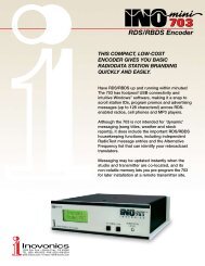
PROGRAMMING AND OPERATION<br />
INSTRUCTION MANUAL<br />
R D S<br />
RADIO DATA SYSTEM<br />
<strong>MODEL</strong> <strong>713</strong><br />
RADIODATA ENCODER<br />
(WITH TCP/IP CONNECTIVITY)
USERS RECORD <br />
Model <strong>713</strong> Serial No. ____________<br />
Date Purchased __________________<br />
Warranty Card Mailed? o<br />
PROGRAMMING AND OPERATION<br />
INSTRUCTION MANUAL<br />
<strong>MODEL</strong> <strong>713</strong><br />
R D S<br />
RADIO DATA SYSTEM<br />
RADIODATA ENCODER<br />
(WITH TCP/IP CONNECTIVITY)<br />
July, 2005<br />
1305 Fair Avenue Santa Cruz, CA 95060<br />
TEL: (831) 458-0552 FAX: (831) 458-0554<br />
Visit our Website: www.inovon.com
TABLE OF CONTENTS<br />
Section I - INTRODUCTION<br />
<strong>MODEL</strong> <strong>713</strong> PRODUCT DESCRIPTION ................................................................... 3<br />
The Radio Data System RDS vs. RBDS General Features<br />
<strong>MODEL</strong> <strong>713</strong> TECHNICAL SPECIFICATIONS ........................................................... 4<br />
BLOCK DIAGRAM ................................................................................................... 5<br />
Section II - THE RADIO DATA SYSTEM<br />
RDS: EUROPE vs. AMERICA ................................................................................... 6<br />
THE RDS SYSTEM .................................................................................................. 6<br />
ADDRESSING THE <strong>MODEL</strong> <strong>713</strong> ENCODER ........................................................... 7<br />
RDS APPLICATIONS SUPPORTED BY THE <strong>MODEL</strong> <strong>713</strong> ....................................... 7<br />
AF DI FFG M/S PI PS PTY RT TA TP<br />
Section III - ENCODER INSTALLATION<br />
UNPACKING AND INSPECTION ........................................................................... 10<br />
MOUNTING ........................................................................................................... 10<br />
Rack Requirement Heat Dissipation<br />
AC (MAINS) POWER ............................................................................................. 10<br />
Fuseholder Mains Voltage Selector Power Cord<br />
RADIO FREQUENCY INTERFERENCE (RFI) ......................................................... 11<br />
Location Ground Loops<br />
SELECTION OF OPERATING MODES .................................................................. 11<br />
Sidechain Mode Loop-Through Mode<br />
CONNECTING THE <strong>MODEL</strong> <strong>713</strong> ........................................................................... 12<br />
Important Connection Considerations Sidechain Mode (preferred)<br />
Loop-Through Mode Manually Activating the TA Flag<br />
DATA INTERCONNECTION ................................................................................... 14<br />
Computer or Terminal Requirements Modem Link<br />
SUBCARRIER INJECTION LEVEL ......................................................................... 16<br />
Setting Subcarrier Amplitude Subcarrier Phase<br />
Section IV - THE WINDOWS ® INTERFACE<br />
PROGRAMMING OPTIONS ................................................................................... 18<br />
Advanced Programming for Station Automation<br />
Simplified Windows ® Data-Entry Software<br />
LOADING AND RUNNING THE SIMPLIFIED WINDOWS ® SOFTWARE ................ 18<br />
Installing the Software<br />
<br />
1
INSTALLING THE USB PORT DRIVER....................................................................19<br />
SERIAL (COM PORT) ENCODER COMMUNICATIONS .........................................21<br />
THE DATA-ENTRY SCREEN ..................................................................................22<br />
Some notes on Dynamic Messaging RDS vs. RBDS Mode<br />
Using ALL-CAPS PI Code Calculator Parsing Defined<br />
Safe Scrolling Explained Sending Data to the Encoder<br />
Reading Data From the Encoder File Management<br />
PROGRAMMING PORT PRIORITIES ......................................................................28<br />
ENCODER FRONT-PANEL INDICATORS ..............................................................28<br />
Section V - TCP/IP CONNECTIVITY<br />
CONFIGURING THE LAN PORT ............................................................................30<br />
Support Software Loading DeviceInstaller<br />
Connecting the Encoder to the Network<br />
Assigning the IP Address Confirming Device Properties<br />
BROWSER NETWORK CONNECTION ...............................................................33<br />
Jave Installation Java Utility Implications Password Protection<br />
USING A VIRTUAL COM PORT............................................................................ 35<br />
Loading the Redirector Program<br />
NETWORK CONNECTION FOR AUTOMATION .....................................................37<br />
Router Considerations<br />
Section VI - ADVANCED PROGRAMMINF FOR AUTOMATION<br />
HARDWARE CONFIGURATION .............................................................................38<br />
Serial COM Port Configuration<br />
Network Port Configuration Power-Up Echo<br />
PROGRAMMING SYNTAX ......................................................................................41<br />
How to Type Using ALL-CAPS Correcting Mistakes<br />
Validity Symbols Firmware Version<br />
ENCODER HOUSEKEEPING COMMANDS ...........................................................42<br />
Register Interrogation Encoder Initialization<br />
Saving Entries Encoder Reset Firmware Version<br />
STATIC DATA PROGRAMMING .............................................................................43<br />
PI Calculation PS PTY TP TA TA Timeout AF DI<br />
M/S RT RadioText Rate Free Format Group Saving Entries<br />
SCROLLING DISPLAYS AND DYNAMIC ENCODER OPERATION .........................49<br />
Safety Considerations RadioText Dynamic PS<br />
Block Transmission Safe Scrolling<br />
Selecting the Dynamic Mode<br />
Enabling Dynamic PS and Setting the Refresh Rate<br />
Entering Dynamic PS Text<br />
Section IV - APPENDIX<br />
TABULATED LISTING OF ENCODER COMMANDS AND PROMPTS ....................53<br />
INOVONICS WARRANTY .........................................................(INSIDE BACK COVER)<br />
<br />
2
Section I<br />
INTRODUCTION<br />
<strong>MODEL</strong> <strong>713</strong> PRODUCT DESCRIPTION<br />
The Radio<br />
Data System<br />
RDS vs. RBDS<br />
General<br />
Features<br />
The Radio Data System allows the FM broadcaster to transmit certain<br />
digital data along with his regular audio programming. Packets<br />
of data transmitted on a low-level subcarrier identify the station and<br />
its particular broadcasting format, allow for transmission of advertising<br />
or other text messages, and perform additional identification,<br />
control and housekeeping chores.<br />
The Radio Data System was developed in Europe and is abbreviated<br />
RDS there. The first US implementation of RDS differed sufficiently<br />
from the European standard to warrant its being renamed<br />
the Radio Broadcast Data System, or RBDS. Differences between<br />
the two standards have been reconciled and minimized over the<br />
years, yet RBDS prevails as the US designation. For the sake of<br />
clarity and simplicity, the more generic and established term RDS<br />
will be used throughout this Manual.<br />
<strong>Inovonics</strong> <strong>713</strong> is a complete, full-function digital data encoder for<br />
implementing RDS at any FM radio station quickly and easily. In<br />
addition to static IDs, traffic and other flags, The <strong>713</strong> supports dynamic<br />
data for sending song titles, advertising messages and specialized<br />
in-house applications to the listeners radio.<br />
Leading features of the <strong>Inovonics</strong> <strong>713</strong> include:<br />
• Supports the Scrolling PS function with automatic<br />
parsing of messages for proper display on<br />
the radio faceplate, or can utilize <strong>Inovonics</strong><br />
unique Safe Scrolling mode for reduced distraction<br />
to automobile drivers.<br />
• Static data are quickly programmed or updated<br />
with a PC via USB, serial or LAN interconnects.<br />
COM (serial) and LAN (network) interfaces support<br />
the dynamic, on-line RDS functions.<br />
• Works with popular hard-disk automation systems<br />
to transmit song titles, contests, billboards, scrolling<br />
advertisements, etc.<br />
• Integrates easily with specialized third-party software<br />
for increased functionality.<br />
• Loop-through or sidechain operation with any<br />
exciter/stereo generator combination.<br />
• Simple to install and easy to use!<br />
<br />
3
<strong>MODEL</strong> <strong>713</strong> TECHNICAL SPECIFICATIONS<br />
Standards Supported:<br />
European CENELEC and United<br />
States NRSC.<br />
RDS Applications Supported:<br />
PI, PS, PTY, TP, TA, RT, AF, DI,<br />
M/S, FFG. (A detailed explanation of<br />
these applications begins on<br />
Page 7.)<br />
Operating Modes:<br />
(1) Loop-Through:<br />
In loop-through operation, the RDS<br />
subcarrier is internally mixed with<br />
the MPX input and the combined<br />
signal is delivered to the RDS OR<br />
MPX OUTPUT. The encoder has<br />
unity gain in the loop-through mode<br />
and accepts a maximum level of 6<br />
volts peak-to-peak corresponding to<br />
±75kHz carrier deviation. Loopthrough<br />
includes a failsafe Bypass<br />
function so that program audio will<br />
not be lost if the encoder loses power.<br />
(2) Sidechain:<br />
In sidechain operation, only the RDS<br />
subcarrier appears at the RDS OR<br />
MPX OUTPUT. This signal is then<br />
combined with the FM multiplex<br />
baseband in the stereo generator or<br />
FM exciter. The monitored MPX (or<br />
TTL sync) applied t the PILOT OR<br />
MPX INPUT connector is used solely<br />
to synchronize the 57kHz RDS subcarrier<br />
with the 19kHz stereo pilot.<br />
NOTE: The <strong>713</strong> is shipped from the<br />
factory in the Sidechain mode.<br />
Pilot or MPX Input:<br />
An unbalanced, bridging BNC input<br />
that accepts either the composite/<br />
multiplex (MPX) signal or 19kHz<br />
TTL-level pilot sync from the stereo<br />
generator.<br />
RDS or MPX Output:<br />
An unbalanced, low-impedance BNC<br />
output to feed a wideband input of<br />
the FM exciter.<br />
RDS Injection Level:<br />
Continuously adjustable between<br />
zero and 2 volts peak-to-peak.<br />
USB Port:<br />
Front-panel USB connector for quick<br />
computer programming of static<br />
data.<br />
Serial Data Port:<br />
RS-232 port (DB-9) for static programming<br />
and dynamic messaging.<br />
2400, 4800, 9600, 19200, 39400,<br />
57600 or 115200 baud; 8, N, 1, plaintext<br />
ASCII protocol.<br />
LAN Port:<br />
RJ-45 connector; user-programmable<br />
DNS for full TCP/IP programmability<br />
via Local Area Network or Internet.<br />
TA Switching:<br />
The temporary TA flag is set either<br />
by a software command or with a<br />
momentary contact closure through a<br />
rear-panel connector.<br />
Power Requirements:<br />
105130VAC or 210255VAC,<br />
50/60Hz; 10W.<br />
Size and Shipping Weight:<br />
1¾H x 19W x 7D (1U); 7 lbs.<br />
<br />
4
BLOCK DIAGRAM<br />
Figure 1, below, is a simplified Block Diagram of the Model <strong>713</strong>. Because<br />
of the all-digital, minimalist-discrete-component nature of encoder<br />
circuitry, we have not provided schematic diagrams of the<br />
Model <strong>713</strong> in this Manual. As they say on the back of TV sets:<br />
NO USER-SERVICEABLE COMPONENTS<br />
INSIDE. REFER ALL SERVICING TO<br />
QUALIFIED TECHNICAL PERSONNEL.<br />
<strong>Inovonics</strong> does, of course, fully support the Model <strong>713</strong>, and will provide<br />
detailed service information upon request, including sources for<br />
the few replaceable parts and factory-direct replacements for firmware-proprietary<br />
integrated circuits.<br />
(FAILSAFE BYPASS)<br />
RDS/MPX<br />
OUTPUT<br />
PILOT/MPX<br />
INPUT<br />
SIDE LOOP<br />
19kHz<br />
B P F<br />
LPF<br />
PLL<br />
DAC<br />
(LOCK)<br />
TA<br />
SWITCH<br />
TIMEBASE<br />
DIGITAL CONTROL<br />
CPU<br />
RDS SYNTH.<br />
DATA RAM<br />
CODE/DATA ROM<br />
PROGRAMMABLE<br />
EEPROM<br />
RS-232<br />
SERIAL PORT<br />
USB PORT<br />
NETWORK<br />
PORT<br />
Figure 1 - Block Diagram, Model <strong>713</strong> RDS Encoder<br />
<br />
5
Section II<br />
THE RADIO DATA SYSTEM<br />
RDS: EUROPE vs. AMERICA<br />
The European Broadcasting Union (EBU) and its member countries<br />
originated the concept of Radio Data transmission. The European<br />
RDS specification, CENELEC Standard EN50067, was first published<br />
in 1984. It was revised in 1986, 1990, 1991 and 1992.<br />
European RDS has grown in use following initial adoption of the<br />
Standard. RDS is nearly universal throughout Europe; it is almost<br />
impossible to find a European FM broadcasting station that does not<br />
carry a radio data subcarrier.<br />
The popularity of RDS in Europe is very much in contrast with initial<br />
reluctance on the part of US broadcasters to embrace this technology.<br />
This can be ascribed to material differences in broadcasting<br />
practices.<br />
Almost without exception, FM broadcasting in the United States is<br />
detached and independent; that is, each station originates its own<br />
programming. One exception might be Americas National Public<br />
Radio, though for most of the broadcast day even NPR stations<br />
originate, or at least schedule, their own programs.<br />
Much of European broadcasting is similar to the concept of network<br />
radio that was common in the US prior to the 1950s. In Europe, a<br />
central program originator may have many transmitting facilities of<br />
modest power situated throughout the country, at several different<br />
frequencies to blanket a designated service area. The European disposition<br />
toward lower-power transmitters can be found on the local<br />
radio level as well.<br />
The European concept of a service area equates to the US broadcasters<br />
market. The subtle difference between these designations<br />
further characterizes broadcasting practices and ethics. RDS benefits<br />
the European broadcaster through almost an altruistic endeavor<br />
to be of service to his listeners. The US broadcaster is marketing his<br />
programming, and is primarily interested in how he can create additional<br />
revenue from RDS.<br />
THE RDS SYSTEM<br />
RDS is a digital data channel transmitted as a low-level subcarrier<br />
above the range of the composite stereo program signal in the FM<br />
baseband. The data transmission (baud) rate is comparatively low,<br />
<br />
6
yet it is quite robust because of data redundancy and effective error<br />
correction.<br />
It is not within the scope of this Manual to cover the details of RDS<br />
subcarrier coding and modulation. For this the reader is directed to<br />
the Specification appropriate to his location, either the CENELEC<br />
EN50067 Specification for Europe, or the United States NRSC<br />
Specification. It is assumed that the user has some familiarity with<br />
the concept of RDS, since the balance of this Manual will deal with<br />
specific implication of RDS implemented with the <strong>Inovonics</strong> Model<br />
<strong>713</strong>.<br />
ADDRESSING THE <strong>MODEL</strong> <strong>713</strong> ENCODER<br />
Many applications, such as Radio Paging, navigational assistance,<br />
roadside message billboards, song titles, stock market updates, etc.<br />
all require continuous, on-line access to the RDS encoder by one or<br />
more service providers. Some of these applications may promise additional<br />
revenue to the station. The Model <strong>713</strong> offers these capabilities<br />
and may be addressed by simple ASCII commands, either from<br />
station automation, via a network, or directly by a connected computer.<br />
Particularly in Europe, RDS encoders may be linked with one another<br />
for network support applications. The UECP, or Universal<br />
Encoder Communication Protocol was developed by CENELEC to<br />
support this form of operation, but over the years has seen decreased<br />
usage in favor of TCP/IP addressability or direct connection<br />
with station automation. Thus the <strong>713</strong> does not support the UECP.<br />
RDS APPLICATIONS SUPPORTED BY THE <strong>MODEL</strong> <strong>713</strong><br />
AF<br />
DI<br />
The following is an alphabetical listing of RDS applications that are<br />
fully supported by the Model <strong>713</strong>. The standardized RDS application<br />
abbreviation is followed by an expansion of the application<br />
name and a short explanation of the function.<br />
List of Alternative Frequencies: A network broadcaster, or one with<br />
low-power rebroadcast transmitters (translators) to fill holes in<br />
his coverage area, can include a list of all frequencies where the<br />
identical program can be heard simultaneously. The RDS receiver<br />
(particularly the upscale car radio) constantly searches for the<br />
best signal that carries the very same program. When a better<br />
signal is found, the radio re-tunes with no noticeable interruption.<br />
The principal utility of this RDS function is with European radio<br />
networks and US stations with translators.<br />
Decoder Information: This is one of several flags that convey<br />
yes/no or other very basic data. This particular flag tells the receiver<br />
whether the broadcast is monaural, or is being transmitted<br />
in any of several methods of stereo or binaural broadcasting. As<br />
<br />
7
FFG<br />
M/S<br />
PI<br />
PS<br />
PTY<br />
RT<br />
many as 16 encoding options may be accommodated! This is a<br />
rather esoteric function and, thus far, remains unused both in<br />
Europe and in the US.<br />
Free Format Groups: A provision has been included in the Model<br />
<strong>713</strong> to transmit proprietary data directly within a legitimate RDS<br />
group. This is a special use of the encoder for non-standard applications.<br />
Additional notes can be found on Page 49.<br />
Music / Speech Switch: This flag simply indicates whether music<br />
or speech is the primary broadcast programming. The purpose of<br />
this function is not well explained in the respective Standards;<br />
hence it comes as no surprise that it is not widely used.<br />
Program Identification: This block of data identifies the broadcast<br />
station with a hexadecimal numerical code, which becomes the<br />
digital signature of the station. The code is assigned by the<br />
broadcasting authority in most countries, but in the US it is calculated<br />
from a numerical encoding of station call letters. The receiver<br />
processes the PI code to assist automatic tuning features<br />
(station memories), and to prevent false switching to alternative<br />
frequencies that might be shared by broadcasters in nearby regions.<br />
Program Service Name: This is the stations street name that<br />
will appear on the receiver faceplate display. The PS can be up to<br />
eight characters in length (including spaces) and can be as simple<br />
as the stations call letters: KWOW or KWOW FM, or a slogan:<br />
NEWSTALK or LIVE 95. The Program Service Name is automatically<br />
displayed, even on automobile receivers, and because of driving<br />
safety considerations broadcasters are generally discouraged<br />
from scrolling messages in this field. As a matter of fact, it is a<br />
violation of both the CENELEC and the NRSC standards to scroll<br />
the PS display, although the practice has become universally<br />
common.<br />
Program Type: The PTY data flag identifies the station format<br />
from a collection of pre-defined categories. Many RDS receivers<br />
are able to seek the listeners preferred format automatically.<br />
This means that a car radio can switch from a fading station to a<br />
stronger one that carries the same variety of music, though not<br />
the very same program, as provided by AF switching. The PTY<br />
function of RDS helps a broadcaster catch transient audience<br />
share. A listing of the PTY categories is given on Page 44.<br />
Under some programming circumstances, the PTY identifier may be<br />
made dynamic, changing between categories for a station that<br />
dayparts (changes its format for specific time periods). The PTY<br />
code is not meant to change from song to song or to accommodate a<br />
top-of-the-hour newscast, however.<br />
RadioText: This is a 64-character block of plain text that the listener<br />
can select for visual display on the faceplate of the radio by<br />
pressing an INFO button on the receiver. This function is not<br />
available on many automobile radios for safety reasons, which has<br />
<br />
8
TA<br />
TP<br />
precipitated the frowned-upon practice of scrolling the PS field instead.<br />
Most radios have limited alphanumeric display capability, so the 64<br />
characters of RadioText march across the front panel, much akin<br />
those annoying LED advertising signs found in airport buses or fast<br />
food emporia. Like the scrolling-PS implementation, RadioText can<br />
announce song titles and performers, run special promotions or contests,<br />
or broadcast sponsors messages.<br />
Traffic Announcement: This is a temporary flag added to the RDS<br />
data stream only as a traffic bulletin is being aired. Some RDS car<br />
radios can be set to search for traffic bulletins among various TP<br />
stations (see TP below) while tuned to a listeners preferred program,<br />
or even while playing a tape or CD. As soon as any TP station<br />
broadcasts a traffic bulletin, the receiver temporarily<br />
switches-over to receive it. When the bulletin is finished, the receiver<br />
switches back to the original program, tape or CD.<br />
Traffic Program Identification: The TP flag identifies the station as<br />
one that routinely broadcasts traffic bulletins for motorists as part<br />
of its normal, everyday programming. When the TP flag is displayed<br />
on the receiver faceplate, the radio is searching for traffic<br />
announcements. The radio keeps track of TP stations offering<br />
this service to speed up the search-and-switch process.<br />
<br />
9
Section III<br />
ENCODER INSTALLATION AND SETUP<br />
UNPACKING AND INSPECTION<br />
As soon as the equipment is received, inspect carefully for any shipping<br />
damage. If damage is suspected, notify the carrier at once, and<br />
then contact <strong>Inovonics</strong>.<br />
We recommend that you retain the original shipping carton and<br />
packing materials, just in case return or reshipment becomes necessary.<br />
In the event of return for Warranty repair, shipping damage<br />
sustained as a result of improper packing for return may invalidate<br />
the Warranty!<br />
IT IS VERY IMPORTANT that the Warranty Registration<br />
Card found at the front of this Manual be completed<br />
and returned. Not only does this assure coverage of the<br />
equipment under terms of the Warranty and provide a<br />
means of tracing lost or stolen gear, but the user will be<br />
sent specific SERVICE OR MODIFICATION INSTRUC-<br />
TIONS issued by <strong>Inovonics</strong>.<br />
MOUNTING<br />
Rack<br />
Requirement<br />
Heat Dissipation<br />
The Model <strong>713</strong> mounts in a standard 19-inch equipment rack and<br />
requires only 1¾ inches (1U) of vertical rack space. The use of plastic<br />
washers is recommended to protect the painted finish around the<br />
mounting holes.<br />
Consuming less power than the light in a refrigerator, the <strong>713</strong> itself<br />
generates negligible heat. The unit is specified for operation within<br />
an ambient temperature range extending from freezing to<br />
120°F/50°C. But because adjacent, less efficient equipment may radiate<br />
substantial heat, be sure that the equipment rack is adequately<br />
ventilated to keep its internal temperature below the specified<br />
maximum ambient.<br />
AC (MAINS) POWER<br />
Fuseholder<br />
The fuseholder is at the far left of the front panel. Apply downward<br />
pressure and pull the cap outward to access the 5mm mains fuse.<br />
Note that the cap has space for a spare fuse as well. The cap is reseated<br />
by reversing the removal process. This fuse also serves as a<br />
10
Mains Voltage<br />
Selector<br />
Power Cord<br />
front-panel emergency power disconnect for the Model <strong>713</strong> in lieu of<br />
a front-panel power switch.<br />
Unless specifically ordered for export shipment, the Model <strong>713</strong> is set<br />
at the factory for operation from 115V, 50/60Hz AC mains. This can<br />
be confirmed by checking the designation next to the mains connector<br />
on the rear panel. The inappropriate voltage and fuse value will<br />
have been crossed out at the factory with an indelible felt marker.<br />
To change the mains voltage, first remove the top cover of the unit.<br />
A clearly marked slide switch is next to the AC mains connector on<br />
the encoder circuit board. With power disconnected, use a small<br />
screwdriver to set the switch for 115VAC or 230VAC operation.<br />
Be sure to install the appropriate fuse listed on the rear panel. You<br />
can remove the factory strikethrough with (a probably carcinogenic!)<br />
solvent, and then cross out the inappropriate marking with<br />
an indelible felt pen.<br />
The detachable IEC-type power cord supplied with the encoder is<br />
fitted with a North-American-standard male plug. The individual<br />
cord conductors may be color-coded in either of two ways:<br />
1) In accordance with US standards:<br />
BLACK = AC HOT WHITE = AC NEUTRAL<br />
GREEN = EARTH GROUND<br />
2) To European CEE standards:<br />
BROWN = AC HOT BLUE = AC NEUTRAL<br />
GRN/YEL = EARTH GROUND<br />
RADIO FREQUENCY INTERFERENCE ( R F I )<br />
Location<br />
Ground Loops<br />
Although it is natural for the <strong>713</strong> to be installed alongside highpower<br />
transmitters, please practice reasonable care and common<br />
sense in locating the unit away from abnormally high RF fields.<br />
Because the unbalanced PILOT OR MPX INPUT and the RDS OR MPX<br />
OUTPUT of the Model <strong>713</strong> are chassis-ground-referenced, a mains<br />
frequency or RF ground loop could be formed between the input or<br />
output cable shield grounds and the AC power cord ground. A<br />
ground-lifting AC adapter may well remedy such a situation, although<br />
the chassis somehow must be returned to earth ground for<br />
safety. Generally, being screwed-down in the equipment rack will<br />
satisfy the safety requirement.<br />
SELECTION OF OPERATING MODES<br />
Sidechain Mode<br />
Configured for sidechain operation, the rear-panel PILOT OR MPX<br />
INPUT connector simply bridges (monitors) the output of the stereo<br />
generator to derive timing information from the 19kHz stereo pilot.<br />
Alternatively, a TTL-level 19kHz sync squarewave may be applied<br />
11
Loop-Through<br />
Mode<br />
to this input. We do not recommend this, however, as the phase relationship<br />
between the synchronizing squarewave and the 19kHz<br />
pilot component in the composite, multiplex output of the stereo<br />
generator may not be assured.<br />
In sidechain operation the RDS OR MPX OUTPUT will contain only<br />
the RDS subcarrier, the composite/MPX signal is not routed through<br />
the <strong>713</strong>. This operating mode best preserves multiplex signal integrity<br />
and assures uninterrupted program transmission in the event of<br />
a catastrophic encoder failure (very doubtful). As delivered, the <strong>713</strong><br />
is configured for sidechain operation.<br />
Referring to the jumper installation drawing, Figure 2, below, locate<br />
the 3-terminal jumper strip, located about an inch (2.54 cm) to the<br />
rear of the two BNC connectors on the Model <strong>713</strong> circuit board. The<br />
shorting clip is positioned down for sidechain operation, as shown<br />
in Figure 2.<br />
When the Model <strong>713</strong> is jumpered for loop-through operation, the<br />
RDS subcarrier is internally combined with the composite/MPX signal.<br />
This means that the RDS OR MPX OUTPUT will include the<br />
composite/MPX program signal (at unity gain) with the RDS subcarrier<br />
added. Also, in the loop-through mode the internal bypass<br />
relay will pass-through the multiplex signal in the event of an encoder<br />
power failure. Figure 2, below, shows the up position of the<br />
shorting clip for loop-through operation.<br />
Sidechain<br />
Mode<br />
Loop-Through<br />
Mode<br />
Figure 2 - Encoder Mode Jumpering<br />
CONNECTING THE <strong>MODEL</strong> <strong>713</strong><br />
Important<br />
Connection<br />
Considerations!<br />
The <strong>713</strong> encoder must be properly configured for the desired operating<br />
mode: sidechain or loop-through before it is installed in the signal<br />
path. See the preceding instructions to confirm that the encoder<br />
circuit board is properly jumpered before connecting the Model <strong>713</strong><br />
to other air-chain equipment.<br />
Also, it is important that the operating software be installed on the<br />
PC before it is connected to the encoder for programming the static<br />
message registers and operating defaults. In addition, we heartily<br />
recommend testing the encoder with its controlling interface (com-<br />
12
Sidechain Mode<br />
(preferred)<br />
puter, terminal, automation, etc.) before it is placed in the air chain.<br />
This will ensure that 2-way communication with the encoder can be<br />
established and that the encoder is properly initialized.<br />
Attach a BNC T adapter to the composite/MPX output of the stereo<br />
generator as shown in Figure 3, below. Connect one side of the<br />
T directly to a wideband (composite/ MPX) input of the FM exciter<br />
and the other side to the PILOT OR MPX INPUT of the Model <strong>713</strong>.<br />
(This is only a bridging sync connection when the circuit board has<br />
been jumpered for sidechain operation and does not load or otherwise<br />
affect the composite/MPX signal.)<br />
If the stereo generator has a dedicated 19kHz TTL-level output designated<br />
for RDS encoder sync, you may connect this to the encoder<br />
PILOT OR MPX INPUT. We do not recommend this, as a dedicated<br />
19kHz sync output may not have the proper phase relationship with<br />
the stereo pilot.<br />
Cable the RDS OR MPX OUTPUT of the encoder to a second wideband<br />
(subcarrier) input of the FM exciter.<br />
FM STEREO GENERATOR<br />
PROGRAM<br />
LINE IN<br />
MPX OUT<br />
<strong>MODEL</strong> <strong>713</strong> ENCODER<br />
TCP/IP LOCAL TA RS-232 PILOT OR MPX RDS OR MPX<br />
LAN PORT CONTROL COM PORT INPUT OUTPUT<br />
FM EXCITER<br />
RF OUTPUT<br />
1 2 3<br />
WIDEBAND INPUTS <br />
Figure 3 Sidechain Encoder Connection<br />
Loop-Through<br />
Mode<br />
In the loop-through mode, the output of the stereo generator is cabled<br />
directly to the PILOT OR MPX INPUT of the Model <strong>713</strong> as shown<br />
in Figure 4 on the next page. Connect the RDS OR MPX OUTPUT of<br />
the encoder to a composite/MPX wideband input of the FM exciter.<br />
When internally jumpered for loop-through operation, the composite/MPX<br />
signal passes through the encoder with unity gain, and with<br />
the RDS subcarrier added.<br />
13
FM STEREO GENERATOR<br />
PROGRAM<br />
LINE IN<br />
MPX OUT<br />
<strong>MODEL</strong> <strong>713</strong> ENCODER<br />
TCP/IP LOCAL TA RS-232 PILOT OR MPX RDS OR MPX<br />
LAN PORT CONTROL COM PORT INPUT OUTPUT<br />
FM EXCITER<br />
RF OUTPUT<br />
1 2 3<br />
WIDEBAND INPUTS <br />
Figure 4 - Loop-Through Encoder Connection<br />
Manually<br />
Activating<br />
the TA Flag<br />
The Travel Announcement feature is a temporary command. This<br />
flag must coincide with the actual voice warning of a traffic condition.<br />
The encoder includes a provision to access this flag with a<br />
manual switch closure, which will doubtless prove faster, more convenient<br />
and more reliable than software control of the TA function.<br />
A run of twisted-pair cable may be taken from the LOCAL TA CON-<br />
TROL barrier strip connector on the rear panel of the encoder to a<br />
normally open momentary (spring-return) pushbutton switch located<br />
conveniently at the announcers operating position.<br />
The TA flag will be transmitted as long as the switch is held down.<br />
It is important that this alert is active only for the duration of a traffic<br />
announcement. The TA flag must be turned off immediately after<br />
completing the verbal traffic warning.<br />
DATA INTERCONNECTION<br />
The Model <strong>713</strong> encoder may be addressed three ways: 1) a frontpanel<br />
USB port, convenient for setting service flags and entering<br />
static RDS data; 2) a rear-panel RS-232 COM PORT, which may be<br />
connected directly to station automation equipment for dynamic<br />
messaging song titles, weather info, etc.; and 3) a rear-panel<br />
TCP/IP LAN PORT that gives the <strong>713</strong> addressability via Local Area<br />
Network or the Internet. Front-panel LEDs indicate the active port.<br />
NOTE: For USB or RS-232 serial interface with a PC for local programming<br />
of the static data registers, software must be installed<br />
on the computer before it is connected to the encoder. Refer to software<br />
installation instructions beginning on Page 18.<br />
14
Computer or<br />
Terminal<br />
Requirements<br />
Modem Link<br />
For direct connection to station automation, the rear-panel RS232<br />
COM PORT DB-9 connector is addressed in simple ASCII text.<br />
Communication syntax is explained with advanced programming instructions<br />
in Section VI.<br />
For fast and easy encoder programming via the serial COM port,<br />
Windows ® -based RDS Data-Entry Software routines have been supplied<br />
on a CD-ROM. This software also may be downloaded from<br />
the <strong>Inovonics</strong> Website. Alternatively, the encoder may be addressed<br />
with any computer running a terminal emulation program (e.g.:<br />
HyperTerminal, normally supplied with Microsoft Windows ® ), or<br />
with a simple dumb terminal that has an RS-232 interface. The<br />
encoder can accommodate several baud rates, but the factory default<br />
is 9600 baud. Set the terminal (or terminal program) for: 9600-baud<br />
/ 8 data bits / no parity / one stop bit (9600,8,N,1).<br />
Static PS and other IDs, flags, the alternative frequency list and operating<br />
mode options are uploaded into non-volatile encoder memory<br />
from a PC, either with USB, RS-232 serial or TCP/IP connections.<br />
If scrolling-PS or dynamic RadioText messaging is not used, a slogan,<br />
phone number or advertising messages can also be entered<br />
manually into the 64-character Dynamic PS and RadioText fields.<br />
These will be displayed on the radio faceplate as a repetitive scrolling-PS<br />
or static RadioText messages. Keep in mind that Dynamic<br />
Radio Text and scrolling-PS are separate functions, both of which<br />
are simultaneously available with the Model <strong>713</strong>.<br />
Once static data has been uploaded, the encoder may be disconnected<br />
from the computer, relocated to another operating point, or<br />
reconnected to an alternative data source for dynamic messaging.<br />
This may be a hard-disk-based station automation system that provides<br />
song title and artist, plus ads or station promos. The automation<br />
system must be configured to the encoders baud rate and programmed<br />
to deliver dynamic data in proper syntax as explained by<br />
the advanced instructions in Section VI.<br />
In addition to the LAN connection, a modem link also may be used<br />
for addressing the encoder from a remote location via RS-232 serial<br />
connection. When properly configured, a modem link will appear<br />
transparent, as if the encoder were connected directly to the controlling<br />
system. Figure 5, below, shows proper pin connections for<br />
the cable used to connect the Model <strong>713</strong> to a conventional external<br />
modem. The three conductors shown are the only ones required.<br />
2 3 7<br />
DB-25 Male (MODEM end)<br />
2 3 5<br />
DB-9 Male (ENCODER end)<br />
Figure 5 Encoder/Modem Connections<br />
15
SUBCARRIER INJECTION LEVEL<br />
Setting<br />
Subcarrier<br />
Amplitude<br />
Subcarrier Phase<br />
The front-panel INJECTION LEVEL ADJUST potentiometer sets the<br />
amplitude of the RDS subcarrier. This is a 15-turn potentiometer to<br />
give the required adjustment resolution.<br />
In the sidechain mode of operation, the RDS subcarrier is the only<br />
signal that appears at the rear-panel RDS OR MPX OUTPUT connector.<br />
Because some exciters require a high signal level at auxiliary<br />
wideband (SCA) inputs, the RDS signal has been made adjustable to<br />
any value between zero and 2 volts, peak-to-peak.<br />
In loop-through operation of the encoder, the composite/MPX program<br />
signal that is fed to the PILOT OR MPX INPUT appears with<br />
unity gain at the RDS OR MPX OUTPUT. A typical peak-to-peak<br />
level of the Composite/MPX program signal is 3 volts. The same<br />
0-2V RDS subcarrier level range is available in this mode, so obviously<br />
the INJECTION LEVEL ADJUST control will be closer to the<br />
counterclockwise end of its travel to give a level of 0.1 volts p-p,<br />
which would correspond to the typical 3% to 4% RDS injection.<br />
Injection is best set with a modulation monitor that includes a subcarrier<br />
measurement utility. Alternatively, a basic mod-monitor can<br />
be used alone, but program modulation and the stereo pilot must be<br />
turned off to resolve the low RDS injection level.<br />
NOTE: If using a mod-monitor that does not have separate subcarrier<br />
measurement ability, keep in mind that mod-monitors are peakresponding<br />
for total-mod readings near 100% modulation, but may<br />
be average-responding for measurements at low modulation levels.<br />
Because the RDS subcarrier is a complex, suppressed-carrier doublesideband<br />
signal, an average reading of 3% RDS injection can represent<br />
a level that is substantially higher when measured peak-topeak.<br />
It is the peak level we are interested in with broadcasting.<br />
Perhaps a better means of setting injection when a subcarrier monitor<br />
is not available is simply to bridge the input of the exciter with<br />
an oscilloscope using a BNC T adapter. With the audio program<br />
muted, the peak-to-peak value of the 19kHz stereo pilot signal can<br />
be noted. With this figure in mind, turn off pilot modulation (but do<br />
not disconnect the stereo generator) and set the peak-to-peak value<br />
of the RDS subcarrier to about one-third of the measured 19kHz pilot<br />
level. When programming is restored, the mod-monitor should<br />
indicate a 3% increase in total modulation, though this may be difficult<br />
to resolve near the 100% mark. Readjust the output level of the<br />
stereo generator to fine-tune the original total-mod figure.<br />
In the United States, the FCC permits an extra 5% modulation for<br />
each subcarrier, with total modulation not to exceed 110% even with<br />
two or more subcarriers.<br />
In the interest of maintaining optimum carrier modulation by the<br />
program signal, the 57kHz RDS subcarrier should be in quadrature<br />
with the 19kHz stereo pilot. Both in-phase and quadrature relationships<br />
are shown here in Figures 6 and 7, respectively. Note that<br />
16
a quadrature relationship (Figure 7) yields a slightly lower peak<br />
level, which allows the greatest carrier modulation by the program<br />
audio signal.<br />
Figure 6 Subcarrier In-Phase<br />
Figure 7 Subcarrier in Quadrature<br />
The Model <strong>713</strong> is skillfully and carefully aligned at the factory to ensure<br />
that the subcarrier is in quadrature with the stereo pilot,<br />
whether the encoder is used in the sidechain or in the loop-through<br />
operating mode. Although some stereo generators supply a pilotsync<br />
reference for RDS (usually a TTL-level squarewave), this reference<br />
may or may not be in exact phase with the actual stereo pilot<br />
component of the composite/MPX signal. For this reason we recommend<br />
using the composite/MPX signal for synchronization. In<br />
the sidechain mode, the Model <strong>713</strong> simply bridges the output of the<br />
stereo generator and does not load or otherwise compromise the<br />
composite/MPX signal.<br />
17
Section IV<br />
THE WINDOWS ® INTERFACE<br />
PROGRAMMING OPTIONS<br />
Advanced<br />
Programming<br />
for Station<br />
Automation<br />
Simplified<br />
Windows ®<br />
Data-Entry<br />
Software<br />
Developed as a fully interactive RDS encoder, the <strong>713</strong> can interconnect<br />
directly with station automation to transmit dynamic messaging<br />
to the receiver. Examples of this are song title and artist information,<br />
weather reports or air personality ID. Station automation<br />
communicates with the Model <strong>713</strong> either through an RS-232<br />
serial data interface or a LAN network port.<br />
The data stream from a station automation system must be formatted<br />
properly for communication with the <strong>713</strong> encoder. Commands<br />
require proper preambles, or headers, so that the <strong>713</strong> interprets dynamic<br />
data as valid command sets. This is covered in Section VI.<br />
To help get RDS on-air quickly and painlessly, a very simple and intuitive<br />
Windows ® interface has been included on the CD-ROM that<br />
comes with the Model <strong>713</strong> encoder. This can be used by anyone to<br />
set the static IDs and flags, to program default entries into the dynamic<br />
messaging fields, and to set other operating parameters that<br />
affect how data from station automation is displayed on the radio<br />
faceplate.<br />
LOADING AND RUNNING THE SIMPLIFIED WINDOWS ® SOFTWARE<br />
Installing the<br />
Software<br />
NOTE: To avoid hardware conflicts and encoder connection problems,<br />
install the software before attempting to connect the encoder<br />
with the computer.<br />
Insert the supplied CD. The software has an autorun utility to<br />
automatically begin the installation routine. However, in the event<br />
that the Setup Wizard<br />
does not automatically<br />
start, use Windows Explorer<br />
to navigate to the<br />
CD Drive (D:). Right-click<br />
the drive and select<br />
Explore to find the file:<br />
setup.exe. Double-click<br />
this file to launch the Wizard<br />
(shown here) that will<br />
guide you through the several<br />
installation steps.<br />
18
Unless you have a specific reason to make changes, simply accept<br />
the default recommendations and click Next> at each step, but with<br />
these exceptions:<br />
1) When prompted to place an icon on the computer Desktop, check<br />
the box to do so.<br />
2) At the final step, elect NOT to launch the program.<br />
3) Close the software installation utility.<br />
Next, follow the procedure below to install the USB driver. If the<br />
front-panel USB port is NOT to be used, skip this procedure and follow<br />
instructions for RS-232 serial COM port interface.<br />
INSTALLING THE USB PORT DRIVER<br />
Once the programming software has been installed on the computer,<br />
a special USB port driver must also be installed if that particular<br />
computer is ever to address the encoder through the front-panel<br />
USB port. The stations utility laptop or other machine used for<br />
quick, local encoder programming must have both the programming<br />
software and the USB driver installed.<br />
When the programming software was installed, the USB driver was<br />
put into a folder within the Model <strong>713</strong> program file. With a normal<br />
installation (as described above) under Windows ® XP, the driver will<br />
have been located here: My Computer / Local Disk (C:) /<br />
Program Files / <strong>Inovonics</strong> Inc / <strong>Inovonics</strong> <strong>713</strong> RDS encoder / Drivers.<br />
Use the following steps to install this driver.<br />
1. With the Model <strong>713</strong> Encoder<br />
powered-up, connect the<br />
front-panel USB port to the<br />
computer using the cable<br />
supplied. This should immediately<br />
bring up a New Hardware<br />
notification above the<br />
computer Taskbar and start<br />
the Found New Hardware<br />
Wizard. As the driver is already<br />
on the computer hard<br />
drive, click the No, not this<br />
time bubble, and then: Next>.<br />
19
2. This next screen verifies the<br />
location of the driver, which<br />
should appear automatically<br />
in the box as shown. Click:<br />
Next>.<br />
3. Windows ® will advise that<br />
this driver is unsigned.<br />
Trust us and click Continue<br />
Anyway.<br />
4. The driver will be installed,<br />
and a notification that the<br />
hardware is ready to use will<br />
appear above the Taskbar.<br />
The software installation will have placed an icon on your computer<br />
Desktop. Double-click the icon to start the data-entry software.<br />
Before data can be uploaded to the encoder, software must be set for<br />
the proper communications mode.<br />
If you will continue using USB connectivity at this time, click on Device<br />
at the top of the data-entry screen. This will bring up the Settings<br />
box shown above. As a USB connection has already been es-<br />
20
tablished, the USB Devices bubble should be checked, and the actual<br />
serial number of this encoders USB port will be listed as shown in<br />
the illustration.<br />
NOTE: The port serial number shown is NOT the same as the primary,<br />
back-panel serial number of the Model <strong>713</strong> Encoder. Each encoder<br />
is assigned a port ID so that multiple encoders can be addressed<br />
from a common USB hub if required.<br />
To confirm the equipment selection, highlight the connected device<br />
(Device 1 in our illustration) and click OK. This will clear the<br />
Settings box and make the data-entry screen available.<br />
SERIAL (COM PORT) ENCODER COMMUNICATIONS<br />
The serial connection may be either a direct serial extension cable,<br />
or it may utilize any bidirectional RS-232 link, such as a dial-up modem<br />
or a 2-way serial data link of the STL. These should be configured<br />
to appear transparent to the programming process.<br />
Software communications selection is called-up from the data-entry<br />
screen under: Device / COM Port devices. Clicking the bubble and<br />
setting serial port parameters, as shown below, enables encoder programming<br />
through the COM port.<br />
The Model <strong>713</strong> can accommodate serial port baud rates between<br />
2400 baud and 115200 baud. 9600-baud is the factory-default COM<br />
port rate. Because the volume of data sent is relatively small, a<br />
faster speed will not materially improve COM-port response time.<br />
However, a different rate may be used if, for instance, an RS-232<br />
link associated with an STL is restricted to a lower baud rate. The<br />
encoder baud rate may be set through either the COM or the USB<br />
ports.<br />
NOTE: When setting serial data SPEED on the data-entry screen,<br />
the selection will hard-set the encoders COM port speed with the<br />
21
next Send to Encoder command. The supplied Windows ® data-entry<br />
software automatically detects COM port speed and self-adjusts.<br />
This can be confirmed under Device / Settings, as shown on the previous<br />
page. But when the encoder is addressed by station automation<br />
that has a hardware baud-rate setting, communications will fail<br />
if the rates do not match. In this event, use the supplied Windows ®<br />
software and a direct computer connection (via either the COM or<br />
the USB port) to hard-set the encoder baud rate to the fixed rate of<br />
the programming source.<br />
The software installation will have placed an icon on your computer<br />
Desktop. Double-click the icon to start the data-entry software.<br />
THE DATA-ENTRY SCREEN<br />
Some Notes<br />
on Dynamic<br />
Messaging<br />
RDS vs.<br />
RBDS Mode<br />
Using ALL-CAPS<br />
PI Code<br />
Calculator<br />
Dynamic messaging can take either the approved form of a Radio-<br />
Text message, which can be seen on the faceplate of only those radios<br />
equipped with an INFO or DATA button, or it can be presented<br />
in the PS field through a technique that has come to be known as<br />
scrolling-PS. This latter option is forbidden by the European<br />
CENELEC and United States NRSC standards committees, as it<br />
presents a distraction to automobile drivers. Nevertheless, both<br />
forms of dynamic messaging are in widespread use in the US and<br />
abroad.<br />
In addition to dynamic messaging, there is a certain amount of<br />
obligatory, repetitive static information that is broadcast continuously<br />
over the RDS data stream. These are IDs and flags that tell<br />
the receiver who is sending what, and how. For all practical purposes,<br />
this information is fixed, and may be programmed (by local<br />
computer connection) into the non-volatile memory of the Model <strong>713</strong><br />
before it is connected to station automation for dynamic messaging.<br />
Select the proper encoder operating mode before entering data. For<br />
North America (US, Canada and Mexico),<br />
the button indicated by the arrow here<br />
should be toggled to read: RBDS. For the<br />
rest of the world, it should be set to: RDS.<br />
This is important, both for setting the PI<br />
code and to make sure that the proper PTY<br />
group is selected.<br />
Because many RDS radios cannot display a full set of ASCII characters,<br />
use of mixed (capitals and lowercase) letters can result in a<br />
very bizarre or completely unreadable message. Thus this Windows<br />
® data-entry software forces the use of all-capital letters. This<br />
same practice should be observed when the encoder is addressed by<br />
station automation.<br />
The PI code is your stations digital address. It is a hexadecimal<br />
code that is assigned by an appropriate broadcasting authority in<br />
most countries, but in the United States the PI code is numerically<br />
calculated from the stations callsign. We have provided a calculator<br />
22
utility within the Model <strong>713</strong> software screen. This calculator is active<br />
only in the RBDS operating mode. An in-depth discussion of the<br />
mathematical calculation is given on Page 43.<br />
To use the PI calculator for US K and W callsigns, simply enter<br />
call letters into the Call box and click the left-facing arrow. The<br />
hexadecimal code will automatically<br />
be entered in the<br />
Code box. If the hexadecimal<br />
code for a US station is<br />
known, you may enter it under<br />
Code, and then click the<br />
right-facing arrow to confirm<br />
a proper call letter match.<br />
In all other countries the appropriate broadcasting authority is responsible<br />
for assigning the stations PI codes, which is then entered<br />
directly into the Code box. Canadian and Mexican codes should<br />
never bring up US-look-alike call letters when challenged by clicking<br />
the right-facing arrow! When in doubt: 1) consult the broadcasting<br />
authority, 2) check the latest published RDS Specification, or 3) log<br />
onto the primary RDS information website: www.rds.org.uk for<br />
help.<br />
The illustration below shows the data entry screen filled-in for a<br />
typical US rock station. Each of the entries will be explained individually,<br />
with references to other pages that further detail the discussed<br />
RDS function.<br />
PI<br />
PTY<br />
As already explained, software automatically calculates the PI Code<br />
for US stations; otherwise the hexadecimal PI code must be entered<br />
manually in the (Code) PI field. PI coding is discussed on Page 8.<br />
Program Type identifies the stations programming format from a<br />
list. There are two lists, one for the European RDS system and one<br />
for the American RBDS specification, hence the button that toggles<br />
between RBDS and RDS. With the proper geographical setting,<br />
23
PS<br />
PARSE<br />
Parsing Defined<br />
Safe Scrolling<br />
Explained<br />
choose the station format from the drop-down list. Refer to Page 8<br />
for more information on PTY lists and their differences.<br />
The 8-character PS field is for the street name of the station. This<br />
will appear on the radio faceplate whenever a dynamic, scrolling-PS<br />
message is not being transmitted. PS is discussed on Page 8.<br />
The Model <strong>713</strong> encoder includes a built-in utility to parse messages<br />
automatically when dynamic messaging is enabled (see DPSS).<br />
Parsing refers to the breaking-down of messages into meaningful<br />
segments for efficient display on the 8-character alphanumeric readout<br />
common to all RDS receivers.<br />
Parsing is used in the block mode of message transmission, the<br />
more popular grouped-word method. Once parsing options are set,<br />
this encoder function is valid for any scrolling-PS message, whether<br />
it is entered into the static DPS register, or received as ASCII text<br />
from station automation.<br />
Very short words are sent together in groups. For instance, THIS IS<br />
constitutes seven characters that can be sent as a group. The same<br />
would hold true for OF THE or NOW HERE. Longer words, up to and<br />
including 8 characters, are sent individually: WARNING or DOUGHNUT<br />
or BICYCLE. The Model <strong>713</strong> can either center words that are sent individually<br />
on the radio display or left-justify them. This will be covered<br />
along with the function of the PARSE button.<br />
Words that exceed the available 8 characters are sidestepped<br />
through two or more consecutive displays. Examples: EMERGENC followed<br />
by MERGENCY, or SUPERMAR followed by UPERMARK and PER-<br />
MARKE and ERMARKET. This method of splitting words gives a good<br />
sense of continuity and readability.<br />
Clicking on the PARSE button will show a drop-down menu of the<br />
numbers 0 through 9. With 0 or 9 selected, parsing action will be<br />
just as described. 0 centers word groups, 9 left-justifies them.<br />
Other choices are variations of what we call our Safe Scrolling<br />
message display mode and will be mentioned later.<br />
We developed Safe Scrolling because of our concern over distracted<br />
car drivers. Viewing a message in the block mode (complete words<br />
or groups of words), a driver must pay close attention to the radio<br />
display, or risk missing part of the message. Although the message<br />
may be repeated over and over, the driver may tune in at the end of<br />
a song, and in finding out who sang the number could rear-end the<br />
car in front.<br />
Safe Scrolling marches the message across the display screen one<br />
character at a time, not unlike soldiers passing a reviewing stand.<br />
The message requires a much longer transmission time in this<br />
mode, but a glance at the radio display every ten to fifteen seconds<br />
still allows the driver to get the full message without missing words.<br />
Setting PARSE to 1 will scroll the message one character at a time,<br />
as described. Other numbers also safe-scroll the message, but at 2,<br />
3, 4, and up to 8 characters at a time. Selecting 9 will parse, as described,<br />
but text will be left-justified rather than centered on the dis-<br />
24
DPSS<br />
DRTS<br />
play. 2 through 8 may be useful in some special RDS applications,<br />
but 0 and 1 are the primary PARSE selections. To recap: 0 will enable<br />
the more-popular, centered-auto-parsed block mode and 1 the<br />
Safe Scrolling, letter-by-letter option.<br />
The speed of dynamic PS messaging is set here, or dynamic PS messaging<br />
can be turned off entirely. When OFF is selected, the dynamic<br />
PS message remains in the non-volatile encoder memory, but<br />
only the 8-character default static street name typed into the PS<br />
field will be displayed on the receiver faceplate.<br />
Setting the speed at 1 will result in the slowest refresh rate of the<br />
block message, or slowest Safe Scrolling. 9 is the fastest speed, but<br />
many RDS radios display gibberish at high speed settings. The display<br />
should be stable with any radio at a speed setting of 7 or lower.<br />
RadioText is the separate 64-character message that may be displayed<br />
on some radios when the listener pushes an INFO or TEXT<br />
button. Many automobile receivers will not allow RadioText display,<br />
hence the popularity of dynamic, scrolling-PS despite rules and<br />
cautions against its use. RadioText is sent as a single, 64-character<br />
message, so it generally needs to be refreshed less frequently in the<br />
normal RDS transmission cycle.<br />
DRTS sets this RadioText transmission refresh rate. As a static RadioText<br />
message is not generally called upon to convey dynamic advertising<br />
or song-title information like the scrolling-PS function, a<br />
setting of 3 should be adequate. Higher settings may interact with<br />
other functions and compromise the stability of any scrolling-PS<br />
messages.<br />
When DRTS is set to OFF, the RadioText message will not be transmitted.<br />
It will remain in the software and encoder memory, however.<br />
MS Select MUSIC or SPEECH as the primary station format (see Page 8).<br />
TA<br />
TP<br />
DI<br />
The TA flag is to be sent only for critical traffic-related announcements,<br />
and then only while the announcement is being broadcast.<br />
We fervently recommend using only direct-connected, hardwareswitch-activation<br />
of the TA flag, as described on Page 14.<br />
However, as the <strong>713</strong> encoder may be some distance from the studio,<br />
and addressed by TCP/IP, serial (or modem) connection, provision<br />
has been made to set the TA flag with a software command. Selecting<br />
ON from the drop-down TA menu will set the flag, which will<br />
remain on until reset by selecting and sending OFF., or until the TA<br />
function times-out, if timeout has been programmed (see Page 46).<br />
Set this to YES only if your station broadcasts traffic advisories and<br />
will activate the TA flag for critical announcements. This is clarified<br />
on Page 9.<br />
This is generally set for STEREO, unless the station has allmonaural<br />
programming and does not transmit the stereo pilot signal.<br />
DI is discussed in further depth on Page 7.<br />
25
DPS<br />
Up to 64 characters of information may be entered in the Dynamic<br />
PS messaging field. This can be set either to parse (see Page 24),<br />
or to scroll, one character at a time. Both the European CENELEC<br />
and the American NRSC specifications for RDS/RBDS operation expressly<br />
forbid Dynamic PS. Nonetheless, dynamic messaging is<br />
flaunted in the face of these august agencies and is currently practiced<br />
worldwide.<br />
The tic marks above the DPS entry field are useful in manually formatting<br />
dynamic, scrolling-PS messages that are not automatically<br />
parsed; that is, broken into sensible groups by Model <strong>713</strong> software.<br />
The following illustration shows how one can manually format a<br />
scrolling PS message for optimum readability. This same illustration<br />
may prove valuable when it comes to deciding how to format<br />
non-parsed messages within station automation software.<br />
NOTE: In this illustration, the menu that drops-down from the<br />
PARSE button would be set to 8, meaning that the full eight characters<br />
available on the radio faceplate would be sent as a group at each<br />
transmission interval. Again, the automatic parsing function of the<br />
Model <strong>713</strong> Encoder is not called into play for this illustration.<br />
When simply scrolled, one character at a time (PARSE = 1), the message<br />
shown in the example here could be read easily, although it<br />
would take about a minute for all characters to march sequentially<br />
across the receiver faceplate. Alternatively, automatic parsing<br />
(PARSE = 0) would break the message into independentlymeaningful<br />
groups with much faster message throughput.<br />
But as it is typed in the example on Page 23, and with PARSE set to<br />
8 (corresponding to the limit of the receiver display), the message<br />
would show up something like this:<br />
L I S T E N T O B R E T A N D C H E T<br />
I N T H E M O R N I N G - T H E Y A R<br />
E H I L L A R I O U S<br />
By altering the text slightly and forcing the message to break into<br />
standalone clusters of eight characters, block transmission of essentially<br />
the same message would be far more readable. Here is an<br />
example of how the message could be formatted:<br />
Each sequentially-displayed 8-character screen would break at the<br />
major tic marks and show up on the radio faceplate as shown below.<br />
L I S T E N T O B R E T A N D C H E T<br />
I N T H E M O R N I N G T H E Y A R E<br />
A L A U G H R I O T<br />
26
TEXT<br />
SPEED<br />
ECHO<br />
AF1<br />
through<br />
AF9<br />
Sending Data<br />
to the Encoder<br />
Reading Data<br />
From the<br />
Encoder<br />
Keep in mind that the Model <strong>713</strong> parsing utility can automatically<br />
perform this word-breaking function in encoder firmware. This illustration<br />
simply shows how parsing can be implemented manually.<br />
Additional discussion of dynamic PS modes and formatting may be<br />
found under advanced programming notes on Pages 49 through 52.<br />
The 64-character RadioText buffer holds a static message that can<br />
be called up for viewing on home RDS receivers and on some auto<br />
radios. Please see further information on RadioText, Page 8.<br />
The entire 64-character RadioText message is transmitted as a<br />
block. If so equipped, the receiver will buffer RadioText and display<br />
it as a scrolling message automatically, hence there is no need to observe<br />
word breaks or perform other message formatting tasks.<br />
This refers only to COM port serial communications with the encoder,<br />
although the RS-232 rate may be set using the front-panel<br />
USB connection. See additional information on Page 21.<br />
The Model <strong>713</strong> can be set either to echo RS-232 programming commands<br />
back to the computer or automation system, or not. The option<br />
is not important when using the supplied Windows ® interface,<br />
but may have implication when addressing the encoder from a<br />
dumb terminal or with station automation.<br />
Rebroadcast translators or stations on a network may air the very<br />
same program on multiple frequencies. Only when the program is<br />
heard at the same time (synchronously) at different dial settings is<br />
the associated frequency considered a true alternative frequency.<br />
NOTE: When AFs are listed, the stations primary frequency must<br />
also be in the list. AF frequencies are selected from a drop-down<br />
menu associated with each AF button.<br />
Once all information is entered into the various fields, clicking the<br />
Send To Encoder button will upload all RDS data to non-volatile encoder<br />
memory. As data is received by the Model <strong>713</strong>, the appropriate<br />
ACTIVE PORT indicator on the front panel will flash perceptibly.<br />
Data transfer takes about 3 seconds, with progress indicated by a<br />
progress bar at the bottom of the window. Done. is displayed when<br />
transfer is complete, and if transfer is not successful for any of a<br />
number of reasons, an error message will be shown. The Done. message<br />
box must be cleared before further data can be entered.<br />
In a situation where the RS-232 data link is lost, once communication<br />
has been reestablished data may be read from the encoder to<br />
verify what is currently being broadcast. Clicking: Read From Encoder<br />
will copy all entries from the encoder buffer to the software<br />
screen.<br />
The data resident in the Model <strong>713</strong> encoder memory may be<br />
downloaded back onto the software screen without interrupting RDS<br />
transmission. This feature is useful for updating only certain fields<br />
of RDS data being transmitted without having to re-enter everything.<br />
Download by clicking Read From Encoder, make changes in<br />
27
File Management<br />
any of the fields, and then upload the revised file back to the encoder<br />
with a Send To Encoder command.<br />
All the RDS programming information that is represented by the<br />
filled-in data entry screen may be also saved as a file on the computer<br />
hard drive. This is useful when various programming segments<br />
throughout the broadcast day have dedicated RDS messaging,<br />
or when messages need to be replaced within a programming segment<br />
with updated advertising or program promo information.<br />
Data on the screen may be saved as a file before, after, or instead of<br />
sending information to the encoder. Clicking in the menu bar on:<br />
File / Save As will prompt you for a location and name for the file,<br />
which will have a .ino extension. The file may be named in keeping<br />
with its content and stored on the computer Desktop, or in a folder<br />
created and set aside for this purpose. To import a saved .ino file<br />
onto the screen, click on File / Open and browse to the directory and<br />
folder where the .ino file has been saved. Double-click the file to<br />
bring the RDS programming information onto the screen where it<br />
then can be sent to the Model <strong>713</strong> encoder with: Send To Encoder.<br />
PROGRAMMING PORT PRIORITIES<br />
The RS-232 serial COM port is the default programming connection,<br />
but the front-panel USB port has priority over the COM and LAN<br />
ports. This allows local reprogramming of static data without disconnecting<br />
a station automation serial connection. The USB cable<br />
must be unplugged, or the local program closed, before the COM or<br />
LAN ports can again receive data.<br />
ENCODER FRONT-PANEL INDICATORS<br />
PWR.<br />
ON<br />
PILOT<br />
LOCK<br />
FREE<br />
RUN<br />
Five front-panel ENCODER STATUS indicators monitor Model <strong>713</strong><br />
vital signs.<br />
This green LED glows whenever primary power is present.<br />
If this indicator is off, the encoder will have<br />
switched into the failsafe Bypass mode. In loop-through<br />
operation of the encoder, Bypass connects the PILOT OR<br />
MPX INPUT directly to the RDS OR MPX OUTPUT.<br />
This LED lights when the encoder has locked to the<br />
19kHz stereo pilot signal from the stereo generator, either<br />
in the sidechain or the loop-through mode of encoder<br />
operation.<br />
When no 19kHz pilot is present at the PILOT OR MPX<br />
INPUT, the encoder defaults to a crystal-controlled internal<br />
timebase. This enables RDS transmissions with<br />
monaural programming. The FREE RUN LED shows<br />
that the encoder has defaulted to its internal timebase.<br />
28
RDS<br />
DATA<br />
TA<br />
FLAG<br />
LAN<br />
COM<br />
USB<br />
FUSE / DISCONNECT<br />
INJECTION<br />
LEVEL ADJUST<br />
This LED flashes dimly as RDS data is being transmitted,<br />
serving as an indication that the encoder is operating<br />
normally. Even when no dynamic data is being sent,<br />
the various RDS groups of static identifiers are updated<br />
continually.<br />
This LED flashes whenever the TA flag is raised, either<br />
with a software command or with a switch closure.<br />
REMEMBER: the TA flag is only temporary. It must be<br />
turned off as soon as the announcement ends.<br />
Three more ACTIVE PORT indicators show which communications<br />
port is currently in use. The lighted indicator will flash perceptibly<br />
as data is passed to and from the encoder.<br />
The LAN indicator lights only when the port is actually<br />
receiving data. On a network connection, the LAN indicator<br />
may go off even though the data-entry page remains<br />
on the computer screen. This is a normal network<br />
condition and should not be thought of as a loss of<br />
connection. With the next Send To Encoder or Read<br />
From Encoder command, the LAN indicator will once<br />
again show connectivity.<br />
The COM indicator is the default encoder port and lights<br />
whenever a USB or LAN connection is not active.<br />
This LED lights when the USB port is addressed.<br />
In addition to the LED status indicators, the front panel also contains:<br />
The front-panel fuseholder also provides a means of disconnecting<br />
AC mains power in an emergency. Push the<br />
fuseholder cap down and pull it away from the panel to<br />
interrupt power.<br />
RDS injection level (subcarrier modulation) is set with<br />
this multiturn trim control. A detailed procedure for<br />
setting injection level can be found on Page 16.<br />
29
Section V<br />
TCP/IP CONNECTIVITY<br />
The Model <strong>713</strong> Encoder includes an RJ-45 Ethernet port, which may<br />
be directly connected to a local network or to the Internet. An<br />
Internet browser may be directed to the encoders IP address to<br />
bring up an encoder Home Page and a Web-based data-entry<br />
screen. This network data-entry screen is under password protection<br />
and can be used to program the Model <strong>713</strong> registers in the same<br />
fill-in-the blanks manner afforded by the Windows ® software supplied<br />
with the encoder.<br />
In addition, the encoders IP address may receive raw ASCII data<br />
from station automation to permit dynamic messaging; for example,<br />
song title and artist. Programming syntax of this ASCII data is covered<br />
in Section VI, beginning on Page 41. The purpose of this section<br />
of the Manual is to guide the user through IP connectivity issues.<br />
NOTE: It is energetically recommended that the Model <strong>713</strong> Encoder<br />
be set up for either USB or serial (COM port) communications before<br />
attempting to network the encoder. These more basic means<br />
of communicating are foolproof, compared with the complexity of a<br />
network connection.<br />
CONFIGURING THE LAN PORT<br />
Support<br />
Software<br />
The encoder LAN port is a self-contained subassembly that incorporates<br />
all the networking functions and protocols. Each subassembly<br />
has an initial, individual DNS, which may be reassigned by the user.<br />
This LAN subassembly is by Lantronix Corp. and is called their<br />
XPort. This is what gives the Model <strong>713</strong> its network connectivity.<br />
More information on this embedded device server can be found on<br />
the Lantronix Website: http://www.lantronix.com/device-networking/<br />
embedded-device-servers/xport.html.<br />
The XPort comes with a Lantronix software utility to help find<br />
the Model <strong>713</strong>, once it has been connected to the network. This software<br />
has been included on the Model <strong>713</strong> installation CD.<br />
With the Model <strong>713</strong> installation CD in the computers CD drive, use<br />
Windows Explorer to navigate to the CD Drive (D:), right-click the<br />
drive and select: Explore to view the CD contents.<br />
In addition to the two Model <strong>713</strong> software auto-install files, there<br />
are three folders of support software from other vendors. All contents<br />
of the CD are shown at the top of the next page.<br />
30
Loading<br />
DeviceInstaller<br />
Open the D:\Lantronix folder and double-click the file: Istaller.msi. If<br />
the computer you are using has seen much networking service, it<br />
well may have some version of the Microsoft Dot-Net Framework<br />
software already installed. If so, the Lantronix application will<br />
launch. Otherwise, you will see a notification window that the Microsoft<br />
application is required.<br />
To install the Dot-Net Framework quickly and easily, click: No (do<br />
not go to the Internet) in the message box, and then open the<br />
D:\DotNetFX folder and doubleclick:<br />
dotnetfx.exe. When asked<br />
whether to proceed, as shown<br />
here, click Yes and follow the<br />
steps for installation.<br />
With .NET Framework installed, reopen the Lantronix folder and<br />
double-click: Installer.msi to launch the DeviceInstaller Setup Wizard.<br />
Unless you have reasons to the contrary, accept the default installation<br />
options. However, you might want to make the utility available<br />
for Everyone, rather than Just Me, which is one of the first options.<br />
The Wizard does not place an icon on the Desktop, but when the<br />
31
Connecting the<br />
Encoder to the<br />
Network<br />
Assigning the<br />
IP Address<br />
time comes the program may be launched from the Start menu.<br />
The Model <strong>713</strong> must be configured for whatever network it is connected<br />
to. If it is ultimately to be accessed by the Internet, it first<br />
must be connected to local network for this configuration. If there<br />
is no local network, one can easily be simulated with an inexpensive<br />
router. These are commonly used to connect two or more computers<br />
to a single DSL or cable modem, and generally have one<br />
WAN port and 4 or more LAN ports. One of these routers may be<br />
found at popular computer emporiums for $40 or less, and unless<br />
the router will provide the bridge to the Internet it is not necessary<br />
to run any software that comes with it. Simply connect the computer<br />
to one router LAN port and the Model <strong>713</strong> to the other.<br />
With both the computer and the encoder connected to the network,<br />
launch the Lantronix utility: Start / All Programs / Lantronix / Device<br />
Installer, and then click: DeviceInstaller.<br />
If more than one network<br />
is available to the<br />
computer, the box at<br />
right will appear. In<br />
this example, the<br />
checked network is the<br />
one connected to the<br />
Model <strong>713</strong>, so OK may<br />
be clicked.<br />
The DeviceInstaller<br />
screen will come up<br />
blank, as shown here.<br />
The software has a utility<br />
that searches for<br />
any Lantronix device.<br />
Click: Search to find<br />
the Model <strong>713</strong>.<br />
DeviceInstaller will find<br />
the Model <strong>713</strong>, but as<br />
the encoder has not yet<br />
been configured for this<br />
network, software will<br />
list the encoder as Unreachable,<br />
as indicated<br />
here. This means that<br />
the IP address needs to<br />
be set.<br />
The utility will allow the network (our inexpensive router in this illustration)<br />
to assign the address automatically, but before clicking:<br />
OK to permit this, first highlight the xPort-03 line in the main box,<br />
and also write down the Hardware Address that shows on the screen.<br />
(One of the next screens may ask you to type in this address!) The<br />
address may always be found on a sticker attached to the Xport<br />
32
Confirming<br />
Device<br />
Properties<br />
module on the Model <strong>713</strong> circuit board, but it has conveniently been<br />
displayed for you here, as shown in the picture.<br />
Click OK and then Assign IP. Type in the hardware address if you<br />
are asked for it, and accept the defaults to complete the IP Address<br />
assignment.<br />
To avoid disappointment and frustration when addressing the encoder,<br />
take this opportunity<br />
to name the<br />
connection.<br />
First, on the DeviceInstaller<br />
screen, click the<br />
encoder to highlight it,<br />
and then click Configure.,<br />
as shown here.<br />
A name to identify the encoder<br />
may be typed-in on this next<br />
screen. The name and any<br />
comments are associated with<br />
the particular encoder only<br />
within the DeviceInstaller<br />
software. The ID information<br />
is not uploaded to the Model<br />
<strong>713</strong>. Naming the encoder is<br />
optional, but if there are multiple<br />
encoders on the network<br />
this will eliminate confusion<br />
when using DeviceInstaller to<br />
configure other units. A possible<br />
instance of this would be<br />
a group ownership situation,<br />
where several stations share<br />
facilities, including a common<br />
data network.<br />
BROWSER NETWORK CONNECTION<br />
With the encoder configured<br />
and connected to a<br />
network, addressing it<br />
can be as simple as typing<br />
the IP address of the encoder<br />
into a Web browser,<br />
such as Microsofts Internet<br />
Explorer. This will<br />
bring up the encoders<br />
own Home Page, shown<br />
here.<br />
33
Java Installation<br />
Java Utility<br />
Implications<br />
If the Home Page does not appear, you will probably get a message<br />
indicating that the computer does not have Sun Microsystems Java<br />
infrastructure installed. We have provided this on the Model <strong>713</strong><br />
installation CD, as shown at the top of Page 31. Open the Java<br />
folder and double-click: java.exe to install the needed routine.<br />
Web-based data entry is very convenient for the user, but this Javabased<br />
method of addressing the <strong>713</strong> carries a certain amount of<br />
overhead that may slow or otherwise compromise communication,<br />
particularly over a busy private network or the public Internet<br />
where packets of data are frequently received out of sequence.<br />
For this reason, we have provided a fallback communications utility<br />
that essentially provides a virtual COM port for using the Model<br />
<strong>713</strong> Encoder software over any network with a great deal of robustness.<br />
This alternative is detailed on Page 35.<br />
Accessed through a browser, the encoder Home Page gives the user<br />
two choices. RDS System: Configure RDS System, is a system<br />
housekeeping page. RDS Encoder: Configure RDS Encoder, directly<br />
addresses the Model <strong>713</strong>. Click: Configure RDS Encoder to bring up<br />
the screen shown below.<br />
This screen is almost identical to the one shown on Page 23. As data<br />
entry was covered in great detail under THE DATA ENTRY SCREEN,<br />
beginning on Page 22, it will not be repeated here. Please refer back<br />
to that discussion for instructions in filling-in the data-entry screen.<br />
The primary utility of this screen is to set the static IDs and flags,<br />
and to enter set-and-forget scrolling-PS and RadioText messages.<br />
It does not afford the file management capability of USB and COM<br />
port connections using the specialized Windows ® software provided<br />
with the Model <strong>713</strong>.<br />
34
Password<br />
Protection<br />
The data-entry screen has a field for typing-in a password to protect<br />
the networked encoder from unauthorized access.<br />
The password is case sensitive and may<br />
use any combination of letters and numbers,<br />
as in the example shown here. Once this<br />
password has been uploaded to the Model <strong>713</strong>,<br />
the screens Write and Read buttons will not<br />
allow communication to and from the encoder,<br />
respectively, once password protection has<br />
been enabled.<br />
Go back to the Home screen and click:<br />
Configure RDS System. This will open a<br />
box on the Configure screen where the<br />
password may be typed in. The upper<br />
Password box is for an existing password,<br />
if one had already been assigned. A new<br />
(or first) password is entered in the New<br />
Password box. Check the Enable Password<br />
box to allow the change, and the<br />
click the Update button to complete the<br />
operation.<br />
This box also has a space to type in a New IP Address. The encoder<br />
IP and the Gateway of the network router may be entered here without<br />
having to use the Lantronix DeviceInstaller utility.<br />
CREATING A VIRTUAL COM PORT<br />
Loading the<br />
Redirector<br />
Program<br />
As mentioned earlier, the Java utility necessary for an Internet<br />
browser interface may communicate very slowly or not prove completely<br />
reliable when encoder programming data is split into packets<br />
and transmitted out of sequence. The virtual COM port method of<br />
addressing the encoder requires that the Model <strong>713</strong> Encoder software<br />
be resident, but this method ensures that the link between the<br />
computer and the encoder remains a fixed 2-way connection for the<br />
duration of data transmission.<br />
The virtual COM port is established using the Lantronix Redirector<br />
software supplied on the installation CD (see top of Page 31). Use<br />
Windows Explorer to open the<br />
Lantronix folder and doubleclick:<br />
RED32BIT.EXE.<br />
This will initiate the Redirector<br />
installation Wizard shown<br />
on the right. Unless there are<br />
reasons to do otherwise, follow<br />
the installation instructions,<br />
which include shutting<br />
down and restarting the computer.<br />
35
When the Redirector program<br />
is resident, start its Configuration<br />
utility with Start / All<br />
Programs / Lantronix Redirector<br />
/ Configuration shown here.<br />
This will bring up the RDCfg<br />
window for selecting one of<br />
the computers COM ports for<br />
our purpose. For our example<br />
here we can choose COM4. As<br />
this will be a virtual port,<br />
simply select a COM port that<br />
is not associated with a fixed<br />
application (internal modem<br />
or a hard-wired serial connector).<br />
Clicking: Com Setup will show a list of available ports. Ports<br />
that are grayed-out will be permanent assignments of the computer.<br />
Next, click: Add IP to bring up<br />
a second, IP Service Setup<br />
window. Type in the IP address<br />
of the encoder into the<br />
Host box. In the TCPPort box,<br />
enter 10001, which is the fixed<br />
TCP port assignment of the<br />
Model <strong>713</strong>. With the assignments<br />
entered as shown, click:<br />
OK to close the IP Service<br />
Setup Window.<br />
Back in the RDCfg window,<br />
click: Port Settings. Make sure<br />
that the Raw Mode box is<br />
checked. Click: OK, then<br />
Save, OK and Close.<br />
When the Model <strong>713</strong> Encoder<br />
software is started, go to:<br />
COMM Port devices and make<br />
sure that COM4, the virtual<br />
port, is selected,<br />
with a baud rate<br />
of 9600, as shown<br />
here.<br />
36
If the encoder has a network connection, it should only be necessary<br />
to click: Read From Encoder to bring up the contents of the registers.<br />
NETWORK CONNECTION FOR AUTOMATION<br />
Router<br />
Considerations<br />
Station automation may communicate easily with the Model <strong>713</strong> Encoder<br />
over a local network. Data-entry screens are of no use to station<br />
automation, thus programming commands and message syntax<br />
are detailed under Advanced Programming in Section VI.<br />
Network routers vary somewhat with regard to their setup for port<br />
settings, etc. In order for the Java routines imbedded in the Model<br />
<strong>713</strong> firmware to communicate properly, it may be necessary to reset<br />
port assignments within the networking configuration. The following<br />
information may be of use in this task.<br />
The Network Data Entry screen, Configure RDS Encoder (shown on<br />
Page 34) uses Virtual Port 10001. The System Setup screen, Configure<br />
RDS System (shown on Page 35) uses Virtual Port 30718. Both<br />
these ports are IP ports and exchange data packets.<br />
The TCP (host exchange) uses Virtual Port 80.<br />
37
Section VI<br />
ADVANCED PROGRAMMING FOR AUTOMATION<br />
HARDWARE CONFIGURATION<br />
Configuration of the terminal, computer or automation system obviously<br />
will depend on parameters placed by hardware and firmware.<br />
For simplicity, the encoder serial (COM port) and network IP programming<br />
illustrations in this section will utilize HyperTerminal,<br />
the terminal emulation program by Hillgraeve, Inc., developed for<br />
Microsoft and supplied with the Windows ® operating system. It is<br />
hoped that programming instructions based on terminal emulation<br />
will help the programmer understand what ASCII syntax the encoder<br />
requires, serving as an example for direct-connection with station<br />
automation.<br />
If using HyperTerminal, its best first to upgrade to the latest version.<br />
Download this at no charge from www.hilgraeve.com/htpe.<br />
The more current product seems to run more smoothly and has text<br />
editing features not found in earlier versions.<br />
NOTE: Do not connect the Model <strong>713</strong> Encoder until the<br />
HyperTerminal program has been configured properly.<br />
HyperTerminal is started under Windows ® with the command routine:<br />
Start / Programs / Accessories / Communications / HyperTerminal.<br />
Double-click: HyperTrm.exe. This brings up the main Hyper-<br />
Terminal screen<br />
with a Connection<br />
Description window<br />
for naming your<br />
encoder communications<br />
program.<br />
How this<br />
connection is configured<br />
depends on<br />
whether the serial<br />
(COM) port will be<br />
addressed, or if the<br />
encoder will use<br />
network (IP) connectivity<br />
38
Serial COM Port<br />
Configuration<br />
Give the encoder connection a name; we have chosen RDS for this<br />
illustration. Click Connect using and select COM1, unless there is a<br />
reason to use another serial COM port. Click OK.<br />
Network Port<br />
Configuration<br />
The next window that appears<br />
shows COM1 Properties. Here you set<br />
the communications parameters as<br />
follows: Bits per second: 9600, Data<br />
bits: 8, Parity: None, Stop bits: 1, Flow<br />
control: None. Check your settings<br />
against the screen shot. Click OK to<br />
close all boxes and to clear the<br />
HyperTerminal data entry screen.<br />
If you experience trouble communicating<br />
with the Model <strong>713</strong>, theres a<br />
quick and easy check to verify that<br />
the computer and the terminal program<br />
are functioning normally.<br />
With pins 2 and 3 of the DB-9 connector<br />
shorted with a screwdriver, whatever is typed on the keyboard<br />
should appear on the screen.<br />
When COM port setup is complete the computer may be connected<br />
to the encoder COM port. Next, skip to Power-Up, below.<br />
After starting HyperTerminal,<br />
name the encoder connection.<br />
For this illustration we have<br />
named this RDS via IP. Click: OK.<br />
This will bring up the Connect To<br />
screen. Click: Connect Using and<br />
select TCP/IP (Winsock), as shown<br />
on the next page. This brings up<br />
a second Connect To screen.<br />
39
Power-Up<br />
Echo<br />
On this second Connect To screen (above, right), type in the IP address<br />
for the Model <strong>713</strong> Encoder in the space marked Host Address:.<br />
Under Port number: type in: 10001. Then click: OK.<br />
The computer should now be configured to communicate with the<br />
Model <strong>713</strong> over a local or other network.<br />
Once the encoder is connected (by the serial COM or network LAN<br />
port) and powered-up, communications should be automatic. A notation<br />
at the bottom of the HyperTerminal screen verify connection.<br />
Type: ??8 (two question<br />
marks followed by<br />
Enter). This will cause<br />
the encoder to send back<br />
the contents of all ID,<br />
flag and message registers,<br />
which (shown here)<br />
are the data entered<br />
previously (Page 23).<br />
This double question<br />
mark can be used at any<br />
time to make the encoder<br />
spill its guts.<br />
This exercise does not<br />
interrupt or interfere<br />
with encoder operation.<br />
All valid interrogations are followed by:<br />
OK; a NO shows that the interrogation was<br />
not valid. Any single parameter in a register<br />
can be interrogated independently.<br />
Simply type the register designation followed<br />
by a single question mark. A response<br />
shown at the right for the typed<br />
command: PI?8 .<br />
Its best for your computer screen to display what has been echoed<br />
by the encoder as data is entered. Each character typed on the<br />
keyboard is sent to the encoder, which turns it back around to be<br />
40
shown on the monitor screen. This round trip gives continuous confirmation<br />
of 2-way communications. Typing ECHO=18 will provide<br />
this round-trip communications verification.<br />
The return data path is not essential, however. The Model <strong>713</strong> will<br />
accept programming commands on a receive-only basis. For example,<br />
a studio-transmitter radio link (STL) may include 1-way data<br />
transmission that could be used to address the encoder.<br />
If double characters appear when typing, your terminal has been<br />
configured for local echo. Rather than defeating the echo function of<br />
the encoder, local echo should be turned off. This is usually a software<br />
command in the terminal or terminal program. Local echo<br />
must be used with a 1-way link, however, so that the terminal<br />
screen will show what is typed.<br />
The Model <strong>713</strong> has been set to echo as the factory default. The<br />
command to turn echo off is ECHO=08 . To turn echo back on<br />
again, type ECHO=18 .<br />
PROGRAMMING SYNTAX<br />
How to Type<br />
Using ALL-CAPS<br />
Correcting<br />
Mistakes<br />
Validity Symbols<br />
In these programming instructions the exact ASCII syntax to be entered<br />
on the keyboard will be given in the font used in this example:<br />
DPS=HELLO8 . Specifically, the field: DPS, the equal sign and the<br />
word HELLO would be typed, followed immediately by pressing the<br />
Enter key. We will use8 as the symbol for Enter.<br />
Take time to type deliberately and slowly. Even at 9600 baud, some<br />
delays are inherent in the communications between the computer<br />
and the encoder. One characteristic of typing too quickly will be the<br />
omission of line feeds in responses returned from the encoder.<br />
Programming commands should be typed in ALL CAPS (capital letters)<br />
and messages should be kept as simple as possible. Though<br />
the encoder will accept lowercase letters and all ASCII punctuation<br />
in the DPS and TEXT fields, RDS radio displays have limited character<br />
sets and may show ambiguous lowercase characters or gibberish.<br />
To assure readability, keep the keyboard Caps Lock key engaged<br />
and avoid fancy punctuation. Smileys are not a good idea.<br />
Under HyperTerminal, use the Enter key to drop to a new line, if<br />
required, and use either the Backspace key or the keyboards directional<br />
arrows to navigate within a text entry. Overtyping an entry<br />
will automatically replace the previous characters. What is shown<br />
on the screen before the Enter key is pressed is what will be sent to<br />
the encoder.<br />
The Model <strong>713</strong> ignores ASCII inputs that do not conform to proper<br />
formatting rules. This is an important feature when the encoder is<br />
connected full-time to station automation. When a valid command<br />
is accepted by the encoder, it returns OK to the computer screen. If<br />
a data input is properly formatted, but is ambiguous or otherwise<br />
not accurate, the screen will display NO. Examples of valid and in-<br />
41
valid commands are shown below. Follow programming instructions<br />
exactly to ensure that commands will be accepted.<br />
Echo function ON<br />
Valid speed, 9600 baud<br />
Invalid speed, 3000 baud<br />
Valid Traffic Announcement<br />
commands, TA=1 and TA=0<br />
Invalid TA=6<br />
Valid hexadecimal PI value<br />
Invalid call-letters substitution<br />
ENCODER HOUSEKEEPING COMMANDS<br />
Register<br />
Interrogation<br />
Encoder<br />
Initialization<br />
Saving Entries<br />
Encoder Reset<br />
Firmware<br />
Version<br />
Typing: ??8 (two question marks followed by Enter) returns the<br />
status of all flag and ID settings and the contents of static message<br />
buffers to the screen. This was illustrated on Page 40.<br />
The initialize command is invoked by typing: INIT8 . This is used<br />
to reestablish encoder operation in the unlikely event of an internal<br />
software crash, or for any other reason to restore all the factory<br />
defaults. INIT8 is an emergency recovery command only. It is not<br />
necessary to execute INIT8 prior to updating any encoder programming.<br />
Once the RDS parameters have been set-up, or after any updates<br />
have been made, type: SAVE8 to write data to non-volatile memory.<br />
The SAVE8 command may be executed at any time during the data<br />
entry process to protect everything entered to that point, and executed<br />
again when all entry is complete.<br />
Typing: RESET8 initiates a hardware reset equivalent to turning<br />
the encoder off and back on again. This reset command does not<br />
clear the registers of programming commands that have been saved<br />
as described above.<br />
Type: REV8 for a display of the encoders firmware version. This<br />
might prove important in determining whether differences exist between<br />
Model <strong>713</strong> encoders purchased at different times.<br />
42
STATIC DATA PROGRAMMING<br />
PI Calculation<br />
The following instructions describe the hard way of programming<br />
the various IDs, flags, and static text messages. This programming<br />
is accomplished very easily using the Windows ® data-entry software<br />
supplied with the encoder. Only the abbreviations of the functions<br />
are given. Refer to Pages 7 through 9 for in-depth parameter descriptions.<br />
In Europe and in some other parts of the world, an appropriate bureaucracy<br />
assigns the PI code for RDS transmissions. PI is a hexadecimal<br />
number that becomes the station digital address. In the<br />
US the PI code is mathematically calculated from the stations call<br />
letters using a formula published in the US RBDS Standard. This is<br />
a copious process, thats why we built a calculator into the Windows<br />
® software supplied with the Model <strong>713</strong>.<br />
The manual PI calculation method shown here is valid only for fourletter<br />
calls. Three-letter calls have been preassigned. These are<br />
published in the RBDS Standard.<br />
For the manual method, each letter of the alphabet is assigned a<br />
number value according to the following list:<br />
A 0 H 7 O 14 V 21<br />
B 1 I 8 P 15 W 22<br />
C 2 J 9 Q 16 X 23<br />
D 3 K 10 R 17 Y 24<br />
E 4 L 11 S 18 Z 25<br />
F 5 M 12 T 19<br />
G 6 N 13 U 20<br />
Now follow these simple(?) steps to calculate the PI. Here we have<br />
provided an example for Radio Station KWAV.<br />
1) Take the number value of the<br />
fourth letter of your call and write it<br />
at the top of a column.<br />
2) Take the number value of the third<br />
letter of your call, multiply it by 26<br />
and add it to the column.<br />
3) Take the number value of the second<br />
letter of your call, multiply it by<br />
676 and add it to the column.<br />
4) If your call begins with a K, add<br />
4096 to the column. If it begins<br />
with a W, add 21672.<br />
V=21 21<br />
A=0 (X 26) 0<br />
W=22 (X 676) 14872<br />
K (add 4096) 4096<br />
______<br />
5) Add the column up. 18989<br />
This gives a decimal number value for your call letters, which now<br />
has to be converted to hexadecimal for the PI entry.<br />
The easiest way to convert from decimal to hexadecimal is with the<br />
Windows ® accessory calculator. Bring the calculator up with the se-<br />
43
quence: Start / Programs / Accessories / Calculator. Then select: View /<br />
Scientific and verify that the Dec (Decimal) box is checked. Enter<br />
your decimal sum with the keyboard keypad as shown below.<br />
Next check the Hex box. The hexadecimal value will be displayed on<br />
the calculator as shown at the top of the next page.<br />
PS<br />
PTY<br />
The hexadecimal conversion shown in the example is 4A2D. This is<br />
an alphanumeric value containing both letters and numbers. Some<br />
PI codes may contain only numbers, but all will have four characters.<br />
Our four-character example is entered by typing: PI=4A2D8 .<br />
The Program Service Name is your stations Street Name. This<br />
may be simply the call letters, KBAD or KBAD-FM or a slogan such<br />
as LIVE 105. Up to 8 characters (including spaces) may be accommodated.<br />
Enter by typing: PS=xxxxxxxx8 , where x represents the<br />
entry in capital letters. (A discussion and instructions for scrolling-<br />
PS begin on Page 49.)<br />
Program Type indicates the station format. The listings shown<br />
below were assigned by the NRSC in the United States and by<br />
CENELEC for the rest of the world. Be sure to select your format<br />
from the proper list!<br />
The numbers in the PTY column indicate the categories listed in the<br />
appropriate standards. Enter this number into the encoders PTY<br />
field by typing: PTY=n8 or PTY=nn8 , where n or nn is the number<br />
shown in the PTY column below.<br />
PTY US (NRSC) EUROPE (CENELEC)<br />
0 None None<br />
1 News News<br />
2 Information Current Affairs<br />
3 Sports Information<br />
44
4 Talk Sports<br />
5 Rock Music Education<br />
6 Classic Rock Music Drama<br />
7 Adult Hit Music Culture<br />
8 Soft Rock Music Science<br />
9 Top 40 Music Varied<br />
10 Country Music Pop Music<br />
11 Oldies Music Rock Music<br />
12 Soft Music Easy Listening Music<br />
13 Nostalgia Music Light Classics Music<br />
14 Jazz Serious Classics Music<br />
15 Classical Music Other Music<br />
16 Rhythm and Blues Music Weather<br />
17 Soft R and B Music Finance<br />
18 Foreign Language Childrens Programs<br />
19 Religious Music Social Affairs<br />
20 Religious Talk Religion<br />
21 Personality Phone-In<br />
22 Public Non-Commercial Travel<br />
23 College Leisure<br />
24 (unassigned) Jazz Music<br />
25 (unassigned) Country Music<br />
26 (unassigned) National Music<br />
27 (unassigned) Oldies Music<br />
28 (unassigned) Folk Music<br />
29 Weather Documentary<br />
30 Emergency Test Alarm Test<br />
31 Emergency! Alarm!<br />
TP<br />
NOTE: PTY codes 30 and 31 are reserved for true emergency and<br />
emergency test situations only. Consult the appropriate Standards<br />
Group for using these PTY codes.<br />
Also please take care in coding the PTY identifier, as the categories<br />
can be ambiguous. For instance, what if yours is a college station<br />
that relays NPR programming? How about Rock and Top 40 crossovers?<br />
Just what can Cultural possibly pertain to in the 21 st Century?<br />
Would Serious Classics dare to include Stravinsky or Bartok?<br />
For clarifications on these and other burning questions, refer to the<br />
appropriate RBDS or RDS Standard, or put your question directly to<br />
the Standards Group. Dont ask us, this is not in our job description!<br />
The PTY identifier can be made into a semi-dynamic function. It<br />
can be changed from one entry to another if your station dayparts<br />
(alters formats during specific, extended periods). The PTY should<br />
not change from song to song or to accommodate a 5-minute newscast,<br />
however.<br />
If yours is a station that transmits travel advisory updates on a<br />
regular basis, type: TP=18 . If you do not broadcast travel information,<br />
type: TP=08 .<br />
45
TA<br />
TA Timeout<br />
AF<br />
The Travel Announcement flag can be software-activated by typing:<br />
TA=18 , but must be turned off by typing TA=08 immediately<br />
when the announcement ends. TA is most easily and safely activated<br />
with a hard-wired switch closure at the announcers position<br />
(see Page 14). Leave the software command set at TA=08 and use<br />
the switch!<br />
An optional safety feature has been built into the Model <strong>713</strong> to<br />
guard against an extended software-activated TA flag. Say, for example,<br />
that the TA flag was activated by the software command:<br />
TA=18 , and the data link was suddenly lost. No TA=08 command<br />
would be received, and the TA flag would remain raised indefinitely.<br />
As this is not a good thing, an automatic timeout option<br />
has been included for software-activated TA flags.<br />
Timeout can be set between 1 and 9 minutes. To enable this feature,<br />
type: TATIME=m8 , with the value of m between 1 and 9.<br />
This will automatically reset the TA flag to TA=0 after the programmed<br />
time has elapsed.<br />
As received, this timeout feature is disabled. Type: TATIME?8 . A<br />
zero returned from the encoder shows that the feature is turned off.<br />
The feature is disabled by typing: TATIME=08 .<br />
NOTE: The timeout should not be used to define the actual period<br />
that the TA flag is raised. The TA flag must be reset to zero immediately<br />
following a traffic announcement. Again, its best to use the<br />
manual switch option for this command as described on Page 14.<br />
As many as 9 Alternative Frequencies may be entered in to the<br />
Model <strong>713</strong>. These are optional frequencies that carry the very same<br />
program as the main channel, as in a network or translator situation.<br />
Alternative frequencies are actually transmitted as special AF channel<br />
numbers. The RDS receiver logs these channel values and uses<br />
them in the process of finding a stronger signal of the identical program,<br />
either from another station on a network or from a rebroadcast<br />
translator.<br />
The Model <strong>713</strong> has nine registers for alternative frequencies. Each<br />
register must have a numerical value assigned and entered into it.<br />
Any register that is not used for an alternative frequency must have<br />
a 0 (zero) value inserted. The factory default is a zero in all registers.<br />
Alternative frequency channels begin with Channel 1 at 87.6MHz,<br />
and go in 100kHz increments up to Channel 204 at 107.9MHz. The<br />
following table converts frequency to AF channel numbers.<br />
MHz CHAN MHz CHAN MHz CHAN MHz CHAN<br />
87.6 1 92.7 52 97.8 103 102.9 154<br />
87.7 2 92.8 53 97.9 104 103.0 155<br />
87.8 3 93.9 54 98.0 105 103.1 156<br />
87.9 4 93.0 55 98.1 106 103.2 157<br />
88.0 5 93.1 56 98.2 107 103.3 158<br />
46
88.1 6 93.2 57 98.3 108 103.4 159<br />
88.2 7 93.3 58 98.4 109 103.5 160<br />
88.3 8 93.4 59 98.5 110 103.6 161<br />
88.4 9 93.5 60 98.6 111 103.7 162<br />
88.5 10 93.6 61 98.7 112 103.8 163<br />
88.6 11 93.7 62 98.8 113 103.9 164<br />
88.7 12 93.8 63 98.9 114 104.0 165<br />
88.8 13 93.9 64 99.0 115 104.1 166<br />
88.9 14 94.0 65 99.1 116 104.2 167<br />
89.0 15 94.1 66 99.2 117 104.3 168<br />
89.1 16 94.2 67 99.3 118 104.4 169<br />
89.2 17 94.3 68 99.4 119 104.5 170<br />
89.3 18 94.4 69 99.5 120 104.6 171<br />
89.4 19 94.5 70 99.6 121 104.7 172<br />
89.5 20 94.6 71 99.7 122 104.8 173<br />
89.6 21 94.7 72 99.8 123 104.9 174<br />
89.7 22 94.8 73 99.9 124 105.0 175<br />
89.8 23 94.9 74 100.0 125 105.1 176<br />
89.9 24 95.0 75 100.1 126 105.2 177<br />
90.0 25 95.1 76 100.2 127 105.3 178<br />
90.1 26 95.2 77 100.3 128 105.4 179<br />
90.2 27 95.3 78 100.4 129 105.5 180<br />
90.3 28 95.4 79 100.5 130 105.6 181<br />
90.4 29 95.5 80 100.6 131 105.7 182<br />
90.5 30 95.6 81 100.7 132 105.8 183<br />
90.6 31 95.7 82 100.8 133 105.9 184<br />
90.7 32 95.8 83 100.9 134 106.0 185<br />
90.8 33 95.9 84 101.0 135 106.1 186<br />
90.9 34 96.0 85 101.1 136 106.2 187<br />
91.0 35 96.1 86 101.2 137 106.3 188<br />
91.1 36 96.2 87 101.3 138 106.4 189<br />
91.2 37 96.3 88 101.4 139 106.5 190<br />
91.3 38 96.4 89 101.5 140 106.6 191<br />
91.4 39 96.5 90 101.6 141 106.7 192<br />
91.5 40 96.6 91 101.7 142 106.8 193<br />
91.6 41 96.7 92 101.8 143 106.9 194<br />
91.7 42 96.8 93 101.9 144 107.0 195<br />
91.8 43 96.9 94 102.0 145 107.1 196<br />
91.9 44 97.0 95 102.1 146 107.2 197<br />
92.0 45 97.1 96 102.2 147 107.3 198<br />
92.1 46 97.2 97 102.3 148 107.4 199<br />
92.2 47 97.3 98 102.4 149 107.5 200<br />
92.3 48 97.4 99 102.5 150 107.6 201<br />
92.4 49 97.5 100 102.6 151 107.7 202<br />
92.5 50 97.6 101 102.7 152 107.8 203<br />
92.6 51 97.7 102 102.8 153 107.9 204<br />
To enter the alternative frequency of 98.1MHz into register one,<br />
type: AF1=1068 . To enter the alternative frequency of 107.7MHz<br />
into register two, type: AF2=2028 . Enter a value into all nine registers.<br />
If only a couple of alternative frequencies are entered be sure<br />
47
DI<br />
M/S<br />
RT<br />
RadioText Rate<br />
that a 0 (zero) is typed into any unused registers. Typing: ??8 will<br />
confirm the contents of the nine AF registers.<br />
NOTE: The alternative frequency utility requires that the stations<br />
main frequency be entered into one of the registers, whether that<br />
station has translators or not. Be sure to enter the primary frequency<br />
of the station into one of the registers, and that zeroes are in<br />
unused registers.<br />
Though this identifier is not presently used to any great extent, to<br />
be on the safe side type: DI=18 if you are a stereo station, and type:<br />
DI=08 if you broadcast only in monaural.<br />
The utility of this flag also is obscure. Nevertheless, it is recommended<br />
to type: MS=08 if your broadcast day is primarily speech,<br />
such as All-News or Talk Radio, and type: MS=18 if music makes<br />
up the bulk of your programming.<br />
RadioText is the static message that appears on the faceplate when<br />
the listener presses and INFO button, on radios so equipped. This<br />
is not to be confused with the PS field, which can be either static or<br />
dynamic. Some stations make RadioText a dynamic function,<br />
changing the message at intervals to promote an upcoming broadcast,<br />
to announce results of a contest, or to send advertising messages.<br />
We recommend that you program a default RadioText message<br />
into static memory and initiate a SAVE8 command. This will<br />
ensure that the RadioText field will not be empty following a power<br />
outage or loss of the data link.<br />
To enter the static RadioText type: TEXT=x 1 x 2 x 3 . . . x 64 8 , with x<br />
representing up to 64 uppercase characters, including spaces; a RadioText<br />
message may be shorter than 64 characters, however.<br />
Even with a default message saved in non-volatile memory, Radio-<br />
Text is updated simply by entering new data. This may be done<br />
manually from a computer or terminal, or automatically by station<br />
automation for messages that change during the day. When connecting<br />
the encoders RS-232 COM PORT to the automation system,<br />
be sure that the system is configured for the proper data rate and<br />
programmed to give the TEXT=... header when sending data.<br />
Generally, RadioText is updated less frequently than IDs and flags<br />
to speed the radios search for formats, traffic information and alternative<br />
frequencies. The tradeoff is that text messages are sent<br />
and updated less frequently. There will always be a tradeoff between<br />
RadioText throughput and speed of other RDS functions, including<br />
AF-seek and either static or scrolling-PS displays.<br />
The RadioText update rate is programmed by typing: DRTS=n8 ,<br />
with n a number between 1 and 9, corresponding to a refresh rate<br />
between slow and fast, respectively. Keeping the throughput tradeoff<br />
in mind, unless RadioText is being used for contests or for other<br />
quasi-dynamic activities, it is best to use a lower number. A rate of<br />
1, 2 or 3 will make little difference in the speed of other RDS functions.<br />
48
Free Format<br />
Group<br />
Saving Entries<br />
NOTE: RadioText can be turned off entirely by typing: DRTS=08 .<br />
A zero value in this field turns the RadioText message off, but does<br />
not delete any saved message from memory.<br />
The encoder can transmit two unspecified data groups for in-house<br />
remote control, restricted paging or similar proprietary applications.<br />
This feature can be static, with the same data transmitted repeatedly,<br />
or controlled by an external application as a dynamic function.<br />
The two free data groups are known as the G and H groups.<br />
Each contains three hexadecimal ASCII blocks of data. To enter<br />
data into these groups, type: G=bbbbccccdddd8 and/or:<br />
H=bbbbccccdddd8 . The blocks represented by bbbb, cccc and<br />
dddd are the RDS B, C and D data blocks. Certain hexadecimal values<br />
in these blocks may already be in use for RDS functions supported<br />
by the <strong>713</strong> encoder. Consult the applicable RBDS or RDS<br />
Standard for more information on how these data can be used.<br />
Once all data have been entered, execute a SAVE8 command to<br />
write your entries to non-volatile memory. Data held in non-volatile<br />
memory is loaded into working memory following a power-up or a<br />
RESET8 command. Saving to non-volatile memory is a precautionary<br />
measure and does not limit dynamic operation.<br />
SCROLLING DISPLAYS AND DYNAMIC ENCODER OPERATION<br />
Safety<br />
Considerations<br />
RadioText<br />
The concept of scrolling text messages on the dashboard of a car, in<br />
plain view of the driver, is the subject of discussion and debate<br />
within the broadcast community and with transportation safety<br />
agencies. It should be a matter of common-sense concern to the responsible<br />
broadcaster as well.<br />
<strong>Inovonics</strong> takes a cautionary, conservative view of dynamic message<br />
displays in plain view of an automobile driver. The CENELEC and<br />
NRSC standards groups have expressly forbidden this practice for<br />
good reason. Proponents argue that GPS and other navigational<br />
aids in cars pose a similar and equal hazard, even though these displays<br />
are often more of a heads-up display than the faceplate of a<br />
dash-mounted radio. Indeed, propping a paperback mystery novel<br />
on the cars steering wheel is more heads-up than the radio faceplate,<br />
but do these scrolling display proponents condone reading<br />
while driving, we wonder? It is our recommendation to relegate visual<br />
readouts to display only essential information, and in a manner<br />
that poses the least distraction.<br />
RadioText is transmitted as a 64-character block of data. The presentation<br />
of this display has been left to receiver manufacturers.<br />
Some home receivers can actually show the entire message at once,<br />
whereas other radios must scroll the message in a limited window.<br />
A good number of auto radios simply do not support Radiotext, and<br />
others require the operator to press an INFO button to display text.<br />
A few car radios disable the RT readout when the car is moving.<br />
49
Dynamic PS<br />
Block<br />
Transmission<br />
Safe Scrolling<br />
When the CENELEC and NRSC standards for RDS/RBDS were initially<br />
drafted, scrolling text in the PS field was specifically forbidden.<br />
Despite this edict, not to mention the inferences of common<br />
sense, the refresh rate of the PS field makes message scrolling not<br />
only possible but also tempting. Early implementers of RDS discovered<br />
the means by which this could be done, and encoder manufacturers<br />
rose to the occasion with accommodating hardware. Now<br />
third-party data consolidators provide message formatting services<br />
on a subscription basis to broadcasters, fitting messages into the 8-<br />
character PS field by calling on Internet connections and links to<br />
libraries of song titles, weather forecasts, stock quotes and sponsors<br />
advertisements.<br />
The quickest and most popular PS messaging format is block<br />
transmission, which is supported and simplified by the Model <strong>713</strong><br />
parsing utility (see Page 24). Rather than scrolling the message<br />
across the receiver faceplate like so many marching soldiers, the<br />
message is formatted into 8-character blocks of text. Song title and<br />
artist information is sent on sequential 8-character screens like this:<br />
F I R S T C U T I S T H E<br />
D E E P E S T S H E R Y L C R O W<br />
This gives the information in six screens. With a typical refresh rate<br />
of two seconds per screen, this same information could be repeated<br />
several times during the song, and even interspersed with a preview<br />
of the next selection, advertising, or a station ID and promo.<br />
A message in the block format must be watched almost continuously<br />
to avoid missing part of the text. If the message can be counted on<br />
to repeat, a missed portion could be caught next time around. But if<br />
a lot of information is flying along at a good clip, the data-deprived<br />
driver could easily be distracted.<br />
In the interest of safety, <strong>Inovonics</strong> developed an alternative technique<br />
that more closely fits the description of scrolling-PS, very<br />
much like soldiers marching past a reviewing stand. This alternative<br />
is not nearly as fast as the block transmission method, but is far<br />
safer. Here is how the same song and title would look:<br />
F I R S T C F I R S T C U I R S T C U T<br />
R S T C U T S T C U T I T C U T I S<br />
C U T I S C U T I S T U T I S T H<br />
T I S T H E I S T H E I S T H E D<br />
S T H E D E T H E D E E T H E D E E P<br />
H E D E E P E E D E E P E S D E E P E S T<br />
D E E P E S T E E P E S T C E P E S T C H<br />
P E S T C H E E S T C H E R S T S H E R Y<br />
50
Selecting the<br />
Dynamic Mode<br />
Enabling<br />
Dynamic PS<br />
and Setting the<br />
Refresh Rate<br />
Entering<br />
Dynamic PS<br />
Text<br />
T S H E R Y L S H E R Y L S H E R Y L C<br />
H E R Y L C R E R Y L C R O R Y L C R O W<br />
This safer method has taken 30 screens to show the same information<br />
that the block method displayed in 6 screens. Thats a full<br />
minute versus 12 seconds by the block method. Clearly the<br />
throughput is far less with Safe Scrollilng, but the display requires<br />
only the occasional glance to capture the entire message. Safe<br />
Scrolling does not accommodate the channel surfer well, as a<br />
scrolled message may not repeat if tuned-in in the middle of a song.<br />
To activate the block mode of dynamic PS messaging with automatic<br />
parsing, type: PARSE=08 . For the scrolling mode, type:<br />
PARSE=18 .<br />
The transmission rate for frames of PS data can be adjusted between<br />
a nominal fast and slow. For block text transmission, a<br />
slower setting would be a wise choice, as each block of the message<br />
would stay on the radios 8-character display long enough to be seen<br />
by an occasional casual glance.<br />
In the case of scrolling text, a faster setting would be in order, as the<br />
message inherently takes longer to display in its entirety.<br />
To enable dynamic PS messaging, type: DPSS=n8 , where n is a<br />
number between 1 and 9; 1 being the slowest update of the PS field,<br />
and 9 being the fastest. Type: DPSS=08 to turn dynamic PS messaging<br />
off. Entering a zero value will transmit the saved static message<br />
in the PS field.<br />
Some radios are confused by too frequent an update in the PS field.<br />
A fast setting for scrolling text could display only gibberish on some<br />
radios.<br />
Dynamic PS messages are held in encoder memory as 64-character<br />
(maximum) text strings. In the block mode, the parsing utility consolidates<br />
short words and sidesteps longer ones to fit successive 8-<br />
character display screens. If the Safe Scrolling PS mode is used, the<br />
message will just slowly march across the radio display. It is only<br />
necessary to leave a few spaces at the end of a scrolling message so<br />
that the text can be read in its entirety before it is replaced with a<br />
new one.<br />
For either display mode, simply enter text as all-caps by typing:<br />
DPS=x 1 x 2 x 3 . . . x 64 8 , x representing up to 64 capital characters.<br />
x 1 x 2 x 3 x 4 x 5 x 6 x 7 x 8 x 9 x 10 x 11 x 12 x 13 x 14 x 15 x 16 x 17 x 18 x 19 x 20 x 21 x 22<br />
F I R S T CU T I S T H E DE E P E<br />
x 23 x 24 x 25 x 26 x 27 x 28 x 29 x 30 x 31 x 32 x 33 x 34 x 35 x 36 x 37 x 38 x 39 x 40 x 41 x 42 x 43 x 44<br />
S T SH E R Y L CR O W<br />
x 45 x 46 x 47 x 48 x 49 x 50 x 51 x 52 x 53 x 54 x 55 x 56 x 57 x 58 x 59 x 60 x 61 x 62 x 63 x 64<br />
51
Using the automatic parsing utility (PARSE=0), text is entered<br />
without need for special formatting, perhaps just as it comes from<br />
station automation.<br />
There is sufficient space available to add further information such as<br />
ON KWAV or A&M RECORDS. If no text is entered in the blank, trailing<br />
fields, the message will begin repeating from the beginning once the<br />
display clears by scrolling completely off-screen.<br />
DONT FORGET that all the static RDS registers, including simple<br />
scrolling messages, can be entered or changed easily through either<br />
the Windows ® or network data entry screens.<br />
52
Section VI<br />
APPENDIX<br />
TABULATED LISTING OF ENCODER COMMANDS AND PROMPTS<br />
PARAMETER COMMAND DATA ENTRY<br />
Program Identification PI= 4 digit HEX number (station digital address)<br />
Program Service Name PS= 8 (max) ASCII characters (station street name)<br />
Dynamic PS DPS= 64 (max) ASCII characters (for messaging in PS field)<br />
Dynamic PS Speed DPSS= 0 to 9 (0 = Off, 1 = slow, 9 = fastest)<br />
Dynamic PS Method<br />
PARSE=<br />
0 through 9 (0 = parsed, centered; 1-8 Safe Scrolling;<br />
9 = parsed, centered)<br />
Program Type PTY= 1 or 2 digit number (describes station format)<br />
Traffic Program TP= 0 or 1 (0 = no, 1 = yes)<br />
Traffic Alert TA= 0 or 1 (0 = flag off, 1 = flag on)<br />
Software TA Timeout TATIME= 0 to 9 (0 = function off, 1-9 = minutes to timeout)<br />
Alternative Frequencies<br />
AF1=<br />
AF2=<br />
AF3=<br />
AF4=<br />
AF5=<br />
AF6=<br />
AF7=<br />
AF8=<br />
AF9=<br />
0 to 204 (0 = blank; 1 to 204 = channel in<br />
100kHz increments, 87.6MHz to 107.9MHz)<br />
Decoder Information DI= 1 digit HEX number (defines mono or 2-channel mode)<br />
M/S MS= 0 or 1 (0 = speech-only, 1 = music)<br />
RadioText TEXT= 64 (max) ASCII characters<br />
Dynamic RadioText Speed DRTS=<br />
RS-232 Serial Baud Rate<br />
SPEED=<br />
0 to 9 (0 = Radiotext off; 1 to 9 = update rate, slow to<br />
fast)<br />
53 <br />
2400 or 4800 or 9600 or 19200<br />
or 39400 or 57600 or 15200 baud<br />
Command Echo ECHO= 0 or 1 (0 = echo off, 1 = echo on)
COMMAND<br />
?<br />
SPECIAL COMMANDS<br />
Followed by command without equal sign returns status<br />
of encoder memory for that parameter; e.g.: AF3?.<br />
RESPONSE<br />
OK<br />
NO<br />
?? Returns all data in encoder memory.<br />
REV<br />
SAVE<br />
RESET<br />
INIT<br />
Returns firmware revision number.<br />
Saves all uploaded commands to non-volatile RAM.<br />
Resets the encoder as if AC power were cycled<br />
off and on.<br />
Initializes the encoder to all factory defaults.<br />
MEANING<br />
Command received by encoder properly formatted and understood.<br />
Command properly formatted but data not understood.<br />
(NONE) Data sent is ignored by the Model <strong>713</strong>.<br />
54
I<br />
II<br />
INOVONICS WARRANTY<br />
TERMS OF SALE: <strong>Inovonics</strong> products are sold with an understanding<br />
of full satisfaction; that is, full credit or refund will be issued for<br />
products sold as new if returned to the point of purchase within 30<br />
days following their receipt, provided that they are returned complete<br />
and in an as received condition.<br />
CONDITIONS OF WARRANTY: The following terms apply unless<br />
amended in writing by <strong>Inovonics</strong>, Inc.<br />
A. The Warranty Registration Card supplied with this product must<br />
be completed and returned to <strong>Inovonics</strong> within 10 days of delivery.<br />
B. This Warranty applies only to products sold as new. It is extended<br />
only to the original end-user and may not be transferred<br />
or assigned without prior written approval by <strong>Inovonics</strong>.<br />
C. This Warranty does not apply to damage caused by misuse,<br />
abuse, accident or neglect. This Warranty is voided by unauthorized<br />
attempts at repair or modification, or if the serial identification<br />
label has been removed or altered.<br />
III TERMS OF WARRANTY: <strong>Inovonics</strong>, Inc. products are warranted to<br />
be free from defects in materials and workmanship.<br />
A. Any discrepancies noted within ONE YEAR of the date of delivery<br />
will be repaired free of charge, or the equipment will be replaced<br />
with a new or remanufactured product at <strong>Inovonics</strong> option.<br />
B. Parts and labor for factory repair required after the one-year<br />
Warranty period will be billed at prevailing prices and rates.<br />
IV RETURNING GOODS FOR FACTORY REPAIR:<br />
A. Equipment will not be accepted for Warranty or other repair<br />
without a Return Authorization (RA) number issued by <strong>Inovonics</strong><br />
prior to its return. An RA number may be obtained by calling the<br />
factory. The number should be prominently marked on the outside<br />
of the shipping carton.<br />
B. Equipment must be shipped prepaid to <strong>Inovonics</strong>. Shipping<br />
charges will be reimbursed for valid Warranty claims. Damage<br />
sustained as a result of improper packing for return to the factory<br />
is not covered under terms of the Warranty and may occasion<br />
additional charges.<br />
Revised Feb. 2003