MODEL 720 - Inovonics
MODEL 720 - Inovonics
MODEL 720 - Inovonics

You also want an ePaper? Increase the reach of your titles
YUMPU automatically turns print PDFs into web optimized ePapers that Google loves.
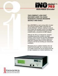
USERS RECORD Model <strong>720</strong> Serial No. ____________Date Purchased __________________Warranty Card Mailed? oPROGRAMMING AND OPERATIONINSTRUCTION MANUAL<strong>MODEL</strong> <strong>720</strong>R D SRADIO DATA SYSTEMRADIODATA ENCODERRev. 1February, 2008(Initial Release)1305 Fair Avenue Santa Cruz, CA 95060TEL: (831) 458-0552 FAX: (831) 458-0554Visit our Website: www.inovon.com
TABLE OF CONTENTSSection I - INTRODUCTION<strong>MODEL</strong> <strong>720</strong> PRODUCT DESCRIPTION ................................................................... 4The Radio Data System General Features<strong>MODEL</strong> <strong>720</strong> TECHNICAL SPECIFICATIONS ........................................................... 5BLOCK DIAGRAM ................................................................................................... 6UNPACKING AND INSPECTION ............................................................................. 6Section II - THE RADIO DATA SYSTEMTHE SYSTEM DEFINED .......................................................................................... 7RDS: EUROPE vs. AMERICA ................................................................................... 7RDS vs. RBDS or Whats in a Name?RDS APPLICATIONS SUPPORTED BY THE <strong>MODEL</strong> <strong>720</strong> ....................................... 8AF DI M/S PI PS PTY RAW RT TA TPCOMMUNICATING WITH THE <strong>MODEL</strong> <strong>720</strong> ENCODER ........................................ 10Section III - SOFTWARE INSTALLATION AND FIRMWARE SETUPINSTALLING THE SOFTWARE .............................................................................. 12Install Software First! Microsoft dot-NET FrameworkInstalling the USB DriverRUNNING THE SOFTWARE .................................................................................. 13Data EntryTHE MENU BAR .................................................................................................... 14RDS/RBDS Station Type: the M/S SwitchTxmtr Type: the DI Switch Header The Help MenuPI AND PTY CODES .............................................................................................. 16PI Code and the Calculator PTY Format IdentifierTHE PS FIELD - STATIC AND SCROLLING ........................................................... 17Static PS Scrolling-PS Parsing Safe ScrollingRADIO TEXT .......................................................................................................... 19DRTS Radio Text SpeedALTERNATIVE FREQUENCIES ............................................................................. 201
TRAFFIC ALERTS ..................................................................................................21TA TimeWRITING TO AND READING FROM THE ENCODER ............................................22ADDRESSING THE <strong>720</strong> WITH A SERIAL LINK .......................................................22Serial Connection Changing Baud RatesAuto-Detect Dual AddressabilityTHE SOFTWARE TERMINAL UTILITY ....................................................................23Updating Registers Using the Terminal UtilityUpdating the AF List Using Headers Saving to Non-Volatile MemoryAUTOMATION SYNTAX REQUIREMENTS .............................................................25No Header Operation One-Way Transmission Data EchoTHE FREE FORMAT GROUPS .............................................................................26ENCODER HOUSEKEEPING COMMANDS ...........................................................27Register Interrogation Encoder InitializationSaving to Non-Volatile Memory Encoder ResetFirmware Version Communication SpeedSection IV - ENCODER INSTALLATIONMOUNTING ............................................................................................................28Rack Requirements Heat DissipationAC (MAINS) POWER ..............................................................................................28Fuseholder Mains Voltage Selector Power CordRADIO FREQUENCY INTERFERENCE (RFI) .........................................................29Location Ground LoopsSELECTION OF OPERATING MODES ..................................................................29Sidechain Mode Loop-Through Mode JP3CONNECTING THE <strong>MODEL</strong> <strong>720</strong> ...........................................................................30Sidechain Mode (Preferred) Using a Separate Sync SourceLoop-Through Mode Composite STLManually Activation of the TA FlagDATA INTERCONNECTION ...................................................................................32Interconnect Cables Modem LinkCables Made In-HouseComputer or Terminal Requirements2
Section V - ENCODER OPERATIONTHE FRONT PANEL LCD DISPLAY ....................................................................... 34SETTING THE SUBCARRIER INJECTION LEVEL ................................................. 35Setting Subcarrier AmplitudeThe Built-In On-Screen RDS Level DisplaySubcarrier PhaseSection VI - CIRCUIT DESCRIPTIONSINTRODUCTION .................................................................................................... 37Component Annotation Stereo Pilot RecoveryRDS Waveform Synthesis Band-Pass FilterRDS Signal Combining and Output StageEncoder Data Formatting Power SupplySection VII - APPENDIXENCODER COMMANDS AND PROMPTS ............................................................. 40US AND EUROPEAN PTY LISTINGS ..................................................................... 41ALTERNATIVE FREQUENCY CHANNEL NUMBERS ............................................. 42COMPONENT PARTS LIST ................................................................................... 43PARTS SUPPLIERS ............................................................................................... 44SCHEMATIC DIAGRAMS ....................................................................................... 46INOVONICS WARRANTY ......................................................... (INSIDE BACK COVER)3
Section IINTRODUCTION<strong>MODEL</strong> <strong>720</strong> PRODUCT DESCRIPTIONThe RadioData SystemGeneralFeaturesThe Radio Data System allows the FM broadcaster to transmit certaindigital data along with his regular audio programming. Packetsof data transmitted on a low-level subcarrier identify the station andits particular broadcasting format, allow for transmission of songinformation, advertising and other text messages, and perform additionalID, control and housekeeping functions.<strong>Inovonics</strong> <strong>720</strong> is the companys third-generation full-function dynamicRadioData encoder capable of scrolling song titles and otherinformation on the RDS radio faceplate. All of the important staticIDs, traffic and other flags are of course supported, as well as specializedin-house applications.The front-panel LCD screen, built-in diagnostics and safeguards offeredfor the first time in the Model <strong>720</strong>, allow for near-foolproofRDS implementation at any FM radio station. Every step has beentaken to guarantee simple, straightforward and safe operation.Leading features of the <strong>Inovonics</strong> <strong>720</strong> include:• Front-panel LCD screen and built-in diagnostics, both in encoderfirmware and software.• Static data quickly programmed or updated with any Windows® PC using a serial or USB connection.• Works with popular hard-disk automation systems to transmitsong titles, contests, billboard updates, scrolling advertisements,etc.• A unique No Headers mode supports unformatted streamingtext feeds.• Scrolling messages are automatically parsed, or broken into8-character word groups for transmission, or can be scrolledone character at a time.• Loop-through or sidechain operation with any exciter/stereogenerator combination.• Operates with third-party hardware and software for increasedfunctionality.• Simple to install and easy to use; contains no trans-fats!4
<strong>MODEL</strong> <strong>720</strong> TECHNICAL SPECIFICATIONSStandards Supported:European CENELEC and UnitedStates NRSC.RDS Applications Supported:PI, PS, PTY, TP, TA, RT, AF, DI,M/S, RAW. (A detailed explanationof these applications begins onPage 8.)Operating Modes:Loop-Through:In loop-through operation, the RDSsubcarrier is internally mixed withthe MPX input and the combinedsignal is delivered to the RDS orMPX Output. The encoder hasunity gain in the loop-through modeand accepts a maximum level of 6volts peak-to-peak corresponding to±75kHz carrier deviation.Sidechain:In sidechain operation, only theRDS subcarrier appears at the RDSor MPX Output. The monitoredMPX (or TTL sync) is used solely tosynchronize the 57kHz RDS subcarrierwith the 19kHz stereo pilot.Pilot or MPX Input:An unbalanced, bridging (BNC) inputthat accepts either the composite/multiplex(MPX) signal or19kHz TTL-level pilot sync fromthe stereo generator. In the absenceof a 19kHz signal, the <strong>720</strong> revertsto an internal crystal timebase.RDS or MPX Output:An unbalanced, 75-ohm (BNC) outputto feed a wideband input of theFM exciter.RDS Injection Level:Subcarrier level is continuously adjustablefrom the front panel fromzero to 3V p-p. The LCD screengives both bargraph and voltagereadouts.Serial Data Port:A rear-panel RS-232 port (DB9) acceptsstatic encoder programmingand dynamic messaging from stationautomation. The <strong>720</strong> accommodatesall common data rates between1200 and 115,200 baud. <strong>720</strong>software features an automatic portand data rate ID utility to simplifyinitial connection and setup.USB Port:A front-panel USB port gives quickand easy access for encoder setup.All static messaging may be quicklyset with a laptop PC.TA Switching:The temporary TA flag is set eitherby a software command or with acontact closure through a rear-panelterminal strip. The <strong>720</strong> incorporatesa programmable TA-timeoututility to preclude TA flag violations.Supplied Software:Model <strong>720</strong> software runs on anyWindows® PC for either USB or serial(COM) port operation. Thesoftware is intuitive, self-guidingand contains numerous pop-up andother Help files.Power Requirements:105130VAC (0.250A Fuse) or210255VAC (0.125A Fuse),50/60Hz; 10W.Size and Shipping Weight:1¾H x 19W x 8D (1U); 7 lbs.5
BLOCK DIAGRAMFigure 1 is a simplified Block Diagram of the Model <strong>720</strong>. A full setof schematics may be found in the Appendix, Section VII, and accompanyingcircuit descriptions begin on Page 37.+5VRDS/MPXOUTPUTPILOT/MPXINPUTSIDELOOPBYPASSRELAY19kHzBPFRECT.LCD DISPLAYRDSLEVEL57kHzBPF(LOCK)PLLTIMEBASE(INJ.LEVEL)CPUPROCESSORSEEPROMDACRS-232SERIAL PORTUSBPORTTASWITCHFigure 1 Block Diagram, Model <strong>720</strong> RDS EncoderUNPACKING AND INSPECTIONAs soon as the equipment is received, inspect carefully for any shippingdamage. If damage is suspected, notify the carrier at once, andthen contact <strong>Inovonics</strong>.We recommend retaining the original shipping carton and packingmaterials, just in case return or transshipment becomes necessary.If returned for Warranty repair, shipping damage sustained as a resultof improper packing for return may invalidate the Warranty!IT IS IMPORTANT to complete and return the WarrantyRegistration Card that accompanies this manual, orthe Warranty registered on the Companys Website,www.inovon.com. This assures coverage of the equipmentunder terms of the Warranty, provides a means oftracing lost or stolen gear, and adds the user to a databaseto receive specific service instructions or software/firmwareupdates when issued. 6
Section IITHE RADIO DATA SYSTEMTHE SYSTEM DEFINEDRDS is a digital data channel transmitted as a low-level subcarrierabove the range of the composite stereo program signal in the FMbroadcast baseband. The data transmission (baud) rate is comparativelylow, yet it is quite robust because of redundancy and errorcorrection routines. The injection level of the 57kHz RDS subcarrieris a relatively low 3% to 4%, thus it does not rob the broadcaster ofsignificant program audio modulation.It is not within the scope of this Manual to cover the details of RDSsubcarrier coding and modulation. For this the reader is directed tothe Specification appropriate to his location, either the CENELECEN50067 Specification for Europe, or the United States NRSCSpecification. It is assumed that the user has some familiarity withthe concept of RDS since the balance of this Manual will deal withspecific implication of RDS implemented with the <strong>Inovonics</strong> Model<strong>720</strong> Encoder.In particular, the explanations of the various messaging and housekeepingfunctions afforded by RDS will help the reader become morefamiliar with what the system has to offer and how it can be used tothe broadcasters greatest advantage. These explanations begin onPage 8.RDS: EUROPE vs. AMERICAThe European Broadcasting Union (EBU) and its member countriesoriginated the concept of Radio Data transmission. The EuropeanRDS specification, CENELEC Standard EN50067, was first publishedin 1984, and was revised in 1986, 1990, 1991 and 1992.European RDS rapidly grew in use following initial adoption of theStandard. RDS is nearly universal throughout Europe; it is almostimpossible to find a European FM broadcasting station that does notcarry a RadioData subcarrier.The popularity of RDS in Europe is very much in contrast with initialreluctance on the part of US broadcasters to embrace this technology.This can be ascribed to material differences in broadcastingpractices.Almost without exception, FM broadcasting in the United States isdetached and independent; that is, each station originates its own 7
RDS vs. RBDSor Whats ina Name?programming. One exception might be Americas National PublicRadio, although for most of the broadcast day even NPR stationsoriginate, or at least schedule, their own programs.Much of European broadcasting is similar to the concept of networkradio that was common in the US prior to the 1950s. In Europe, acentral program originator may feed many transmitting facilities ofmodest power situated throughout the country. The European dispositiontoward lower-power transmitters can be found on the localradio level as well, with relay (re-broadcast) repeater transmittersat several different frequencies to blanket a designated service area.The European concept of a service area equates to the US broadcastersmarket. The subtle difference between these designationsfurther characterizes broadcasting practices and ethics. RDS benefitsthe European broadcaster through almost an altruistic endeavorto be of service to his listeners. The US broadcaster is marketing hisprogramming, and is primarily interested in how he can create additionalrevenue from RDS.As the Radio Data System was developed in Europe, it is understandablethat it is abbreviated RDS there. The first US implementationof RDS differed sufficiently from the European standard towarrant its being renamed the Radio Broadcast Data System, orRBDS to differentiate it from its European counterpart. Differencesbetween the two standards have been reconciled and minimized overthe years, yet RBDS prevails as the US designation. For the sake ofclarity and simplicity, the more generic and established term RDSwill be used throughout this Manual.RDS APPLICATIONS SUPPORTED BY THE <strong>MODEL</strong> <strong>720</strong>AFDIThe following is an alphabetical listing of RDS applications that arefully supported by the Model <strong>720</strong>. The standardized RDS applicationabbreviation is followed by an expansion of the applicationname and a short explanation of the function.List of Alternative Frequencies: A broadcasting network, or an individualbroadcaster using low-power rebroadcast transmitters(translators) to fill holes in his coverage area, can include a list ofall frequencies where the identical program can be heard simultaneously.Upscale RDS receivers constantly search for the best signalthat carries the very same program. When a stronger signal isfound, the radio re-tunes to it with no audible interruption. Theprincipal utility of this RDS function is with European radio networksand US stations with translators. The <strong>720</strong> can hold as manyas 25 Alternative Frequencies.Decoder Information: This is one of several flags that convey yes/noor other very basic data. This particular flag is meant to tell the receiverwhether the broadcast is monaural or is being transmitted inany of several methods of stereo or binaural broadcasting. This is arather esoteric and little-used function, and only monaural and con- 8
M/SPIPSPTYventional stereo transmissions are supported by the Model <strong>720</strong>.Music / Speech Switch: This flag simply indicates whether music orspeech is the primary broadcast programming. The purpose of thisfunction is not well explained in the respective Standards; hence itcomes as no surprise that it is not widely understood. In general,only all-news or talk-radio stations would fly the Speech flag.Program Identification: This block of data identifies the broadcaststation with a hexadecimal numerical code that represents the digitalsignature of the station. The receiver processes the PI code toassist automatic tuning features (station memories), and to preventfalse switching to alternative frequencies that might be shared bybroadcasters in nearby regions. The code is assigned by the broadcastingauthority in most countries, but in the US and in Canada itcan be calculated from a numerical encoding of station call letters.Model <strong>720</strong> software does this automatically as described on Page 16.Program Service Name: This is the stations street name thatmight typically appear on the receiver faceplate display. The PS canbe up to eight characters in length (including spaces) and can be assimple as the stations call letters (KWOW or KWOW FM) or a slogan(NEWSTALK or LIVE 95). The Program Service Name is automaticallydisplayed, even on automobile receivers, so it was meant to remainstatic.Because of driving safety considerations, broadcasters have, fromthe start, been discouraged from making the PS dynamic; that is,to send long messages in a succession of 8-character frames. As amatter of note, it remains a violation of both the CENELEC and theNRSC standards to flash or scroll the PS display. Nevertheless, thisnefarious practice of Scrolling-PS has become very common, bothin the US and abroad. The Model <strong>720</strong> has various modes for messagescrolling that offer a safe alternative to the static PS display.These are described beginning on Page 18.Program Type: The PTY data flag identifies the station format froma list of pre-assigned categories. Many RDS receivers are able toseek the listeners preferred format automatically. This means thata car radio can switch from a fading station to a stronger one thatcarries the same variety of music, although not the very same program.The PTY function of RDS helps a broadcaster catch a certaintransient audience share a long-distance truck driver for instance.Two distinct lists, one for RDS and the other for RBDS, remaina major disparity between the two systems. A listing of allPTY categories is given in the Appendix.Under some programming circumstances, the PTY identifier may bemade dynamic, changing between categories for a station thatdayparts (changes its format for specific time periods). The PTYcode is not meant to change from song to song or to accommodate atop-of-the-hour newscast, however. 9
RAWRaw Data Entry: The Model <strong>720</strong> provides a method of transmittingproprietary hidden data within legitimate RDS groups. This is aspecial use of the encoder for non-standard applications. Additionalnotes can be found on Page 26.RT Radio Text: This is a 64-character block of plain text that the listeneris able to select for visual display on only some radios. RadioText should not be confused with scrolling-PS, however, they aretwo separate and distinct messaging utilities that are available simultaneously.The Radio Text function is not often available on automobile receiversfor legacy safety considerations. This has precipitated thefrowned-upon practice of instead scrolling the PS field for song titlesand other dynamic messages. Radio Text has become relegated tothe display of more static information, such as the stations call-inphone number or Web address.TA Traffic Announcement: This is a temporary flag added to the RDSdata stream only as a traffic bulletin is being aired. Some RDS carradios can be set to search for traffic bulletins among various TPstations (see TP below) while tuned to a listeners preferred program,or even while playing a CD or MP3. As soon as any TP stationbroadcasts a traffic bulletin, the receiver temporarily switchesoverto receive it. When the bulletin is finished, the receiverswitches back to the original program, CD or MP3.TPThe takeover nature of the TA function has spawned numerousabuses, mostly in a misguided and evil attempt to steal listeners. Anaughty broadcaster might tease a listener he has just grabbed bymentioning some hot pop star interview thats up next on his stationas he goes into his traffic update. Or he might simply leave the TAflag on inadvertently (or not!). The Model <strong>720</strong> incorporates a TAcountdown timer that limits the traffic announcement to a userprogrammedmaximum number of seconds.Traffic Program Identification: The TP flag identifies the station asone that routinely broadcasts traffic bulletins for motorists as partof its normal, everyday programming. When the TP flag logo is displayedon the receiver faceplate, the radio is searching for trafficannouncements. The radio keeps track of TP stations offering thisservice to speed up the search-and-switchover process.COMMUNICATING WITH THE <strong>MODEL</strong> <strong>720</strong> ENCODERThe <strong>720</strong> may be addressed either by an RS-232 serial link orthrough the front-panel USB port. Either port may be used for initialsetup of the static flag and message registers, and Model <strong>720</strong>software serves both methods with an intuitive data-entry screenand self-guided help. This process is covered in Section III.Scrolling song titles require interconnection with station automation.Some RDS applications require continuous, on-line access to 10
the RDS encoder by outside service providers. The Model <strong>720</strong> offersthese capabilities so long as it can be directly addressed through itsserial port by simple ASCII commands from a computer or automationsystem.The Model <strong>720</strong> does not provide onboard TCP/IP network connectivityto enable online control via a Local Area Network or theInternet. <strong>Inovonics</strong> does offer RDS encoders that do provide a directnetwork connection. However, a third-party IP-to-serial converterfunctioning as a telnet server may be used with the <strong>720</strong> to offerTCP/IP connectivity.Early RDS deployment in Europe included a provision to link RDSencoders with one another for network support applications. TheUECP, or Universal Encoder Communication Protocol, was developedby CENELEC to support this form of operation. The <strong>720</strong> doesnot conform to the UECP. 11
Section IIISOFTWARE INSTALLATIONAND FIRMWARE SETUPNOTE: It is important to pre-program Model <strong>720</strong> firmware beforethe encoder is placed in the air chain. Firmware refers to the messageand flag registers that are non-volatile memory inside the unititself. Default register settings and messages are programmed-inat the factory as part of the final checkout process. Although benignin nature and intent, factory defaults could prove a source of confusionor embarrassment if allowed to air in lieu of settings and messagesappropriate to the installation.For this reason, Section III is presented ahead of instructions for installingand using the unit. We recommend tabletop familiarizationwith the <strong>720</strong> before bolting it into the rack.INSTALLING THE SOFTWAREInstallSoftwareFirst!Microsoftdot-NETFrameworkThe provided software runs on any Windows® computer runningMicrosofts Windows XP or later operating system. Software shouldbe installed on the computer before the computer is connected to the<strong>720</strong> Encoder. The same software is used for either USB or serialconnection between the computer and the Model <strong>720</strong>.<strong>720</strong> software utilizes components of Microsofts dot-NET framework.This utility has been distributed through routine MicrosoftXP updates and should be resident on any well-maintained PC. Ifsoftware installation pauses because dot-NET files are not found onthe computer, dot-NET has been supplied on the <strong>720</strong> software CD-ROM or may be download directly from the Microsoft Website.Insert the CD-ROM into the computers appropriate drive. The dischas an auto-run utility that will start the Windows Installer. Ifauto-run does not initiate the installation,open the file for theCD drive and double-click thesetup.exe icon.The image shown at the rightshould appear on your screen inshort order. This is the <strong>720</strong>Setup Wizard that will guide youthrough software installation.For a typical installation, simplycontinue to click Next> until theprogram has been completely in- 12
Installing theUSB Driverstalled, then click Close to exit the Setup Wizard.Software installation will place a shortcut on thecomputer Desktop. Do try to resist the overwhelmingtemptation to double-click the icon at this time. Wesincerely recommend first installing the USB driver,whether or not the encoders USB port will be yourprimary means of addressing the unit.At this time, power-up the Model <strong>720</strong> and connect it to the computerusing the USB cable provided.Windows® will post a message that new hardwarehas been found. Next, the Found NewHardware Wizard will start and guide youthrough the installation step.On the initial Welcome screen (below, left), check the box Installfrom a list or specific location (Advanced), and then click Next.Continue to click Next until installation reaches the window shownon the right. Highlight the driver on the CD-ROM drive named:C:\Program Files\<strong>Inovonics</strong> RDS Encoder <strong>720</strong>\USB Drivers as shown,and then click Next once again. When driver installation completes,the final screen will prompt you to clickFinish. At this point you will see anothernotification, this time advisingthat the new hardware is installed andready to use.RUNNING THE SOFTWARENOTE: Even if you have no intention of programming the encoderthrough the USB port in everyday operation, we recommend thatyou familiarize yourself with the static data entry procedure of encoderprogramming using the USB connection. If you have followedthis manuals sequence of encoder setup, the computer should beconnected to the USB port at this time. A procedure for establishingserial (COM) port communications between the computer and theencoder begins on Page 22. 13
With the computer and encoder USB ports connected, double-clickthe Model <strong>720</strong> Desktop icon. This should bring up the data-entrywindow shown below. Check first at the bottom of the window thatthe words USB Connected are displayed as indicated in the illustration.This verifies communication between the computer and theencoder.Data EntryThe following steps will show how data is entered into the variousRDS fields. As these fields are updated, all information is first heldby the software program on the computer, and then transferred tothe encoder with a WRITE button command.THE MENU BARClick File at the top of the window. Thisbrings down a sub-menu that allows theuser to save programming setups from theencoder to a small file on the computer, orto load setups from a file on the computer tothe encoder.Files will be assigned a .rds extension. The<strong>720</strong> file utility is useful for distributing a common encoder setupamong stations in a network, or for easily changing non-dynamicscrolling-PS or Radio Text messages without having to type them ineach time. .rds files may be kept in a folder created for them usingthe usual Windows® file-making rules and procedures.This menu tab also allows the user to reset the encoder to FactoryDefaults. Executing this command actually re-initializes the encoderwith factory settings, purging all setup options programmed by theuser from the non-volatile encoder memory. 14
The next menu item, Interface, shows at aglance whether the software and encoder areset to communicate via the front-panel USBport or the serial (COM) port. The USB boxwill be checked at this time. Clicking RS-232will bring up a port-assignment utility that isexplained on Page 22.Clicking Format opens anumber of programmingoptions, many of which arepertinent to the stationsRDS presence. Thesemust be set properly andwill be discussed individuallyhere.RDS/RBDS This is important! This selection essentially switches the Model <strong>720</strong>between North American and European operating modes, selectingthe proper PTY list and enabling the built-in PI calculator for USand Canadian call letters. Set this to RBDS in the US, Canada andMexico, and to RDS for the rest of the world.Station Type:the M/S SwitchTxmtr Type:the DI SwitchHeaderThis RDS flag is set to Music for the preponderance of todays FMbroadcasting. It would be set to Speech for an all-news or all-talkformat, even allowing for jingles and promo ditties.Set this to Stereo unless all transmissions are monaural. The <strong>720</strong>does not support the other, somewhat esoteric (and lost in history)DI options originally included in the CENELEC specification.An important feature of the <strong>720</strong>, and one that sets it apart from earliermodels and most competitive products, is the ability to transmitscrolling-PS messages from raw, unformatted ASCII text. In thepreferred mode of operation, scrolling-PS messages are preceded bythe special header DPS=. This prepares the encoder to format andsend the following text string to appear on the RDS radio faceplate.Satellite-delivery music services and some station automationequipment are able to output only raw, unformatted song title andartist information to accompany the audio programming. In theseinstances, sending the encoder properly-formatted data with the appropriateheaders would require either an additional computer routineor use of a third-party data consolidator to perform off-sitedata formatting.When the Format and Header selection is set to Yes (Normal Operation),the Model <strong>720</strong> responds only to scrolling-PS messaging that ispreceded by the required DPS= message header. When set to No(Satellite Streaming), all ASCII text received via the serial (COM)port will be parsed by the <strong>720</strong> and sent out as a scrolling-PS message.Needless to say, this software selection should be operated in the Yes(Normal Operation) mode except in those special installations thatutilize unformatted streaming text. This mode keeps the encoder 15
The Help Menuunder stable control by station automation and prevents automationsystem housekeeping commands from popping up on RDS radios.Once the encoder is set to the No (Satellite Streaming) mode and isreceiving streamed text, the <strong>720</strong> parses and shows everything thatcomes along. A special escape sequence is needed to get it out ofthis mode via the serial connection; this is explained on Page 26.The USB port may always be used to reset the encoder.The Help selection on the Menu Bar lets theuser turn on or off the Help balloons thatpop up for a short time when hovering-overvarious areas of the data-entry screen withthe mouse cursor. In About you can determinethe version of software thats beingused, and hyperlinks will take you to the <strong>Inovonics</strong> Website or facilitatethe composition of testy letters to our Tech Support department.A PDF of this manual loads when you click Manual.PI AND PTY CODESPI Code andthe CalculatorAs discussed on Page 9, the PI code identifies your station with aunique digital address. In many parts of the world this code is assignedby the national broadcasting authority or a regional standardsgroup.NOTE: A valid PI code is essential to proper RDS system operation.RDS radios may actually tune away from a station transmitting RDSdata groups that do not include a valid PI code.When the Model <strong>720</strong> is operated in the European RDS mode, the 4-character, hexadecimal PI code is typed directly into the PI box.Note that the box marked Call is grayed-out in the RDS mode. Inthe US and Canada, however, the PI code is derived from station callletters using a somewhat complex mathematical formula that gives acertain weighting to each letter in the stations call. The US andCanadian formulae are different, of course, and there is considerableroom for error when manually calculating the hex value from callletters. We have not included these formulae here, but interestedparties can refer to the appropriate Standard for a full and somewhatconfusing explanation of how the PI is actually calculated.Model <strong>720</strong> software contains a nifty built-in calculator that makesPI code entry entirely automatic in North America. When the encoderis in the RBDS mode, US or Canadian call letters may betyped directly in the Call box. As soon asvalid call letters are entered, the correspondinghex code will magically appear inthe PI box. US and Canadian calls mustbegin with K, W or C.NOTE: The <strong>720</strong> software calculator will not respond to call lettersassigned in countries other than the US and Canada. 16
PTY FormatIdentifierThe PTY (Program Type) code identifies the stations programmingformat from lists that have been compiled as part of the RadioDatastandards. There are two lists, one for the European RDS systemand one for the North American RBDS specification. The two listsare shown side-by-side in the Appendix.The appropriate PTY list is automatically loaded when the <strong>720</strong> is setfor the proper operating mode (RDS or RBDS) as explained previouslyin the Menu Bar discussion. With the proper encoder modeset, choose the station format from the drop-down list.Take care in choosing the PTY identifier as categories can be ambiguous.For instance, what if yours is a college station that relaysNPR programming? How about Rock and Top 40 crossovers? Justwhat can Cultural possibly pertain to in this less-gracious day andage? Would Serious Classics dare to include Stravinsky, Bartok orArthur Fiedler? For clarifications on these and other burning questions,refer to the appropriate RBDS or RDS Standard, or put yourquestion directly to the appropriate Standards Group. We regretthat the <strong>Inovonics</strong> Tech Dept. is not certified to fathom such conundrums.The PTY identifier can assume a semi-dynamic function in that it ispermitted to change from one format category to another if the stationdayparts, or alters formats during specific, extended segmentsof the broadcast day. The PTY should not change from song to songor to accommodate a 5-minute newscast.NOTE: The PTY codes relating to emergencies are reserved for trueemergency and emergency test situations only. Consult the appropriateStandards group before even thinking about airing these PTYcodes.THE PS FIELD - STATIC AND SCROLLINGStatic PSPS, or Program Service Name, was initially included in the RDSspecifications simply to display a fixed station identifier on the RDSradio faceplate. As of this writing, anything other than a static displayis still discouraged, although the scrolling of song titles andeven advertising messages has become universal practice on all continents.The <strong>720</strong> has two PS memory registers. One holds afixed, 8-character station-ID or station street name,and the second is a 128-character buffer register tohold a longer message for scrolling across the radiofaceplate. Clicking on the DPSS (Dynamic PS Speed)box will drop a menu. At this time, click 0-PS Only.This action will open the PS box so that an 8-character station ID may be entered. If Pop-Up Helpis turned on, then hovering over this area will display the helpfulhint of using uppercase text when entering this information. We 17
Scrolling-PSheartily recommend using all-caps for this short-form PS entry, aswell as for the scrolling-PS (DPS) field, and even for Radio Text.Some RDS radios are notable to display lowercasecharacters at all, or mayshow gibberish when lowercasecharacters are received.The Dynamic PS (DPS) register can hold up to 128 characters oftext, which can be made to scroll across the RDS radio faceplate in amanner and at a rate determined by software settings.An entry typed into the DPS field will be entered into non-volatileencoder memory once the WRITE button has sent it to the <strong>720</strong>. Thisallows programming the encoder at the studio and then relocating itto the transmitter site. Left undisturbed, the encoder will scroll thesame message endlessly.To enter text manually, it is first necessary to setthe DPSS box to a speed setting that opens theDPS field and sets it up for transmission. ClickDPSS and select a scrolling speed about midwaydown the list. The <strong>720</strong> can perform very rapidtransmission of the scrolling-PS message, butsome radios cannot keep up with a really fastscroll. We recommend a 6 as a top scrollingspeed.The field will now be open for data entry. Hovering over the DPSfield will pop up a Help balloon with hints and reminders. Placeyour cursor in the box, clear whats there, and type in your text.The character counter to the right of the field shows the number ofcharacters entered out of the 128-character maximum.ParsingIn online dynamic operation, the encoder is addressed by stationautomation through the serial (COM) port. Each data transfer of upto 128 characters will clear the contents of the DPS register and replaceit with the new song title or other information, which then repeatsuntil new data are received. What is manually typed into theregister at this time will be saved until new data is sent to the encoder,either by re-typing manually for a USB upload or by being replacedby data from the serial port.Parsing is the encoders smart mode of message transmission.Parsing breaks messages down into meaningful character groups forefficient display on the 8-character alphanumeric readout commonto all RDS receivers. Once the parsing options are set, the parsing 18
Safe Scrollingfunction is valid for any scrolling-PS message, whether it is manuallytyped and sent to the DPS register or received as ASCII textfrom station automation.Parsing sends short words together. THIS IS consists of seven charactersthat would be sent as a group; the same holds true for OF THEor NOW HERE. Longer words, up to and including 8 characters, aresent individually: WARNING or DOUGHNUT or BICYCLE.Words that exceed 8 characters are sidestepped at a slightly fasterrefresh rate through two or more consecutive displays. Examplesare EMERGENC followed by MERGENCY, or SUPERMAR followed byUPERMARK and PERMARKE and ERMARKET. This method of splittingwords gives a good sense of continuity and readability.The <strong>720</strong> affords three parsing options. These areselected with a drop-down menu in the Parse box.The method just described is the most popular andis selected by clicking 0-Auto in the box.The other two options select either Single, or what we call our safescrolling method explained below, or 8-character Block transmissionthat simply presents the incoming DPS text string as a succession of8-character blocks without the smart division into word groups.Hovering over this area brings up a Help balloon with this same information.We developed Safe Scrolling because of our concern over distractedautomobile drivers. When viewing a message composed of completewords or groups of words, a driver must pay close attention to theradio display or risk missing part of the message. Although themessage may be repeated over and over, the driver may tune in atthe end of a song, and in trying to find out who sang the numbermight run the risk of rear-ending another car.Safe Scrolling marches the message across the display screen onecharacter at a time, just like soldiers passing a reviewing stand. Anymessage would require a much longer transmission time in thismode, but a glance at the radio display every ten to fifteen secondsstill allows the driver to get the full message without missing anywords.RADIO TEXTRadio Text is a separate 64-character message that is transmitted tothe radio as a complete message; that is, it is not parsed by the <strong>720</strong>Encoder. The Radio Text message is held in buffer memory withinthe RDS receiver, and then scrolled or otherwise displayed in amanner determined by the receiver manufacturer.Some automobile receivers do not display Radio Text, others mayrequire the listener to press an INFO or TEXT button to see theRadio Text message. Radio Text is meant to be a static message,perhaps with station contact information or a general station promo 19
slogan. It may be entered manually and updated only when the informationchanges.Click into the Radio Text field, clear whats there and type in yourmessage. The character counter to the right of the field shows thenumber of characters entered out of the maximum of 64. Note thathovering over the field will bring up a Help balloon.DRTSRadio TextSpeedAlthough we extend our recommendation of using uppercase charactersfor this field, receivers with Radio Text capability are usuallyhigher-end radios that have a better chance of showing lowercasecharacters properly.Although Radio Text is sent to the receiver as a complete messageand not parsed by the encoder, the repetition rate at which the RadioText message group is refreshed is a user-defined variable.Once a station is tuned-in, the time interval before Radio Text is initiallydisplayed will depend on how frequently this RDS data groupis transmitted. Because Radio Text is a static message generallyrelegated to secondary information, the refresh rate does not needto be very high. On the DRTS (Dynamic Radio TextSpeed) scale of 1 to 9, a setting of 2 or 3 is usuallyquite adequate. Keep in mind that with a faster refreshrate Radio Text will monopolize transmissionresources and compromise the speed of scrolling-PSmessaging.The DRTS drop-down menu can also be set to zero.This turns Radio Text off completely and grays-outthe text entry field.ALTERNATIVE FREQUENCIESAs mentioned on Page 8, the <strong>720</strong> accommodates as many as 25 AlternativeFrequencies, the maximum number supported by theRDS/RBDS specification. These are other dial locations where thevery same program can be heard at the very same time (in sync!).The RDS radio hunts for the strongest signal thatcarries the program and seamlessly switches to it.This feature is used by European radio networks andby any independent station that have rebroadcasttranslators for extending coverage to areas wherethe main signal cannot be received well.Enter your Alternative frequencies by checking a box 20
for every dial location that carries the program. Always include themain transmitter frequency, otherwise the RDS radio will not switchback when required. A button below the Alternative Frequenciesbox allows all checks to be cleared at once.TRAFFIC ALERTSTA TimeThe TP / TA function is a useful provision of the RadioData System,but one with a potential for abuse. TP / TA is detailed on Page 10,including an explanation of how the utility can be abused and thesafeguards built into the Model <strong>720</strong> to prevent this.In order for a station to air TA (Traffic Alert) messages, it must firstbe listed as a TP (Traffic Program) station; that is, a station thatroutinely includes traffic updates in the normal programmingschedule. RDS radios keep track of TP stations and look for a TAflag only from among those stations.If your station does airroutine traffic announcements,check the TP box.This will then permit theencoder to send TA flagson demand.In keeping with RDS and RBDS regulations, the TA flag is to besent only for critical traffic-related announcements, and then onlyfor the actual duration of the accompanying voice message. We recommendusing only the direct-connected, hardware-switch-activationof the TA flag described on Page 32. However, as the encodermay be installed some distance from the studio and addressed by aserial (or modem) connection, provision has been made to set the TAflag with a software command.Nevertheless, the TA box on the <strong>720</strong> software screen may be checkedto initiate a TA flag. The flag is then transmitted immediately whenthe WRITE button is clicked. To clear the flag when the announcementis finished, uncheck the TA box and click WRITE once again.The <strong>720</strong> is equipped with a builtintimer that limits the maximumperiod for TA-flag transmission.This guards against a shortcircuitin a hardwired TA installation,or in the event that a second software command is not receivedat the end the TA announcement. TA may be set to time outafter a period of up to 255 seconds, with the 30-second factorydefaultvalue a typical setting. The TA timeout is set in the TATime box, and a Help balloon gives additional hints.Once the TA has timed-out, the TA function resets and has to be reinitiatedto proceed with another announcement. 21
WRITING TO AND READING FROM THE ENCODERWhen using the <strong>720</strong> software program to address the encoder from acomputer, once any single or series of RDS parameters have been setand any text entered, it is then necessary to click WRITE to send thedata to the encoder. The data will be transferred to non-volatilememory within the Model<strong>720</strong> at that time.Keep in mind that whenthe WRITE button isclicked, the entire contentsof the software screen willbe re-sent to the encoder.Similarly, clicking: READ will download the contents of the <strong>720</strong> Encodermemory back to the software where it can be read or saved asa .rds file.ADDRESSING THE <strong>720</strong> WITH A SERIAL LINKSerialConnectionChangingBaud RatesAuto-DetectThe following tutorial will give instructions on serial connectionwith the <strong>720</strong> encoder. The software detailed in the USB discussionis the same used for serial communication. As previously recommended,initial setup is easiest with a USB link.If currently connected, disconnect the USB cable from the encoder.Using the DB9 serial cable provided, connect the computer to theModel <strong>720</strong>.In the Menu Bar, click Interface and then RS-232. This will bring upa box labeled RS232 Settings. In this box the baud rate of the computerand encoder ports may be set manually using drop-downmenus, or a handy built-in utility will automatically determine settings.When changing the baud rate of the encoder, keep in mind that the<strong>720</strong> will not respond to an improper incoming baud rate. You willhave to know what baud rate the <strong>720</strong> is set to, establish communicationsat that rate, and then reset the computer baud rate if this isthe aim. The USB connection can always be used to reset the encodersbaud rate, or the built-in Auto-Detect utility can be used.Clicking Auto-Detect willstart a software utilitythat will interrogate allcomputer COM ports, determinewhich one is connectedto the <strong>720</strong> Encoder,and set the computersbaud rate to match the encoder. A valid connection will be confirmedby a notification at the bottom of the window, first showingFound, and then listing the port and its speed 22
DualAddressabilityAt this point COM port communication is established. Data entryusing the Windows® software may be done in exactly the samemanner as already has been described for the USB connection.With the <strong>720</strong> connected to station automation via the serial port, acomputer may still be plugged into the front-panel USB port to givesimultaneous, dual connectivity. This permits the easy editing ofstatic messages and flags without taking the encoder offline. The<strong>720</strong> will respond to whichever control source is currently sendingdata, whether this is a WRITE command from the Windows® softwareor individual register entries preceded by proper headers fromstation automation or a terminal, discussed next.THE SOFTWARE TERMINAL UTILITYWith a 2-way serial connection between the computer and encoder,first check that the encoder is set to the normal header mode. In theMenu Bar, click Format and hover over Header. See that Yes (NormalOperation) is checked. Next click Interface and then RS-232 toreopen the RS232 Settings box. Click Terminal to bring up the dataentrybox shown here. Hit the keyboard Enter key and the wordREADY will appear, confirming communication with the encoder.Next type??8 (two question marks followed by Enter). This willinterrogate the encoder and send back the contents of all ID, flagand message registers. An example of this interrogation is shown atthe top of the next page. The double question mark can be used atany time to make the encoder spill its guts. The exercise does notinterrupt or interfere with encoder operation. 23
UpdatingRegistersUsing theTerminal UtilityThe displayed syntax includes register designationheaders appropriate to each entry. Any single registermay be interrogated by typing its header and a singlequestion mark. For example, type SPEED?8 to requesta confirmation that the encoder port speed is indeed setto 9600 baud.In these programming instructions the exact ASCII syntax to be enteredon the keyboard will be given in the font used in the followingexample for the Radio Text field: TEXT=VISIT US AT THECOUNTY FAIR AND ON THE WEB AT www.wtop989.com8 . Specifically,the word TEXT followed by the equal sign and the messageto be sent, followed by the Enter key. The symbol8 denotes theEnter key.The illustration here shows thisRadio Text field entry. Note thatthe terminal utility does notword-wrap the text, but eachcharacter will be seen as it is entered.When the Enter key is pressed after the text has been typedin,the reply OK indicates that data has been received and saved inencoder RAM. Note that the answerback response is always a coupleof lines below the entry.The terminal utility is not intended for use as a text editor, in thattyping errors are not easily corrected in this window. If you make amistake, just press Enter and start over. Your mistake will be sentand saved in <strong>720</strong> memory, but if you update the error promptly itsdoubtful that anything untoward will be noticed. Thisillustrates the advisability of using the <strong>720</strong> software,rather than the terminal utility, for entering text.If improper syntax or an invalid entry is made, the encoderwill respond back with aNO. This is shown for anumber of improper entries here. The last entry wasan attempt to set the PI register by simply typing-incall letters. This wont work. The <strong>720</strong> PI calculator isin the software routine, which is not available when 24
Updating theAF ListUsing HeadersSaving to Non-Volatile Memorycommunicating directly with the encoder using the terminal utility.When a proper hex-value PI code is entered, however, the responseisOK.To keep the Model <strong>720</strong> backward-compatible with <strong>Inovonics</strong> earlierencoder models, the Alternative Frequency list (AF) may be enteredin either of two ways when using the terminal utility.1) Enter the frequency directly in MHz. Example: AF1=95.98 andAF2=97.18 . Up to 25 Alternative frequencies may be enteredin this manner. To clear the example second entry from the AFlist, for example, type AF2=08 . The <strong>720</strong> will resort the list, soAF slot numbers may change. Do a ??8 inquiry to view theupdated list.2) Enter the Alternative Frequency by direct entry of the channelnumber assignments listed in the RDS and RBDS Standards.Channel numbers are tabulated in the Appendix. An exampleentry would be AF1=1148 for 98.9MHz.All AF entries may be cleared by sending AF0=0 to the encoder.Messages and commands sent to the Model <strong>720</strong> as ASCII textstrings with headers are saved only in encoder RAM (Random AccessMemory). In the event of a power failure, this information willbe lost! In contrast, encoder programming using the Windows®software is automatically followed by a SAVE8 command thattransfers it to non-volatile encoder memory. This further emphasizesthe desirability of using <strong>720</strong> software for setting the variousRDS registers to protect their contents.Losing dynamic data should not be a worry, however, as the onlymessaging-with-headers generally streamed to the encoder is scrolling-PSsong titles or similar temporary data that is ordinarily updatedon a continuous basis. However, when using the terminalutility or other means of serially-addressing the encoder without the<strong>720</strong> software, following any command or message with SAVE8 willtransfer all data from the encoders RAM to non-volatile EEPROMmemory.AUTOMATION SYNTAX REQUIREMENTSGenerally, the Dynamic PS (DPS) field will be the only one addressedby station automation for sending song title and artist, stationpromo or similar information. In normal operation using headers,a typical automation command might be DPS=FLY ME TO THEMOON BY FRANK SINATRA8 . <strong>Inovonics</strong> has collaborated withmost of the automation system vendors to make sure that the <strong>720</strong>and other <strong>Inovonics</strong> encoders are compatible with all popular systems.The use of headers allows the encoder to ignore commands that arenot properly formatted. This way housekeeping or other miscellaneousdata streamed by the automation system will not appear onRDS radio displays. 25
No HeaderOperationOne-Way DataTransmissionData EchoWhen the <strong>720</strong> is configured for no header operation, everything inthe serial data stream that is sent to the encoder will be parsed andwill appear as a scrolling-PS message on RDS radios, contingentupon appropriate settings in the Parse and DPSS fields. This can betested by setting the <strong>720</strong> for this mode (clickFormat, then Header,and check No (Satellite Streaming). Once in this mode,bring up the terminal utility and type your text into the box. On anEnter command, the typed-in data will be sent, parsed and transmitted.To escape from the no header mode, press the keyboard Escape keythree times and then press Enter. The screen will show READY, indicatingthat it is back in the Yes (Normal Operation) mode.A return data path is not essential for encoder programming usingthe terminal utility or any other direct RS-232 data connection. TheModel <strong>720</strong> is able to accept programming commands on a strictlyreceive-only basis; this is useful, for example, if a studio-transmitterradio link (STL) includes only a one-way data path to the transmittersite. Keep in mind, however, that commands will not echo backa response. Using the supplied Windows® software always requiresa 2-way link.The <strong>720</strong> echoes incoming data. What comes up in the terminalutility window is actually coming back from the encoder. With onewaytransmission, text or commands typed into the terminal windowwill not be visible but will nevertheless be sent to the encoder.Again, use of the supplied software requires a 2-way link.THE FREE FORMAT GROUPSUnder the RDS and RBDS Standards, the RadioData system is ableto transmit unspecified data groups for in-house remote control, restrictedpaging or similar proprietary applications. These data canbe static, with the same information transmitted repeatedly, or controlledby an external application as a dynamic function.Certain free data groups are specified in the RDS and RBDS Standards.The Model <strong>720</strong> addresses these as a generic RAW datagroup consisting of three hexadecimal ASCII blocks (or packets) ofhexadecimal values; that is, three groups of four hexadecimal characters,which comes out to 3 x 16 bits. To enter data into thesegroups, send: RAW=bbbbccccdddd8 . The blocks represented bybbbb, cccc and dddd are the RDS/RBDS B, C and D data packets,which are described in the relevant Standard.Certain hexadecimal values in RDS/RBDS packets are already in usefor RDS functions supported by the <strong>720</strong> encoder. Group A, for instance,which precedes packets in the RAW group, contains the PIcode, which is programmed into encoder memory. But other groupscan be altered on a temporary basis without compromising functionsthat regularly depend on data in these groups. 26
An example of a user-developed command is RAW=4000170C65B0.This command would sneak data into the RDS stream indicatingthe current date and time, a function not otherwise supported by the<strong>720</strong> Encoder. The necessary checksums are automatically handledby the <strong>720</strong>. Consult the applicable RBDS or RDS Standard for moreinformation on using RAW data commands.ENCODER HOUSEKEEPING COMMANDSRegisterInterrogationEncoderInitializationSaving toNon-VolatileMemoryEncoder ResetFirmwareVersionCommunicationSpeedTyping: ??8 (two question marks followed by Enter) returns thestatus of all flag and ID settings and the contents of static messagebuffers to the screen. This was illustrated on Page 23. Registersmay also be interrogated individually using the same cited instructions.The initialize command is invoked by typing: INIT8 . This is anemergency recover command used to reestablish encoder operationin the unlikely event of an internal firmware crash. An INIT8command is not required to clear registers before updating encoderprogramming. Typing INIT8 erases all user programming that hasbeen saved in non-volatile memory and restores the encoder to factorydefaults.To save an existing encoder setup, use the READ button in the Windows®software to save an .rds file (see Page 22).RDS parameters are transferred from RAM to non-volatileEEPROM with a SAVE8 command. This is done automaticallywhen using the supplied Windows® software.Typing RESET8 performs a soft restart equivalent to powering theencoder down and back up again. This reset command does notclear the registers of programming commands that have been savedwith a SAVE8 command.Type REV8 for a display of the encoders firmware version. Thishas importance in determining whether differences exist betweenModel <strong>720</strong> encoders purchased at different times.The factory default for encoder speed is 9600 baud. To change thebaud rate to 2400, for example, typeSPEED=24008 . Acceptablebaud rates are 1200, 2400, 4800, 9600, 19200, 38400, 57600 and115200. The <strong>720</strong> may be addressed at the highest, 115200 baudspeed, but the trifling amount of data that is ever uploaded to theencoder really makes the highest speed a matter of supreme overkill.Even the default 9600 baud setting is lightning fast for encoderprogramming. Modest baud rates may prove far more dependable,especially with long data cable runs. The lowest baud-rate settingsare useful when the encoder is addressed using a dial-up modem ora slow data channel that is part of an STL radio link. 27
Section IVENCODER INSTALLATIONMOUNTINGRackRequirementHeat DissipationThe Model <strong>720</strong> mounts in a standard 19-inch equipment rack andrequires only 1¾ inches (1U) of vertical rack space. We recommendplastic or fiber washers to protect the painted finish around themounting holes.Consuming less power than an electric pencil sharpener, the <strong>720</strong> itselfgenerates negligible heat. The unit is specified for operationwithin an ambient temperature range extending from freezing to120°F/50°C. But because adjacent, less efficient equipment may radiatesubstantial heat, be sure that the equipment rack is adequatelyventilated to keep its internal temperature below the specifiedmaximum ambient.AC (MAINS) POWERFuseholderMains VoltageSelectorPower CordThe fuseholder is at the far left of the front panel. Apply downwardpressure and pull the cap outward to access the 5mm mains fuse.Note that the cap has space for a spare fuse as well. The cap is reseatedby reversing the removal process. This fuse also serves as afront-panel emergency power disconnect for the Model <strong>720</strong>.Unless specifically ordered for export shipment, the <strong>720</strong> is set at thefactory for operation from 115V, 50/60Hz AC mains. This can beconfirmed by checking the designation next to the mains connectoron the rear panel. The inappropriate voltage and fuse value willhave been crossed out at the factory with a black marker.To change the mains voltage, first remove the top cover of the unit.A clearly marked slide switch is right behind the AC mains connectoron the encoder circuit board. With power disconnected, use asmall screwdriver to set the switch for 115VAC or 230VAC operation.Be sure to install the appropriate fuse listed on the rear panel. Youcan remove the factory strikethrough with some, probably carcinogenicsolvent, and then cross out the inappropriate marking with anindelible felt pen.The detachable IEC-type power cord supplied with the encoder isfitted with a North-American-standard male plug. The individualcord conductors may be color-coded in either of two ways: 28
1) In accordance with US standards:BLACK = AC HOT WHITE = AC NEUTRALGREEN = EARTH GROUND2) To European CEE standards:BROWN = AC HOT BLUE = AC NEUTRALGRN/YEL = EARTH GROUNDRADIO FREQUENCY INTERFERENCE (RFI)LocationGround LoopsAlthough it is expected that the <strong>720</strong> to be installed alongside highpowertransmitters, please practice reasonable care and commonsense in locating the unit away from abnormally high RF fields.Because the unbalanced input and output of the Model <strong>720</strong> are chassis-ground-referenced,a mains frequency or RF ground loop couldbe formed between the input or output cable shield grounds and theAC power cord ground. A ground-lifting AC adapter may wellremedy such a situation, although the chassis must somehow be returnedto earth ground for safety. Generally, being screwed-down inthe equipment rack will satisfy the safety requirement.SELECTION OF OPERATING MODESSidechain ModeLoop-ThroughModeConfigured for sidechain operation, the rear-panel PILOT OR MPXINPUT connector simply bridges the output of the stereo generator,monitoring the composite/MPX signal to derive timing informationfrom the 19kHz stereo pilot. Alternatively, a TTL-level 19kHz syncsquarewave may be applied to this input. We do not recommendthis, however, because of possible phase ambiguities between thesynchronizing squarewave and the 19kHz pilot component in thecomposite, multiplex output of the stereo generator.In sidechain operation the encoders RDS OR MPX OUTPUT will containonly the RDS subcarrier; the composite/MPX signal is notrouted through the <strong>720</strong>. This operating mode will insure multiplexsignal integrity and assure uninterrupted program transmission inthe event of a catastrophic encoder failure (never happens!). As delivered,the <strong>720</strong> is configured for sidechain operation.Referring Figure 2, locate the 3-terminal jumper strip, situated justbehind the rear-panel RDS OR MPX OUTPUT connector on the circuitboard. The shorting shunt is positioned to the right forsidechain operation.With the Model <strong>720</strong> jumpered for loop-through operation (shortingshunt to the left), the RDS subcarrier is internally combined withthe composite/MPX signal and the RDS OR MPX OUTPUT will includethe composite/MPX program signal at unity gain. The <strong>720</strong>provides a relay bypass of the composite/MPX signal in the event ofpower loss. 29
R7K1SidechainMode(RDS ONLY)R8LOOP/SIDEIC4JP1MPX/RDSOUTPUTFigure 2 Encoder Mode JumperingLoop-ThroughMode(MPX ON)JP3JP3 is included to facilitate any future firmware updates. Instructionsfor this procedure will accompany any updates issued. Headerconnector J5 is used only for initial factory programming of the <strong>720</strong>.CONNECTING THE <strong>MODEL</strong> <strong>720</strong>Sidechain Mode(Preferred)Using a SeparateSync SourceIMPORTANT: The <strong>720</strong> encoder must be properly configured forthe desired operating mode: sidechain or loop-through. ConsultFigure 2 to confirm that the encoder circuit board is properlyjumpered before connecting the Model <strong>720</strong> to other air-chain equipment.ALSO: Be sure that encoder firmware has been programmed accordingto the instructions in Section III.Using a BNC T adapter at the composite/MPX output of the stereogenerator, connect one side of the T directly to a wideband (composite/MPX)input of the FM exciter and the other side to the PILOTOR MPX INPUT of the Model <strong>720</strong> as shown in Figure 3. This is onlya bridging sync connection with the circuit board jumpered forsidechain operation and does not affect the composite/MPX signal.If the stereo generator has a dedicated 19kHz RDS sync output, youmay connect this to the encoder PILOT OR MPX INPUT for sidechainoperation. We do not recommend this, however, as this output maynot have an accurate phase relationship with the stereo pilot in thecomposite/MPX output signal.Cable the RDS OR MPX OUTPUT of the encoder to a second wideband(subcarrier) input of the FM exciter. 30
FM STEREO GENERATORPROGRAMLINE INMPX OUT<strong>MODEL</strong> <strong>720</strong> ENCODERPILOT OR RDS OR MPX RS-232 LOCALMPX INPUT OUTPUT COM PORT TA CONTROLFM EXCITERRF OUTPUT1 2 3 WIDEBAND INPUTS Figure 3 Sidechain Encoder ConnectionLoop-ThroughModeIn the loop-through mode, the output of the stereo generator is cableddirectly to the PILOT OR MPX INPUT of the Model <strong>720</strong> as shownin Figure 4. Connect the RDS OR MPX OUTPUT of the encoder to acomposite/MPX wideband input of the FM exciter. When internallyjumpered for loop-through operation, the composite/MPX signalpasses through the encoder with unity gain with the RDS subcarrieradded, or routed directly through the encoder by the bypass relay inthe event of encoder power loss.FM STEREO GENERATORPROGRAMLINE INMPX OUT<strong>MODEL</strong> <strong>720</strong> ENCODERPILOT OR RDS OR MPX RS-232 LOCALMPX INPUT OUTPUT COM PORT TA CONTROLFM EXCITERRF OUTPUT1 2 3 WIDEBAND INPUTS Figure 4 Loop-Through Encoder Connection 31
Composite STLManualActivationof the TA FlagIf a composite STL is used between the studio and the transmittersite, the <strong>720</strong> encoder may be kept at the studio for direct connectionwith station automation. Figures 3 and 4 still apply, with the STLtransmitter taking the place of the FM exciter.The Traffic Announcement feature is a temporary command. Thisflag must coincide with the actual voice warning of a notable trafficcondition. The encoder includes a provision to access this flag witha manual switch closure, which will doubtless prove faster, moreconvenient and more reliable than software control of the TA function.A cable may be taken from the LOCAL TA CONTROL terminal stripon the rear panel of the encoder to a normally open momentary(spring-return!) pushbutton switch located conveniently at the announcersoperating position. The screw-terminal part of this connectorunplugs from the rear panel to make connection easier. Atwisted pair is acceptable for a short run, but anything more thanabout 20 feet should probably be a shielded (coax) cable; shieldgrounded, of course.The TA flag will be transmitted for as long as the switch is helddown. It is important that this alert is active only for the duration ofa traffic announcement. The TA flag should be turned off immediatelyafter completing the verbal traffic warning, which should beautomatic if a spring-return switch is used.The <strong>720</strong> does incorporate a down-counting TA timer to prevent acontinuous switch closure from signaling a permanent TA flag. Thistimer is user-programmed for a specified time in seconds, afterwhich the TA flag is automatically turned off until the switch isopened and then closed again. Programming of this timer is coveredon page 21.DATA INTERCONNECTIONInterconnectCablesFor dynamic operation of the <strong>720</strong>, the rear-panel RS-232 SERIALDATA INTERCONNECT port is addressed in simple ASCII text. Theprimary utility of this port is to connect with station automation foruploading scrolling-PS and Radio Text messages. Communicationsyntax for direct connection with automation is explained beginningon Page 24 and in the Appendix.The various RDS flags and other static data should already havebeen programmed per the instructions in Section III.When the <strong>720</strong> is connected to a computer for static programming,the front-panel USB port is by far the most convenient means, and asuitable cable has been included with the encoder. Serial-port connectionwith station automation for dynamic messaging requires astraight-through, pin-for-pin DB9 extension cable, and a short onecomes with the <strong>720</strong>. Serial cable pinout is diagrammed in Figure5A. 32
Modem LinkA modem link also may be used for addressing the encoder from aremote location. When properly configured, a modem link will appeartransparent, as if the encoder were connected directly to thecontrolling computer or automation system. Figure 5B showsproper pin connections for the cable used to connect the Model <strong>720</strong>to a conventional external modem. The three conductors shown arethe only ones actually required in this case.1 2 3 4 56 7 8 9(GND)DB9 Female(COMPUTER orAUTOMATIONend)DB9 Male(ENCODER end)2 3 72 3 5(GND)DB25 Male(MODEM end)DB9 Male(ENCODER end)Figure 5A Figure 5BComputer or Automation Cable Modem CableCables MadeIn-HouseComputer orTerminalRequirementsOccasionally there is a need to makea data cable in-house; to connect theEncoder to the data output of an STLreceiver, for instance. Figure 5C illustratesthat only three connectionsare actually required for the encodersRS-232 interface. A cable likethe one depicted can be made easilyand will work just as well as a serialextension cord with all nine conductorsconnected.1 2 3 4 56 7 8 9(GND)DB9 Female(STL RECEIVERend)DB9 Male(ENCODER end)Figure 5CHousemade CableAlthough the supplied Windows ® software and front-panel USB portafford the easiest method of entering static RDS data, the encodermay also be addressed serially using the terminal-emulation programthat is part of the <strong>720</strong> software package (see Page 23). A simpledumb RS-232 terminal and, of course, station automation mayalso address the encoder directly. The encoder can accommodatemultiple baud rates, but the factory default is 9600 baud. Set terminalor automation for: 9600-baud / 8 data bits / no parity / onestop bit (9600,8,N,1). 33
Section VENCODER OPERATIONTHE FRONT PANEL LCD DISPLAYThe <strong>Inovonics</strong> <strong>720</strong> Encoder is nominally menu driven, which inthis case simply means that contents of internal data registers, plusdata-on-the-fly and a readout of the subcarrier voltage level, may beviewed on the front-panel LCD display using the s (up) andt(down) buttons to cycle through a number of different screens. Itis comforting to know that no changes to the data registers can bemade with these front-panel buttons; the USB and serial ports arethe only means of updating the data to be transmitted.The following listing explains the contents of each LCD screen.SCREENNUMBER 34 WHAT IS DISPLAYEDThis is the STATUS: screen. It shows whether the encoder islocked to the stereo pilot or is running from the internal crystal01 timebase. SENDING PS> < displays what is actually beingseen on the listeners radio faceplate. When a TA flag issent, TA FLAG ON is also displayed in this area as aflashing alarm.DATA: shows incoming commands on the fly. This is usefulfor verifying communications between the computer or automationand the encoder, and to read the commands to check02 that they are valid. When incoming commands are sent usingthe supplied software, the contents of all registers are updatedwhether or not changes have been made. Incoming programmingwill include spaces and carriage returns, or 8symbols, necessary parts of the text strings.03 DPS= displays the contents of the scrolling-PS buffer.PARSE: indicates the parsing mode, along with a legend describingwhichDPS Method is programmed.04PS: displays the short form Program Service name programmedinto <strong>720</strong> memory and whether its transmission is en-05abled or disabled per the DPSS setting.DPSS: shows the scrolling-PS speed setting, along with a legenddescribing the options.0607 TEXT: displays the contents of the Radio Text buffer.DRTS: shows the Radio Text refresh rate, along with a descriptivelegend.08PI: indicates the hex value of the stations PI code. For North09 American RBDS operation, the stations CALL LETTERS: willalso be displayed here.PTY: displays the code number of the stations Program Type,10 or format, along with a matching (DESCRIPTION) from theappropriate RDS or RBDS list.11 MS: the setting of the Music/Speech switch, with legend.12 DI: Decoder Information, mono or stereo transmissions.
TP: whether or not the station carries traffic information programmingas part of its broadcast schedule.13TA: shows whether the Traffic Alert is ON or OFF; this is also14indicated on the 01 STATUS: screen. DisplaysTA:N/A whenTP is off (TP:0).TATIME: indicates the number of seconds programmed for the15automatic TA timeout function.HEADER: shows whether the <strong>720</strong> is set for the normal header16mode for scrolling-PS, or set to accept unformatted text.17 SPEED: the setting of the encoders RS-232 baud rate.AF1: Screen 18 and successive screens show any AlternativeFrequencies (orNONE) programmed into the <strong>720</strong> encoder.The bottom LCD screen indicates RDS LEVEL:, the actualpeak-to-peak voltage of the RDS subcarrier at the output of theModel <strong>720</strong>. A bargraph representation is also shown.18(and up)(FinalScreen)SETTING THE SUBCARRIER INJECTION LEVELSettingSubcarrierAmplitudeThe front-panel INJECTION LEVEL ADJUST potentiometer sets thelevel of the RDS subcarrier. This is a 15-turn potentiometer to yieldthe required adjustment resolution. The <strong>720</strong> design has included ameasurement utility to display the peak-to-peak amplitude of theRDS subcarrier on the LCD screen. By scrolling down the LCDmenu to the very last screen, the peak-to-peak amplitude of the subcarrieris displayed directly in peak-to-peak volts.In the sidechain mode of operation, the RDS subcarrier is the onlysignal that appears at the rear-panel RDS OR MPX OUTPUT connector.Because some exciters require a high signal level at auxiliarywideband (SCA) inputs, the RDS signal has been made adjustable toany value between zero and 3 volts, peak-to-peak.In loop-through operation of the encoder, the composite/MPX programsignal that is fed to the PILOT OR MPX INPUT appears withunity gain at the RDS OR MPX OUTPUT. The level of the composite/MPXprogram signal will typically be in the 3- to 5-volt p-p range.The same 0-3V RDS subcarrier level capability of the <strong>720</strong> is availablein the loop-through mode as well, so obviously the INJECTIONLEVEL ADJUST control will be closer to the counterclockwise end ofits travel to give a level in the 0.16 volt p-p range corresponding tothe typical 3% to 4% RDS injection.Injection level is best set with a modulation monitor that includes asubcarrier measurement utility. Alternatively, a basic mod-monitorcan be used alone, but program modulation and the stereo pilotmust be turned off to resolve the low RDS injection level.NOTE: If using a mod-monitor without a separate subcarrier measurementcapability, keep in mind that mod-monitors are peakrespondingfor total modulation readings near 100%, but may be average-respondingfor low-level measurements. Because the RDSsubcarrier is a complex waveform, an average reading of 3% RDS injectioncan represent a level that is substantially higher when measuredpeak-to-peak. The peak level is of concern in broadcasting. 35
The Built-InOn-ScreenRDS LevelDisplaySubcarrier PhaseIf the peak-to-peak level of the composite/MPX for 100% carrier deviationis known, the RDS level may be set with reasonable accuracyusing the built-in subcarrier measurement utility of the <strong>720</strong>. Thecomposite/MPX is easily measured by bridging the input of the exciterwith an oscilloscope using a BNC T adapter. Monitoringnormal program material that has passed through a typical audioprocessor, the 100%-modulation value will be apparent on thescope. Take this figure and multiply it by 3 to 4 percent, and thenset the front-panel INJECTION LEVEL ADJUST control to the calculatedvalue. For example, if the composite/MPX level is 4V p-p at100% modulation, set the RDS level to 4 X .035, or 0.14V p-p for3.5% injection.In the United States, the FCC permits an extra 5% modulation foreach added FM subcarrier, with total modulation not to exceed 110%with two or more subcarriers. Consult current local regulations regardingthis matter.According to the RDS and RDBS Specifications, the 57kHz RDSsubcarrier may be either in phase or in quadrature with the 19kHzstereo pilot. Both phase relationships are shown in Figures 6 and 7,respectively. Note that the quadrature relationship in Figure 7yields a slightly lower peak level, which suggests the possibility ofmarginally greater carrier modulation by the program audio signal.Figure 6 Subcarrier In PhaseFigure 7 Subcarrier In QuadratureThe Model <strong>720</strong> is skillfully and meticulously aligned at the factory toensure that the subcarrier is in phase with the stereo pilot, whetherthe encoder is used in the sidechain or in the loop-through operatingmode. Although some stereo generators are equipped to supply a pilot-syncreference for RDS (usually a TTL-level squarewave), thisreference may or may not be in exact phase with the actual stereo pilotcomponent in the composite/MPX signal. For this reason we recommendusing the composite/MPX signal for synchronization. Inthe sidechain mode, the Model <strong>720</strong> simply bridges the output of thestereo generator and does not load or otherwise compromise thecomposite/MPX signal. 36
Section VICIRCUIT DESCRIPTIONSINTRODUCTIONComponentAnnotationStereo PilotRecoveryRDS WaveformSynthesisThis Section details the circuitry of the <strong>Inovonics</strong> Model <strong>720</strong>RDS/RBDS RadioData Encoder. Circuit descriptions refer to thetwo pages of Schematic Diagrams contained in the Appendix, SectionVII.Schematics for the <strong>720</strong> may appear to have component referencedesignations assigned in a somewhat haphazard manner, but this isnot really the case at all. Rather than annotate the schematic in alogical sequence, we have instead elected to designate the actualcomponents on the main circuit board in a top-to-bottom and left-torightmanner, following the physical placement of the parts. It isour expectation that this will simplify any necessary troubleshooting,as the physical component can be located quickly followinganalysis of the schematic.A sample of the composite/MPX signal is filtered by the biquadband-pass configuration of op-amps IC8B, IC9A and IC9B to recoverthe 19kHz stereo pilot. Trimmer adjustment R49 is used to finetunethe phase of the recovered pilot signal. PLL IC10 lends furtherfiltering action and squares-up the 19kHz waveform, as well as providinglogic to indicate pilot lock.IC11 is a second PLL that includes frequency-divider IC12 in itsloop. The output of IC11 is a 114kHz squarewave, a six-times multiplicationof the stereo pilot. This is a clocking frequency at twicethe RDS subcarrier rate that is used by digital processing stages togenerate the RDS subcarrier.IC7 is a PIC, a simple form of microprocessor with onboard memory.The function of this data processing block is to synthesize thedouble-sideband, suppressed-carrier RDS waveform. The PIC hasan on-board crystal oscillator to establish an internal master clockthat is an exact multiple of the RDS subcarrier. Thus IC7 is able tofree-run with sufficient precision to generate the subcarrier if lockwith the stereo pilot is not obtained.Subcarrier waveforms are sent as parallel data to the resistor laddercomprising resistors R25 through R40. This ladder performsthe D/A conversion for digital synthesis of the RDS subcarrier. 37
Band-PassFilterRDS SignalCombining andOutput StageEncoder DataFormattingPower SupplyThe segmented RDS waveform from the D/A resistor ladder ispassed through dual band-pass filter stages, IC6B and IC6A. This57kHz filter removes higher-order distortion components inherentto the digital-synthesis process.R3 is the front-panel INJECTION LEVEL ADJUST control that determinesthe magnitude of the RDS subcarrier at the encoder output.The adjusted level is rectified by IC5A and IC5B. Peak-weightedDC from this rectifier becomes the basis for front-panel digital readoutofRDS LEVEL: in volts on the LCD display.IC4A is the encoder output driver stage. With JP1 jumpered asshown for SIDE (sidechain) mode, only the level-adjusted RDS subcarrierwill be passed at unity gain to the rear-panel connector.With JP1 jumpered for LOOP (loop through) operation, the composite/MPXsignal applied to the rear-panel PILOT OR MPX INPUT connectoris passed through this stage at unity gain and will appearcombined with the RDS subcarrier at the output. Relay K1 providesa failsafe bypass path for the composite/MPX signal in the loopthroughoperating mode if encoder power is lost.IC13 is a second PIC microprocessor that is responsible for receivingand formatting all incoming RDS data. IC13 is able to interfacedirectly with the encoders USB port, and RS-232 interface chip IC3performs level conversion for the 2-way serial data (COM) port.IC13 also addresses the front-panel LCD display and receivesup/down menu commands from the panel buttons. The hardwireTA command is also processed by this PIC. IC13 is interconnectedwith the RDS waveform generator, IC7, and provision has been includedfor updating the firmware in IC13 through the encodersUSB port.IC1 and IC2 are linear voltage-regulator ICs that supply ±5VDC toencoder circuitry. The power transformer has dual primary windingsfor operation from 115V and 230V AC mains. 38
Section VIIAPPENDIXThis section of the Model <strong>720</strong> Manual containsCertain Tabulated Items, Parts Listings,Schematic Diagrams and an explanation of<strong>Inovonics</strong> Most Generous Warranty Policy. 39
ENCODER COMMANDS AND PROMPTSPARAMETER COMMAND DATA ENTRYProgram Identification PI= 4 digit HEX number (station digital address)Program Service Name PS= 8 (max) ASCII characters (station street name)Dynamic PS DPS=128 (max) ASCII characters (for scrolling messagesin the PS field)Dynamic PS Speed DPSS= (0 = OFF, 1 = slow (to) 9 = fastest)Dynamic PS MethodPARSE= 40 (0 = Auto-Parse, 1 = Single (SafeScrolling) 8 = BlockProgram Type PTY= 1 or 2 digit number to describe station format.Traffic Program TP= (0 = no, 1 = yes)Traffic Alert TA= (0 = flag off, 1 = flag on)Software TA Timeout TATIME= (1 to 255 seconds to timeout)Alternative FrequenciesAF1=(0 = NONE; 1 to 204 = channel in100kHz increments, 87.6MHz to 107.9MHz); Frequencyin MHz may also be entered directly.Decoder Information DI= (0 = Mono, 1 = Stereo)M/S MS= (0 = Speech-Only, 1 = Music)Radio Text TEXT= 64 (max) ASCII charactersDynamic Radio Text Speed DRTS= (0 = Radio Text off; 1 = slow (to) 9 = fastRS-232 Serial Baud RateRESPONSEOKNOSPEED=COMMAND?1200, 2400, 4800, 9600,19200, 38400, 57600, 115200SPECIAL COMMANDSFollowing a header returns status of encodermemory for that specific parameter; eg.: DI?.?? Returns all data in encoder memory.REVSAVERESETINITReturns firmware revision number.Saves encoder RAM to non-volatile EEPROM.Resets the encoder as if AC powerwere cycled off and back on.Initializes the encoder to all factory defaults.MEANINGThe command is properly formatted and hasbeen received and executed by the encoder.Incoming data is not properly formattedand has not been executed by the encoder(NONE) Data sent is ignored by the Model <strong>720</strong>.
US AND EUROPEAN PTY LISTINGSPTY US (NRSC) RBDS EUROPE (CENELEC) RDS0 None None1 News News2 Information Current Affairs3 Sports Information4 Talk Sports5 Rock Music Education6 Classic Rock Music Drama7 Adult Hit Music Culture8 Soft Rock Music Science9 Top 40 Music Varied10 Country Music Pop Music11 Oldies Music Rock Music12 Soft Music Easy Listening Music13 Nostalgia Music Light Classics Music14 Jazz Serious Classics Music15 Classical Music Other Music16 Rhythm and Blues Music Weather17 Soft R and B Music Finance18 Foreign Language Childrens Programs19 Religious Music Social Affairs20 Religious Talk Religion21 Personality Phone-In22 Public Non-Commercial Travel23 College Leisure24 (unassigned) Jazz Music25 (unassigned) Country Music26 (unassigned) National Music27 (unassigned) Oldies Music28 (unassigned) Folk Music29 Weather Documentary30 Emergency Test Alarm Test31 Emergency! Alarm! 41
ALTERNATIVE FREQUENCY CHANNEL NUMBERSMHz CHAN MHz CHAN MHz CHAN MHz CHAN87.6 1 92.7 52 97.8 103 102.9 15487.7 2 92.8 53 97.9 104 103.0 15587.8 3 93.9 54 98.0 105 103.1 15687.9 4 93.0 55 98.1 106 103.2 15788.0 5 93.1 56 98.2 107 103.3 15888.1 6 93.2 57 98.3 108 103.4 15988.2 7 93.3 58 98.4 109 103.5 16088.3 8 93.4 59 98.5 110 103.6 16188.4 9 93.5 60 98.6 111 103.7 16288.5 10 93.6 61 98.7 112 103.8 16388.6 11 93.7 62 98.8 113 103.9 16488.7 12 93.8 63 98.9 114 104.0 16588.8 13 93.9 64 99.0 115 104.1 16688.9 14 94.0 65 99.1 116 104.2 16789.0 15 94.1 66 99.2 117 104.3 16889.1 16 94.2 67 99.3 118 104.4 16989.2 17 94.3 68 99.4 119 104.5 17089.3 18 94.4 69 99.5 120 104.6 17189.4 19 94.5 70 99.6 121 104.7 17289.5 20 94.6 71 99.7 122 104.8 17389.6 21 94.7 72 99.8 123 104.9 17489.7 22 94.8 73 99.9 124 105.0 17589.8 23 94.9 74 100.0 125 105.1 17689.9 24 95.0 75 100.1 126 105.2 17790.0 25 95.1 76 100.2 127 105.3 17890.1 26 95.2 77 100.3 128 105.4 17990.2 27 95.3 78 100.4 129 105.5 18090.3 28 95.4 79 100.5 130 105.6 18190.4 29 95.5 80 100.6 131 105.7 18290.5 30 95.6 81 100.7 132 105.8 18390.6 31 95.7 82 100.8 133 105.9 18490.7 32 95.8 83 100.9 134 106.0 18590.8 33 95.9 84 101.0 135 106.1 18690.9 34 96.0 85 101.1 136 106.2 18791.0 35 96.1 86 101.2 137 106.3 18891.1 36 96.2 87 101.3 138 106.4 18991.2 37 96.3 88 101.4 139 106.5 19091.3 38 96.4 89 101.5 140 106.6 19191.4 39 96.5 90 101.6 141 106.7 19291.5 40 96.6 91 101.7 142 106.8 19391.6 41 96.7 92 101.8 143 106.9 19491.7 42 96.8 93 101.9 144 107.0 19591.8 43 96.9 94 102.0 145 107.1 19691.9 44 97.0 95 102.1 146 107.2 19792.0 45 97.1 96 102.2 147 107.3 19892.1 46 97.2 97 102.3 148 107.4 19992.2 47 97.3 98 102.4 149 107.5 20092.3 48 97.4 99 102.5 150 107.6 20192.4 49 97.5 100 102.6 151 107.7 20292.5 50 97.6 101 102.7 152 107.8 20392.6 51 97.7 102 102.8 153 107.9 204 42
COMPONENT PARTS LISTNOTE: The majority of components used in the <strong>Inovonics</strong> <strong>720</strong>RDS/RBDS RadioData Encoder are surface-mounted parts, whichare very difficult to remove and replace in the field. We thereforerecommend returning the unit to the factory should repair becomenecessary.Not all components with schematic reference designations may beindividually listed, and component descriptions may or may notspecify a particular manufacturer or vendor. When no manufactureris called out, the term (open) advises that any manufacturers productcarrying the given part number (or the same description in thecase of a generic part) is acceptable.Should you need to order a part that is not listed here, call, write,fax or e-mail the factory with a brief description of what it is thatyou need. Well then do our very best to figure out what to sendyou maybe a nice surprise!C1,2 Capacitor, Y-class Ceramic Disc, .0047µF, 440VAC; Murata/ErieDE7150 F 472M VA1-KCC3,4 Capacitor, Electrolytic, radial leads, 2200µF, 35V snap-in;Digi-Key P7 466-NDC5-13,15,16,23-25,29, Capacitor, Monolithic Ceramic, 0.1 µF, 50V,30,32,33,38,42,43 SMD 0603; (open)C14,31,37 Capacitor, Monolithic Ceramic, 2.2µF, 25V,SMD 0805; (open)C17,18,19,20,36 Capacitor, Monolithic Ceramic, 0.001µF, 50VSMD 0603; (open)C21,22,39,40 Capacitor, Monolithic Ceramic, 22pF, 50VSMD 0603; (open)C26 Capacitor, Monolithic Ceramic, 0.01µF, 50VSMD 0603; (open)C27, 28 Capacitor, Polypropolyne, 0.0022 µF, 50V;Wima FKP2 seriesC34 Capacitor, Monolithic Ceramic, 0.0033µF, 50VSMD 0603; (open)C41 Capacitor, Monolithic Ceramic, 0.47µF, 50VSMD 0603 (open)CR1 Diode, Bridge Rectifier; Digi-Key DF005SDI-NDCR2,3 Diode, Silicon Signal, SOD-123; (open) 1N4148WF601 Fuseholder; Littlefuse 0286067 (The fuse itself is a5mm X 20mm normal fast blow type; value tomatch the specification stated on the rear panel.)IC1 Integrated Cct., DPAK-3; (open) 78M05IC2 Integrated Cct., DPAK-3; (open) 79M05IC3 Integrated Cct., DIP; (open) MAX232N 43
IC4,5 Integrated Cct., 8SOIC; (open) OP279IC6,8,9 Integrated Cct., 8SOIC; (open) LF353IC7,13 Integrated Cct.; Microchip 18F4550 PIC (Requires factoryprogramming, available only from <strong>Inovonics</strong>)IC10 Integrated Cct., 8SOIC; (open) LM567CMIC11 Integrated Cct., 16SOIC; (open) CD4046BTDIC12 Integrated Cct., 16SOP; (open) CD4018BNSRJ1 Connector, AC Mains; Switchcraft EAC303J2 Connector, USB; Digi-Key ED90064-NDJ3 Connector, 2-position Barrier; Digi-Key 277-1011-NDPlug-In Terminal Block is Digi-Key 277-1106-NDJ4 Connector, DB9 Female, PC-Mount; (open)J601,602 Connector, BNC Bulkhead; Mouser 523-31-221-75RFXK1 Relay, DPDT; Mouser 653-G5V-2-DC5PD1,2,3 ESD Protection Diode; Digi-Key 568-4027-1-NDQ1 Transistor, NPN, SOT23; Digi-Key MMBT5551-7DICT-NDExcept at noted by reference designation, all resistors used in the<strong>720</strong> are surface-mounted SMD 0603 size, 1% tolerance, value specifiedon the schematic.R7,55 Resistor, Surface-Mounted Metal Film1206 size, 1/4W, 18-ohm, 1%; (open)Y1 Crystal, 4.332Mz; Digi-Key 478-4342-1-NDY2 Crystal, 20MHz; Digi-Key X439-NDLCD DISPLAY 2 X 40 Alphanumeric; Optrex C-51850NFQJ-LW-AANPARTS SUPPLIERS<strong>Inovonics</strong> strives to maintain factory stock of all parts used in theproducts we manufacture. A large proportion of the components inthe <strong>720</strong> is generic and may be obtained from a wide variety ofsources.A few parts are more-or-less proprietary. These may either be:1) manufactured specifically for <strong>Inovonics</strong>, 2) purchased directlyfrom a manufacturer that sells only in production quantities, or3) may require pre-installation service such as programming.<strong>Inovonics</strong> does not depend on parts sales to fatten our coffers. Wedo not impose a minimum charge for parts, and in some cases wewill elect to supply small parts at no charge, rather than generatethe necessary paperwork. Always check with the factory, we maywell prove the best source for the exact replacement.The electronic component distributors listed below have proventhemselves reputable suppliers for small quantities of component 44
parts for broadcasters and other commercial or professional users.Nearly any semiconductor, IC, capacitor, resistor or connector usedin the Model <strong>720</strong> will be available from one or more of these firms.Each supplier maintains a Website and publishes a full-line printedcatalog, which is free for the asking. Minimum-order restrictionsmay apply, and export orders may be somewhat problematical.Mouser Electronicswww.mouser.com 1(800) 346-6873Digi-Key Corporationwww.digikey.com 1-(800) 344-4539Future-Active Industrial Electronicswww.future-active.com 1-(800) 655-0006Allied Electronicswww.alliedelec.com 1-(800) 433-5700 45
NOTES AND DOODLES: 48
IIIINOVONICS WARRANTYTERMS OF SALE: <strong>Inovonics</strong> products are sold with an understandingof full satisfaction; that is, full credit or refund will be issued forproducts sold as new if returned to the point of purchase within 30days following their receipt, provided that they are returned completeand in an as received condition.CONDITIONS OF WARRANTY: The following terms apply unlessamended in writing by <strong>Inovonics</strong>, Inc.A. The Warranty Registration Card supplied with this product mustbe completed and returned to <strong>Inovonics</strong> within 10 days of delivery.B. This Warranty applies only to products sold as new. It is extendedonly to the original end-user and may not be transferredor assigned without prior written approval by <strong>Inovonics</strong>.C. This Warranty does not apply to damage caused by misuse,abuse, accident or neglect. This Warranty is voided by unauthorizedattempts at repair or modification, or if the serial identificationlabel has been removed or altered.III TERMS OF WARRANTY: <strong>Inovonics</strong>, Inc. products are warranted tobe free from defects in materials and workmanship.A. Any discrepancies noted within ONE YEAR of the date of deliverywill be repaired free of charge, or the equipment will be replacedwith a new or remanufactured product at <strong>Inovonics</strong> option.B. Parts and labor for factory repair required after the one-yearWarranty period will be billed at prevailing prices and rates.IV RETURNING GOODS FOR FACTORY REPAIR:A. Equipment will not be accepted for Warranty or other repairwithout a Return Authorization (RA) number issued by <strong>Inovonics</strong>prior to its return. An RA number may be obtained by calling thefactory. The number should be prominently marked on the outsideof the shipping carton.B. Equipment must be shipped prepaid to <strong>Inovonics</strong>. Shippingcharges will be reimbursed for valid Warranty claims. Damagesustained as a result of improper packing for return to the factoryis not covered under terms of the Warranty and may occasionadditional charges.Revised Feb. 2003