SNAP CIRCUITSTM - Carl's Electronic Kits
SNAP CIRCUITSTM - Carl's Electronic Kits
SNAP CIRCUITSTM - Carl's Electronic Kits

You also want an ePaper? Increase the reach of your titles
YUMPU automatically turns print PDFs into web optimized ePapers that Google loves.
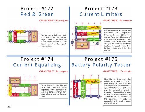
Project #172<br />
Red & Green<br />
OBJECTIVE: To compare<br />
Project #173<br />
Current Limiters<br />
OBJECTIVE: To compare<br />
Put on the switch and both<br />
LEDs will be on and equally<br />
bright. This is because the<br />
diodes are in parallel, and the<br />
electric current divides equally<br />
between them.<br />
Put on the switch and notice the<br />
difference in brightness<br />
between the two LEDs, this<br />
comes from the difference of<br />
their in-series resistance. The<br />
smaller the resistance, the<br />
stronger the electric current that<br />
is allowed to pass through. This<br />
is how resistance limits the<br />
current.<br />
Project #174<br />
Current Equalizing<br />
OBJECTIVE: To compare<br />
Project #175<br />
Battery Polarity Tester<br />
OBJECTIVE: To test the<br />
-25-<br />
Put on the switch and the two<br />
LEDs will have the same<br />
brightness. When connected in<br />
series, all components will have<br />
equal electric current through<br />
them.<br />
Use this circuit to check the<br />
polarity of a battery. Connect<br />
your battery to X and Y on the<br />
drawing using the jumper cables<br />
(your 3V battery pack (B1) can<br />
also be snapped on directly<br />
instead). If the positive (+) side<br />
of your battery is connected to<br />
X, then the red LED will be on, if<br />
the negative (–) side is<br />
connected to X then the green<br />
diode will be on.