SNAP CIRCUITSTM - Carl's Electronic Kits
SNAP CIRCUITSTM - Carl's Electronic Kits
SNAP CIRCUITSTM - Carl's Electronic Kits

Create successful ePaper yourself
Turn your PDF publications into a flip-book with our unique Google optimized e-Paper software.
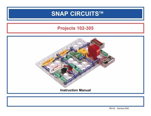
<strong>SNAP</strong> CIRCUITS TM<br />
Projects 102-305<br />
Instruction Manual<br />
REV-B Revised 2002
ADDITIONAL PARTS LIST (Colors and styles may vary) Symbols and Numbers<br />
Qty. ID Name Symbol Part # Qty. ID Name Symbol Part #<br />
3 1 1-Snap Wire 6SC30001 1 C3 10µF Capacitor 6SC30032<br />
3 2 2-Snap Wire 6SC30002 1 C4 100µF Capacitor 6SC30033<br />
1 3 3-Snap Wire 6SC30003 1 C5 470µF Capacitor 6SC30034<br />
1 4 4-Snap Wire 6SC30004 1 R2 1kΩ Resistor 6SC30041<br />
1 7 7-Snap Wire 6SC30007 1 R3 5.1kΩ Resistor 6SC30042<br />
1<br />
B1<br />
Battery Holder - uses<br />
2 1.5V type AA (not Included)<br />
6SC30019 1 R4 10kΩ Resistor 6SC30043<br />
1 A1 Antenna Coil 6SC30025 1 R5 100kΩ Resistor 6SC30044<br />
1<br />
D2<br />
Green Light Emitting<br />
Diode (LED)<br />
6SC30026 1<br />
U5<br />
High Frequency<br />
Integrated Circuit<br />
6SC30045<br />
1<br />
L2<br />
6V Lamp Socket<br />
6V Bulb (6.2V, 0.5A)<br />
Type 425 or similar<br />
6SC30027<br />
6SC30027B 1 Q1 PNP Transistor 6SC30051<br />
1 X1 Microphone 6SC30028 1 Q2 NPN Transistor 6SC30052<br />
1<br />
U4<br />
Power Amplifier<br />
Integrated Circuit<br />
6SC30029 1 RV Adjustable Resistor 6SC30053<br />
1 C1 0.02µF Capacitor 6SC30030 1 CV Variable Capacitor 6SC30054<br />
1 C2 0.1µF Capacitor 6SC30031<br />
-1-
HOW TO USE IT<br />
The <strong>Electronic</strong> Snap Circuit Kit has 204 projects. They are simple to build and<br />
understand.<br />
The snap circuit kit uses building blocks with snaps to build the different<br />
electrical and electronic circuits in the projects. Each block has a function:<br />
there are switch blocks, lamp blocks, battery blocks, different length wire<br />
blocks, etc. These blocks are in different colors and have numbers on them<br />
so that you can easily identify them. The circuit you will build is shown in color<br />
and numbers, identifying the blocks that you will use and snap together to<br />
form a circuit.<br />
For Example:<br />
This is the switch block which is green and has the marking S1 on it.<br />
OFF<br />
This is a wire block which is blue and comes in different wire lengths.<br />
This one has the number 2 , 3 , 4 , 5 , 6 , or 7 on it depending on the<br />
length of the wire connection required.<br />
There is also a 1-snap wire that is used as a spacer or for interconnection<br />
between different layers.<br />
To build each circuit, you will have two (2) power source blocks marked B1<br />
that need two (2) “AA” batteries each (not included with the snap circuit kit).<br />
A large clear plastic base grid is included with this kit to help keep the circuit<br />
block together. You will see evenly spaced posts that the different blocks snap<br />
into. You do not need this base to build your circuits, but it does help in<br />
keeping your circuit together neatly. The base has rows labeled A-G and<br />
columns labeled 1-10.<br />
Next to each part in every circuit drawing is a small number in black. This tells<br />
you which level the component is placed at. Place all parts on level 1 first,<br />
then all of the parts on level 2, then all of the parts on level 3, etc.<br />
The 2.5V bulb comes packaged separate from its socket. Install the bulb in<br />
the lamp socket L1 whenever that part is used. Do the same for the 6V bulb<br />
and socket L2 .<br />
Place the fan on the motor M1 whenever that part is used, unless the project<br />
you are building says not to use it.<br />
ON<br />
Some circuits use the jumper wires to make unusual connections. Just clip<br />
them to the metal snaps or as indicated.<br />
Note: While building the projects, be careful not to accidentally make a direct<br />
connection across the battery holder (a “short circuit”), as this will damage<br />
and/or quickly drain the batteries.<br />
Creating Your Own Circuits<br />
After building the circuits given in this booklet, you may wish to experiment on<br />
your own. Use the projects in this booklet as a guide, as many important<br />
design concepts are introduced throughout them. Every circuit will include a<br />
power source (the batteries), a resistance (which might be a resistor, lamp,<br />
motor, integrated circuit, etc.), and wiring paths between them and back. You<br />
must be careful not to create "short circuits" (very low-resistance paths across<br />
the batteries) as this will damage components and/or quickly drain your<br />
batteries. Only connect the ICs using configurations given in the projects,<br />
incorrectly doing so may damage them. Elenco <strong>Electronic</strong>s is not<br />
responsible for parts damaged due to incorrect wiring.<br />
For all of the projects given in this book, the parts may be arranged in different<br />
ways without changing the circuit. For example, the order of parts connected<br />
in series or in parallel does not matter — what matters is how combinations<br />
of these sub-circuits are arranged together.<br />
You are encouraged to tell us about new circuits you create. Upon review, we<br />
will post them with your name, age, and hometown in a special section on our<br />
website.<br />
Troubleshooting<br />
Most circuit problems are due to incorrect assembly, always double-check that<br />
your circuit exactly matches the drawing for it. Be sure that parts with<br />
positive/negative markings are positioned as per the drawing. Sometimes the<br />
light bulbs come loose, tighten them as needed. Try replacing the batteries.<br />
-2-
Project # Description Page #<br />
102 Batteries in Series 5<br />
103 Batteries in Parallel 5<br />
104 Spacey Fan 6<br />
105 Two-Transistor Light Alarm 6<br />
106 Light-Controlled Alarm 6<br />
107 Automatic Street Lamp 7<br />
108 Voice-Controlled Rays of Light 7<br />
109 Blowing Off the Electric Light 7<br />
110 Adjustable Tone Generator 8<br />
111 Photosensitive <strong>Electronic</strong> Organ 8<br />
112 <strong>Electronic</strong> Cicada 8<br />
113 Light & Sounds 9<br />
114 More Light & Sounds 9<br />
115 More Light & Sounds (II) 9<br />
116 More Light & Sounds (III) 9<br />
117 More Light & Sounds (IV) 9<br />
118 Motor Speed Detector 10<br />
119 Old-Style Typewriter 10<br />
120 Space War Sounds 11<br />
121 Space War Sounds Controlled by Light 11<br />
122 Space War Radio 12<br />
123 The Lie Detector 12<br />
124 NPN Amplifier 13<br />
125 PNP Amplifier 13<br />
126 Sucking Fan 14<br />
127 Blowing Fan 14<br />
128 PNP Collector 14<br />
129 PNP Emitter 14<br />
130 NPN Collector 15<br />
131 NPN Emitter 15<br />
132 NPN Collector - Motor 15<br />
133 NPN Emitter - Motor 15<br />
134 Buzzing in the Dark 16<br />
135 Touch Buzzer 16<br />
-3-<br />
PROJECT LISTINGS<br />
Project # Description Page #<br />
136 High Frequency Touch Buzzer 16<br />
137 High Frequency Water Buzzer 16<br />
138 Mosquito 16<br />
139 High Sensitivity Voice Doorbell 17<br />
140 Louder Doorbell 17<br />
141 Very Loud Doorbell 17<br />
142 Doorbell with Button 17<br />
143 Darkness Announcer 17<br />
144 Musical Motion Detector 17<br />
145 Radio Music Alarm 18<br />
146 Daylight Music Radio 18<br />
147 Night Music Radio 18<br />
148 Night Gun Radio 18<br />
149 Radio Gun Alarm 18<br />
150 Daylight Gun Radio 18<br />
151 Blow Off a Space War 19<br />
152 Series Lamps 19<br />
153 Parallel Lamps 19<br />
154 Fire Fan Symphony 20<br />
155 Fire Fan Symphony (II) 20<br />
156 Fan Symphony 20<br />
157 Fan Symphony (II) 20<br />
158 Police Car Symphony 21<br />
159 Police Car Symphony (II) 21<br />
160 Ambulance Symphony 21<br />
161 Ambulance Symphony (II) 21<br />
162 Static Symphony 22<br />
163 Static Symphony (II) 22<br />
164 High-Power Symphony 22<br />
165 High-Power Symphony (II) 22<br />
166 Water Detector 23<br />
167 Salt Water Detector 23<br />
168 NPN Light Control 24<br />
169 NPN Dark Control 24<br />
Project # Description Page #<br />
170 PNP Light Control 24<br />
171 PNP Dark Control 24<br />
172 Red & Green 25<br />
173 Current Limiters 25<br />
174 Current Equalizing 25<br />
175 Battery Polarity Tester 25<br />
176 Blow Off a Doorbell 26<br />
177 Blow Off a Candle 26<br />
178 Blow On a Doorbell 26<br />
179 Blow On a Candle 26<br />
180 Screaming Fan 27<br />
181 Whining Fan 27<br />
182 Light Whining 27<br />
183 More Light Whining 27<br />
184 Motor Than Won’t Start 27<br />
185 Whiner 28<br />
186 Lower Pitch Whiner 28<br />
187 Hummer 28<br />
188 Adjustable Metronome 28<br />
189 Quiet Flasher 28<br />
190 Hissing Foghorn 29<br />
191 Hissing & Clicking 29<br />
192 Video Game Engine Sound 29<br />
193 Light Alarm 30<br />
194 Brighter Light Alarm 30<br />
195 Lazy Fan 30<br />
196 Laser Light 30<br />
197 Water Alarm 31<br />
198 Drawing Resistors 31<br />
199 Pitch 32<br />
200 Pitch (II) 32<br />
201 Pitch (III) 32<br />
202 Flooding Alarm 32<br />
203 Make Your Own Battery 33
Project # Description Page #<br />
204 Make Your Own Battery (II) 33<br />
205 Make Your Own Battery (III) 33<br />
206 Tone Generator 34<br />
207 Tone Generator (II) 34<br />
208 Tone Generator (III) 34<br />
209 Tone Generator (IV) 34<br />
210 More Tone Generator 35<br />
211 More Tone Generator (II) 35<br />
212 More Tone Generator (III) 35<br />
213 Music Radio Station 36<br />
214 Alarm Radio Station 36<br />
215 Saved Electricity 36<br />
216 Motor & Lamp by Sound 37<br />
217 Fading Siren 37<br />
218 Fast Fade Siren 37<br />
219 Laser Gun with Limited Shots 38<br />
220 Symphony of Sounds 38<br />
221 Symphony of Sounds (II) 38<br />
222 Transistor Amplifiers 39<br />
223 Pressure Meter 39<br />
224 Resistance Meter 39<br />
225 Auto-Off Night-Light 40<br />
226 Discharging Caps 40<br />
227 Changing Delay Time 40<br />
228 Morse Code Generator 41<br />
229 LED Code Teacher 41<br />
230 Ghost Shriek Machine 41<br />
231 LED & Speaker 41<br />
232 Dog Whistle 41<br />
233 <strong>Electronic</strong> Golf Game 42<br />
234 Enhanced Quiet Zone Game 43<br />
235 Capacitor Charge & Discharge 43<br />
236 Sound Wave Magic 44<br />
237 Space War Amplifier 44<br />
PROJECT LISTINGS<br />
Project # Description Page #<br />
238 Trombone 45<br />
239 Race Car Engine 45<br />
240 Power Amp 46<br />
241 <strong>Electronic</strong> Kazoo 46<br />
242 AM Radio 47<br />
243 Fire Engine Symphony 48<br />
244 Fire Engine Symphony (II) 48<br />
245 Vibration or Sound Indicator 48<br />
246 Two-Finger Touch Lamp 49<br />
247 One-Finger Touch Lamp 49<br />
248 Space Battle 50<br />
249 Space Battle (II) 50<br />
250 Multi-Speed Light Fan 50<br />
251 Light & Finger Light 50<br />
252 Storing Electricity 51<br />
253 Lamp Brightness Control 51<br />
254 Electric Fan 51<br />
255 Radio Music Burglar Alarm 52<br />
256 Light Dimmer 52<br />
257 Motion Detector 53<br />
258 Fan Modulator 53<br />
259 Oscillator 0.5 - 30Hz 54<br />
260 Sound Pulse Oscillator 54<br />
261 Motion Detector (II) 54<br />
262 Motor Rotation 55<br />
263 Motor Delay Fan 55<br />
264 Motor Delay Fan (II) 55<br />
265 High Pitch Bell 56<br />
266 Steamboat Whistle 56<br />
267 Steamship 56<br />
268 Steamship Horn 56<br />
269 Noise-Activated Burglar Alarm 57<br />
270 Motor-Activated Burglar Alarm 57<br />
271 Light-Activated Burglar Alarm 57<br />
Project # Description Page #<br />
272 Optocoupler with LED 58<br />
273 Optocoupler with Speaker 58<br />
274 Pressure Alarm 59<br />
275 Power Microphone 59<br />
276 LED Fan Rotation Indicator 60<br />
277 Space War Sounds with LED 60<br />
278 Sound Mixer 61<br />
279 Sound Mixer Fan Driver 61<br />
280 Electric Fan Stopped by Light 62<br />
281 Motor & Lamp 62<br />
282 Start-Stop Delay 63<br />
283 Mail Notifying System 63<br />
284 Mail Notifying <strong>Electronic</strong> Bell 64<br />
285 Mail Notifying <strong>Electronic</strong> Fan 64<br />
286 Twice-Amplified Oscillator 64<br />
287 Quick Flicking LED 64<br />
288 AM Radio with Transistors 65<br />
289 AM Radio (II) 65<br />
290 Music Amplifier 66<br />
291 Delayed Action Lamp 66<br />
292 Delayed Action Fan 66<br />
293 Police Siren Amplifier 67<br />
294 Lasting Doorbell 67<br />
295 Lasting Clicking 67<br />
296 Leaky Capacitor 68<br />
297 Transistor Fading Siren 68<br />
298 Fading Doorbell 68<br />
299 Blowing Space War Sounds 69<br />
300 Adjustable Time Delay Lamp 69<br />
301 Adjustable Time Delay Fan 69<br />
302 Adjustable Time Delay Lamp (II) 70<br />
303 Adjustable Time Delay Fan (II) 70<br />
304 Watch Light 70<br />
305 Delayed Bedside Fan 70<br />
-4-
Project #102<br />
Batteries in Series<br />
OBJECTIVE: To show the increase in voltage when<br />
When you close the slide switch (S1), current flows from the batteries<br />
through the slide switch (S1), the 1kΩ resistor (R1), the LED (D1),<br />
through the LED (D2), and back to the second group of batteries (B1).<br />
Notice how both LEDs are lit. The voltage is high enough to turn on<br />
both LEDs when the batteries are connected in series. If only one set<br />
of batteries is used, the LEDs will not light up.<br />
Some devices use only one 1.5 volt battery, but they make hundreds<br />
of volts electronically from this small source. A flash camera is an<br />
example of this.<br />
Project #103<br />
Batteries in Parallel<br />
OBJECTIVE: To show how batteries in parallel are<br />
Build the circuit shown on the left by placing all of the parts with a black<br />
1 next to them on the board first. Then, assemble the parts marked with<br />
a 2 (including the 1-snap wire at base grid location C5). Finally, place a<br />
2-snap wire at grid location C4, leaving the other end of it unconnected as<br />
shown.<br />
The light should be on and the brightness of the lamp will depend on the<br />
quality of the batteries in the holder on the left. Put weak batteries in the<br />
left holder and strong batteries in the right holder. Snap in the loose end<br />
of the 2-snap wire to grid point C5. Now the lamp will get brighter as the<br />
fresh batteries take over and supply the current to the light.<br />
Batteries are placed in parallel when the voltage is adequate but the load<br />
needs more current than one group of batteries can supply. Think of each<br />
battery as a storage tank that supplies water. If you put two in parallel, you<br />
can get more water (current), but the pressure (voltage) stays the same.<br />
-5-
Project #104 Spacey Fan<br />
OBJECTIVE: To build a fan with space war sounds that<br />
Project #105<br />
Two-Transistor Light Alarm<br />
Place the fan onto the motor.<br />
Space war sounds are heard if<br />
light shines on the<br />
photosensitive resistor OR if you<br />
press the press switch (S2), the<br />
fan may start to spin, but will only<br />
get to high speed if you do<br />
BOTH. Try various combinations<br />
of shining light and holding down<br />
the press switch.<br />
This light alarm circuit uses two<br />
(2) transistors and both sets of<br />
batteries. Build the circuit with<br />
the jumper connected as shown,<br />
and turn it on. Nothing happens.<br />
Break the jumper connection<br />
and the light turns on. You could<br />
replace the jumper with a longer<br />
wire and run it across a doorway<br />
to signal an alarm when<br />
someone enters.<br />
Project #106<br />
Light-Controlled Alarm<br />
OBJECTIVE: To show how light is used to turn an<br />
The alarm will sound, as long as light is present. Slowly cover the<br />
photosensitive resistor (RP), and the volume goes down. If you turn<br />
off the lights, the alarm will stop. The amount of light changes the<br />
resistance of the photosensitive resistor (less light means more<br />
resistance). The photosensitive resistor and transistor (Q2) act like a<br />
dimmer switch, adjusting the voltage applied to the alarm.<br />
This type of circuit is used in alarm systems to detect light. If an<br />
intruder turned on a light or hit the sensor with a flashlight beam, the<br />
alarm would trigger and probably force the intruder to leave.<br />
-6-
Project #107<br />
Automatic Street Lamp<br />
OBJECTIVE: To show how light is used to control a<br />
Press the press switch (S2) on and set the adjustable resistor (RV) so<br />
the lamp just lights. Slowly cover the photosensitive resistor (RP) and<br />
the lamp brightens. If you place more light at the photosensitive<br />
resistor the light dims.<br />
This is an automatic street lamp that you can turn on by a certain<br />
darkness and turn off by a certain brightness. This type of circuit is<br />
installed on many outside lights and forces them to turn off and save<br />
electricity. They also come on when needed for safety.<br />
Project #108<br />
Voice-Controlled Rays of Light<br />
Project #109<br />
Blowing Off the Electric Light<br />
Turn the slide switch<br />
(S1) on. There will be<br />
only a weak light<br />
emitting from the green<br />
LED. By blowing on<br />
the mic (X1) or putting<br />
it near a radio or TV<br />
set, the green LED will<br />
emit light, and its<br />
brightness changes as<br />
the loudness changes.<br />
Install the parts. The<br />
lamp (L1) will be on. It<br />
will be off as long as<br />
you blow on the mic<br />
(X1). Speaking loud<br />
into the mic will<br />
change the brightness<br />
of the lamp.<br />
-7-
Project #110<br />
Adjustable Tone Generator<br />
OBJECTIVE: To show how resistor values change the<br />
Turn on the slide switch (S1), the speaker (SP) will sound and the LED<br />
(D2) will light. Adjust the resistor (RV) to make different tones. In an<br />
oscillator circuit, changing the values of resistors or capacitors can<br />
vary the output tone or pitch.<br />
Project #111<br />
Photosensitive <strong>Electronic</strong> Organ<br />
OBJECTIVE: To show how resistor values change the<br />
Project #112<br />
<strong>Electronic</strong> Cicada<br />
OBJECTIVE: To show how capacitors in parallel<br />
Use the circuit from Project 110 shown above. Replace the 100kΩ (R5)<br />
with the photosensitive resistor (RP). Turn on the slide switch (S1). The<br />
speaker (SP) will sound and the LED (D2) will light. Move your hand up<br />
and down over the photosensitive resistor (RP) and the frequency<br />
changes. Decreasing the light on the photosensitive resistor increases<br />
the resistance and causes the circuit to oscillate at a lower frequency.<br />
Notice that the LED flashes also at the same frequency as the sound.<br />
By using your finger, see if you can vary the sounds enough to make this<br />
circuit sound like an organ playing.<br />
Use the circuit from Project 110 shown above, replace the<br />
photosensitive resistor (RP) back to the 100kΩ (R5) resistor. Place the<br />
0.02µF (C1) on top of the whistle chip (WC). Place the slide switch (S1)<br />
on and adjust the resistor (RV). The circuit produces the sound of the<br />
cicada insect. By placing the 0.02µF on top of the whistle chip, the<br />
circuit oscillates at a lower frequency. Notice that the LED flashes also<br />
at the same frequency.<br />
It is possible to pick resistors and capacitors that will make the pitch<br />
higher than humans can hear. Many animals, however, can hear these<br />
tones. For example, a parakeet can hear tones up to 50,000 cycles per<br />
second, but a human can only hear to 20,000.<br />
-8-
Project #113<br />
Light & Sounds<br />
Turn on the slide switch (S1). A police siren is heard and the lamp<br />
lights.<br />
Project #114<br />
More Light &<br />
Sounds<br />
Project #115<br />
More Light &<br />
Sounds (II)<br />
Project #116<br />
More Light &<br />
Sounds (III)<br />
Project #117<br />
More Light &<br />
Sounds (IV)<br />
OBJECTIVE: To show a<br />
variation of the circuit in<br />
OBJECTIVE: To show a<br />
variation of the circuit in<br />
OBJECTIVE: To show a<br />
variation of the circuit in<br />
OBJECTIVE: To show a<br />
variation of the circuit in<br />
Modify the last circuit by<br />
connecting points X and Y. The<br />
circuit works the same way but<br />
now it sounds like a machine<br />
gun.<br />
Now remove the connection<br />
between X and Y and then make<br />
a connection between T and U.<br />
Now it sounds like a fire engine.<br />
Now remove the connection<br />
between T and U and then make<br />
a connection between U and Z.<br />
Now it sounds like an ambulance.<br />
Now remove the connections<br />
between U and Z and between V<br />
and W, then make a connection<br />
between T and U. Now it sounds<br />
like a water faucet.<br />
-9-
Project #118<br />
Motor Speed Detector<br />
OBJECTIVE: To show how to make electricity in one<br />
When building the circuit, be sure to position the motor with the<br />
positive (+) side snapped to the 470µF capacitor (C5). Turn on the<br />
slide switch (S1), nothing will happen. It is a motor speed detector,<br />
and the motor isn't moving. Watch the LED (D2) and give the motor a<br />
good spin CLOCKWISE with your fingers (don't use the fan blade); you<br />
should see a flash of light. The faster you spin the motor, the brighter<br />
the flash will be. As a game, see who can make the brightest flash.<br />
Now try spinning the motor in the opposite direction (counterclockwise)<br />
and see how bright the flash is — it won't flash at all<br />
because the electricity it produces, flows in the wrong direction and<br />
won't activate the diode. Flip the motor around (positive (+) side<br />
snapped to the 3-snap wire) and try again. Now the diode lights only<br />
if you spin the motor counter-clockwise.<br />
Project #119<br />
Old-Style Typewriter<br />
Turn on the slide switch (S1), nothing will happen. Turn the motor<br />
slowly with your fingers (don’t use the fan blade), you will hear a<br />
clicking that sounds like an old-time manual typewriter keystrokes.<br />
Spin the motor faster and the clicking speeds up accordingly.<br />
This circuit works the same if you spin the motor in either direction<br />
(unlike the Motor Speed Detector project).<br />
By spinning the motor with your fingers, the physical effort you exert is<br />
converted into electricity. In electric power plants, steam is used to<br />
spin large motors like this, and the electricity produced is used to run<br />
everything in your town.<br />
-10-
Project #120<br />
Space War Sounds<br />
OBJECTIVE: To build a circuit that produces multiple<br />
Set the slide switch (S1) to the OFF position. Press the press switch<br />
(S2) down and a space sound will be played. If you hold the press<br />
switch down the sound repeats. Press the press switch again and a<br />
different sound is played. Keep pressing the press switch to hear all<br />
the different sounds.<br />
Next, set the slide switch (S1) to ON position. One of the sounds will<br />
be played continuously. Turn the switch off and then back on. A<br />
different sound is played. Keep pressing the press switch to hear all<br />
the different combinations of sounds.<br />
The space war integrated circuit has “logic” built into its circuitry that<br />
allows it to switch between many different sounds.<br />
Project #121<br />
Space War Sounds Controlled By Light<br />
OBJECTIVE: To change the sounds of a multiple space<br />
Modify the preceding circuit to look like the one shown on the left.<br />
The space war IC (U3) will play a sound continuously. Block the light<br />
from the photosensitive resistor (RP) with your hand. The sound will<br />
stop. Remove your hand and a different sound is played. Wave your<br />
hand over the photosensitive resistor to hear all the different sounds.<br />
Press the press switch down and now two space war sounds are<br />
played. If you hold the press switch down the sound repeats. Press<br />
the press switch again and a different sound is played. Keep pressing<br />
the press switch to hear all the different combinations of sounds.<br />
-11-
Project #122<br />
Space War Radio<br />
OBJECTIVE: To transmit Space War sounds to a AM<br />
Place the circuit next to an AM radio. Tune the radio so no stations are<br />
heard and turn on the slide switch (S1). You should hear the space war<br />
sounds on the radio. The red LED should also be lit. Adjust the<br />
variable capacitor (CV) for the loudest signal.<br />
You have just performed the experiment that took Marconi (who<br />
invented the radio) a lifetime to invent. The technology of radio<br />
transmission has expanded to the point that we take it for granted.<br />
There was a time, however, when news was only spread by word of<br />
mouth.<br />
Project #123<br />
The Lie Detector<br />
OBJECTIVE: To show how sweat makes a better<br />
Turn on the slide switch (S1) and place your finger across point A and<br />
B. The speaker will output a tone and the LED will flash at the same<br />
frequency. Your finger acts as a conductor connecting points A and B.<br />
When a person is lying, one thing the body starts to do is sweat. The<br />
sweat makes the finger a better conductor by reducing its resistance.<br />
As the resistance drops, the frequency of the tone increases. Lightly<br />
wet your finger and place it across the two points again. Both the<br />
output tone and LED flashing frequency increase. Now change the<br />
wetness of your finger by drying it and see how it affects the circuit.<br />
This is the same principle used in lie detectors that are sold<br />
commercially.<br />
-12-
Project #124<br />
NPN Amplifier<br />
There are three connection points on an NPN transistor, called base<br />
(marked B), emitter (marked E), and collector (marked C). When a<br />
small electric current flows from the base to the emitter, a larger<br />
(amplified) current will flow from the collector to the emitter. Build the<br />
circuit and slowly move up the adjustable resistor control. When the<br />
LED becomes bright, the lamp will also turn on and will be much<br />
brighter.<br />
Project #125<br />
PNP Amplifier<br />
The PNP transistor is similar to the NPN transistor in Project 166<br />
except that the electric currents flow in the opposite directions. When<br />
a small electric current flows from the emitter to the base, a larger<br />
(amplified) current will flow from the emitter to the collector. Build the<br />
circuit and slowly move up the adjustable resistor control. When the<br />
LED becomes bright, the lamp will also turn on and will be much<br />
brighter.<br />
-13-
Project #126<br />
Sucking Fan<br />
Build the circuit, and be sure to orient the motor with<br />
the positive (+) side down as shown. Turn it on, and set<br />
the adjustable resistor for the fan speed you like best.<br />
If you set the speed too fast then the fan may fly off the<br />
motor. Due to the shape of the fan blades and the<br />
direction the motor spins, air is sucked into the fan and<br />
towards the motor. Try holding a piece of paper just<br />
above the fan to prove this. If this suction is strong<br />
enough then it can lift the fan blades, just like in a<br />
helicopter.<br />
The fan will not move on all settings of the resistor,<br />
because the resistance is too high to overcome friction<br />
in the motor.<br />
Project #127<br />
Blowing Fan<br />
OBJECTIVE: To build a fan<br />
Modify the circuit from Project 126 by<br />
reversing the position of the motor (so<br />
the positive (+) side is towards the<br />
PNP (Q1). Turn it on, and set the<br />
adjustable resistor for the fan speed<br />
you like best. Set it for full speed and<br />
see if the fan flies off - it won’t! The<br />
fan is blowing air upward now! Try<br />
holding a piece of paper just above<br />
the fan to prove this.<br />
Project #128 PNP Collector<br />
OBJECTIVE: To<br />
demonstrate adjusting<br />
the gain of a transistor<br />
Build the circuit and vary<br />
the lamp brightness with<br />
the adjustable resistor, it<br />
will be off for most of the<br />
resistor’s range. The point<br />
on the PNP that the lamp is<br />
connected to (point E4 on<br />
the base grid) is called the<br />
collector, hence the name<br />
for this project.<br />
Project #129 PNP Emitter<br />
OBJECTIVE:<br />
To compare<br />
Compare this circuit to<br />
that in Project 128. The<br />
maximum lamp<br />
brightness is less here<br />
because the lamp<br />
resistance reduces the<br />
emitter-base current,<br />
which contacts the<br />
emitter-collector current<br />
(as per Project 25). The<br />
point on the PNP that<br />
the lamp is now<br />
connected to (grid point<br />
C4) is called the emitter.<br />
-14-
Project #130<br />
NPN Collector<br />
OBJECTIVE: To compare<br />
Project #131<br />
NPN Emitter<br />
OBJECTIVE: To compare<br />
Compare this circuit to that in<br />
Project 128, it is the NPN<br />
transistor version and works the<br />
same way. Which circuit makes<br />
the lamp brighter? (They are<br />
about the same because both<br />
transistors are made from the<br />
same materials).<br />
Compare this circuit to that in<br />
Project 129. It is the NPN<br />
transistor version and works the<br />
same way. The same principles<br />
apply here as in Projects 128-<br />
130, so you should expect it to<br />
be less bright than 130 but as<br />
bright as 129.<br />
Project #132<br />
NPN Collector - Motor<br />
OBJECTIVE: To compare<br />
Project #133<br />
NPN Emitter - Motor<br />
OBJECTIVE: To compare<br />
This is the same circuit as in<br />
Project 130, except that it has<br />
the motor (M1) instead of the<br />
lamp. Place the motor with the<br />
positive (+) side touching the<br />
NPN and put the fan on it.<br />
This is the same circuit as in<br />
Project 131, except that it has<br />
the motor (M1) instead of the<br />
lamp. Place the motor with the<br />
positive (+) side down and put<br />
the fan on it. Compare the fan<br />
speed to that in Project 132.<br />
Just as the lamp was dimmer in<br />
the emitter configuration, the<br />
motor is not as fast now.<br />
-15-
Project #134<br />
Buzzing in<br />
the Dark<br />
OBJECTIVE: To make a circuit<br />
Project #135<br />
Touch Buzzer<br />
OBJECTIVE: To build a human<br />
This circuit makes a high-frequency<br />
screaming sound when light shines on<br />
the photosensitive resistor, and makes a<br />
buzzing sound when you shield the<br />
photosensitive resistor.<br />
Remove the photosensitive resistor (RP) from<br />
the circuit in Project 134 and instead touch<br />
your fingers across where it used to be<br />
(points B1 and D1 on the grid) to hear a cute<br />
buzzing sound.<br />
The circuit works because of the resistance in<br />
your body. If you put back the photosensitive<br />
resistor and partially cover it, you should be<br />
able to make the same resistance your body<br />
did, and get the same sound.<br />
Project #136<br />
High Frequency<br />
Touch Buzzer<br />
OBJECTIVE: To build a high<br />
Project #137<br />
High Frequency<br />
Water Buzzer<br />
OBJECTIVE: To build a high<br />
Project #138<br />
Mosquito<br />
OBJECTIVE: To make a buzz like a<br />
Replace the speaker (SP) with the 6V Lamp<br />
(L2). Now touching your fingers between B1<br />
and D1 creates a quieter but more pleasant<br />
buzzing sound.<br />
Now connect two (2) jumpers to points B1 and<br />
D1 (that you were touching with your fingers)<br />
and place the loose ends into a cup of water.<br />
The sound will not be much different now,<br />
because your body is mostly water and so the<br />
circuit resistance has not changed much.<br />
Place the photosensitive resistor (RP) into the<br />
circuit in Project 137 across where you were<br />
connecting the jumpers (points B1 and D1 on<br />
the grid, and as shown in Project 134). Now<br />
the buzz sounds like a mosquito.<br />
-16-
Project #139<br />
High<br />
Sensitivity<br />
Voice Doorbell<br />
OBJECTIVE: To build a<br />
highly sensitive voice-<br />
Project #140<br />
Louder<br />
Doorbell<br />
OBJECTIVE: To build a<br />
loud highly sensitive voice-<br />
Build the circuit and wait until the<br />
sound stops. Clap or talk loud a<br />
few feet away and the music<br />
plays again. The microphone<br />
(X1) is used here because it is<br />
very sensitive.<br />
Replace the 6V lamp (L2) with<br />
the antenna coil (A1), the sound<br />
is louder now.<br />
Project #141<br />
Very Loud<br />
Doorbell<br />
Project #142<br />
Doorbell<br />
with Button<br />
Project #143<br />
Darkness<br />
Announcer<br />
Project #144<br />
Musical<br />
Motion Detector<br />
OBJECTIVE: To build a<br />
very loud highly sensitive<br />
OBJECTIVE: To build a<br />
OBJECTIVE: To play OBJECTIVE: To detect<br />
when someone spins the<br />
Replace the antenna coil (A1)<br />
with the speaker (SP), the sound<br />
is much louder now.<br />
Replace the microphone (X1)<br />
with the press switch (S2) and<br />
wait until the music stops. Now<br />
you have to press the slide switch<br />
(S1) to activate the music, just<br />
like the doorbell on your house.<br />
Replace the press switch (S2)<br />
with the photosensitive resistor<br />
(RP) and wait until the sound<br />
stops. If you cover the<br />
photosensitive resistor now the<br />
music will play once, signaling<br />
that it has gotten dark. If the<br />
speaker (SP) is too loud then you<br />
may replace it with the antenna<br />
coil (A1).<br />
Replace the photosensitive<br />
resistor (RP) with the motor (M1),<br />
oriented in either direction. Now<br />
spinning the motor will re-activate<br />
the music.<br />
-17-
Project #145<br />
Radio Music<br />
Alarm<br />
OBJECTIVE: To build a radio music<br />
You need an AM radio for this project. Build the<br />
circuit on the left and turn on the switch. Place<br />
it next to your AM radio and tune the radio<br />
frequency to where no other station is<br />
transmitting. Then, tune the adjustable<br />
capacitor (CV) until your music sounds best on<br />
the radio. Now connect a jumper wire between<br />
X and Y on the drawing, the music stops.<br />
If you remove the jumper now, the music will<br />
play indicating your alarm wire has been<br />
triggered. You could use a longer wire and wrap<br />
it around a bike, and use it as a burglar alarm!<br />
Project #146<br />
Daylight<br />
Music Radio<br />
OBJECTIVE: To build a<br />
light-controlled radio<br />
Remove the jumper wire.<br />
Replace the 100kΩ resistor (R5)<br />
with the photosensitive resistor<br />
(RP). Now your AM radio will<br />
play music as long as there is<br />
light in the room.<br />
Project #147<br />
Night Music<br />
Radio<br />
Project #148<br />
Night Gun<br />
Radio<br />
Project #149<br />
Radio Gun<br />
Alarm<br />
Project #150<br />
Daylight Gun<br />
Radio<br />
OBJECTIVE: To build a<br />
dark-controlled radio<br />
OBJECTIVE: To build a<br />
dark-controlled radio<br />
OBJECTIVE: To build a<br />
OBJECTIVE: To build a<br />
light-controlled radio<br />
Put the 100kΩ resistor back in as<br />
before and instead connect the<br />
photosensitive resistor between<br />
X and Y (you also need a 1-snap<br />
and a 2-snap wire to do this).<br />
Now your radio plays music when<br />
it is dark.<br />
Replace the music IC (U1) with<br />
the alarm IC (U2). Now your<br />
radio plays the sound of a<br />
machine gun when it is dark.<br />
Remove the photosensitive<br />
resistor. Now connect a jumper<br />
wire between X and Y on the<br />
drawing.<br />
If you remove the jumper now,<br />
the machine gun sound will play<br />
on the radio indicating your alarm<br />
wire has been triggered.<br />
Remove the jumper wire.<br />
Replace the 100kΩ resistor (R5)<br />
with the photosensitive resistor<br />
(RP). Now your AM radio will<br />
play the machine gun sound as<br />
long as there is light in the room.<br />
-18-
Project #151<br />
Blow Off a Space War<br />
Build the circuit and turn it on,<br />
you hear a space war. Since it is<br />
loud and annoying, try to shut it<br />
off by blowing into the<br />
microphone (X1). Blowing hard<br />
into the microphone stops the<br />
sound, and then it starts again.<br />
Project #152<br />
Series Lamps<br />
Project #153<br />
Parallel Lamps<br />
Turn on the slide<br />
switch (S1) and both<br />
lamps will light. If one<br />
of the bulbs is broken<br />
then neither will be on,<br />
because the lamps are<br />
in series. An example<br />
of this is the strings of<br />
small Christmas lights;<br />
if one bulb is damaged<br />
then the entire string<br />
does not work.<br />
Turn on the slide<br />
switch (S1) and both<br />
lamps will light. If one<br />
of the bulbs is broken<br />
then the other will still<br />
be on, because the<br />
lamps are in parallel.<br />
An example of this is<br />
most of the lights in<br />
your house; if a bulb is<br />
broken on one lamp<br />
then the other lamps<br />
are not affected.<br />
-19-
Project #154<br />
Project #156<br />
Fire Fan Symphony<br />
OBJECTIVE: To combine<br />
sounds from the music, alarm,<br />
Build the circuit shown and add the<br />
jumper to complete it. Note that in<br />
one place two (2) single snaps are<br />
stacked on top of each other. Also,<br />
note that there is a 2-snap wire on<br />
layer 2 that does not connect with a<br />
4-snap wire that runs over it on layer<br />
4 (both touch the music IC). Turn it<br />
on and press the press switch (S2)<br />
several times and wave your hand<br />
over the photosensitive resistor (RP)<br />
to hear the full spectrum of sounds<br />
that this circuit can create. Have fun!<br />
Fan Symphony<br />
OBJECTIVE: To combine<br />
sounds from the music, alarm,<br />
Project #155<br />
Fire Fan<br />
Symphony (II)<br />
OBJECTIVE:<br />
The preceding circuit may be too<br />
loud, so replace the speaker (SP)<br />
with the whistle chip (WC).<br />
Project #157<br />
Fan<br />
Symphony (II)<br />
OBJECTIVE:<br />
Modify the circuit from Project 154 to<br />
match the circuit shown on the left.<br />
The only differences are the<br />
connections around the alarm IC. It<br />
works the same way.<br />
The preceding circuit may be too<br />
loud, so replace the speaker (SP)<br />
with the whistle chip (WC).<br />
-20-
Project #158<br />
Project #160<br />
Police Car Symphony<br />
OBJECTIVE: To combine<br />
sounds from the integrated<br />
Build the circuit shown and add the two (2)<br />
jumper wires to complete it. Note that in one<br />
place two (2) single snaps are stacked on<br />
top of each other. Turn it on and press the<br />
press switch (S2) several times and wave<br />
your hand over the photosensitive resistor<br />
(RP) to hear the full spectrum of sounds that<br />
this circuit can create. Have fun!<br />
Do you know why the antenna (A1) is used<br />
in this circuit? It is being used as just a 3-<br />
snap wire, because it acts like an ordinary<br />
wire in low frequency circuits such as this.<br />
Without it, you don't have enough parts to<br />
build this complex circuit.<br />
Ambulance Symphony<br />
OBJECTIVE: To combine<br />
sounds from the music, alarm,<br />
Project #159<br />
Police Car<br />
Symphony (II)<br />
OBJECTIVE:<br />
The preceding circuit may be too<br />
loud, so replace the speaker (SP)<br />
with the whistle chip (WC).<br />
Project #161<br />
Ambulance<br />
Symphony (II)<br />
OBJECTIVE:<br />
Modify the circuit from Project 158 to<br />
match the circuit shown on the left.<br />
The only differences are the<br />
connections around the alarm IC. It<br />
works the same way.<br />
The preceding circuit may be too<br />
loud, so replace the speaker (SP)<br />
with the whistle chip (WC).<br />
-21-
Project #162<br />
Static Symphony<br />
OBJECTIVE: To combine<br />
sounds from the integrated<br />
Project #163<br />
Static<br />
Symphony (II)<br />
OBJECTIVE: See Project<br />
Build the circuit shown and add the<br />
jumper wire to complete it. Note that<br />
in one place 2 single snaps are<br />
stacked on top of each other. Turn it<br />
on and press the press switch several<br />
times and wave your hand over the<br />
photosensitive resistor (RP) to hear<br />
the full spectrum of sounds that this<br />
circuit can create. Have fun!<br />
Project #164 High-Power Symphony<br />
OBJECTIVE: To combine<br />
sounds from the music, alarm,<br />
Build the circuit shown and place the<br />
fan on the motor. Be sure to use the<br />
6V lamp, not the 2.5V one. Also,<br />
note that there is a 2-snap wire on<br />
layer 2 that does not connect with a<br />
4-snap wire that runs over it on layer<br />
4 (both touch the music IC). Turn it<br />
on and press the press switch (S2)<br />
several times and wave your hand<br />
over the photosensitive resistor (RP)<br />
to hear the full spectrum of sounds<br />
that this circuit can create. Have fun!<br />
The preceding circuit may be too<br />
loud, so replace the speaker (SP)<br />
with the whistle chip (WC).<br />
Do you know why the antenna<br />
(A1) is used in this circuit? It is<br />
being used as just a 3-snap wire,<br />
because it acts like an ordinary<br />
wire in low frequency circuits<br />
such as this. Without it you don’t<br />
have enough parts to build this<br />
complex circuit.<br />
Project #165<br />
High-Power<br />
Symphony (II)<br />
OBJECTIVE: See Project<br />
The preceding circuit may be too<br />
loud, so replace the speaker (SP)<br />
with the whistle chip (WC). In<br />
some cases, the fan may now be<br />
louder than the sound, so<br />
disconnect the jumper from F3 to<br />
G3 if desired.<br />
-22-
Project #166<br />
Water Detector<br />
Build the circuit at left and connect the two jumpers to it, but leave the<br />
loose ends of the jumpers lying on the table initially. Turn on the switch<br />
- the LED (D1) will be dark because the air separating the jumpers has<br />
very high resistance. Touch the loose jumper ends to each other and<br />
the LED will be bright, because with a direct connection there is no<br />
resistance separating the jumpers.<br />
Now take the loose ends of the jumpers and place them in a cup of<br />
water, without letting them touch each other. The LED should be dimly<br />
lit, indicating you have detected water!<br />
For this experiment, your LED brightness may vary depending upon<br />
your local water supply. Pure water (like distilled water) has very high<br />
resistance, but drinking water has impurities mixed in that increase<br />
electrical conduction.<br />
Project #167<br />
Salt-Water Detector<br />
OBJECTIVE: To show how adding salt to water<br />
Place the jumpers in a cup of water as in the preceding project; the<br />
LED (D1) should be dimly lit. Slowly add salt to the water and see how<br />
the LED brightness changes, mix it a little so it dissolves. It will slowly<br />
become very bright as you add more salt. You can use this bright LED<br />
condition as a salt-water detector! You can then reduce the LED<br />
brightness by adding more water to dilute the salt.<br />
Take another cup of water and try adding other household substances<br />
like sugar to see if they increase the LED brightness as the salt did.<br />
-23-
Project #168<br />
NPN Light Control<br />
OBJECTIVE: To compare<br />
Project #169<br />
NPN Dark Control<br />
OBJECTIVE: To compare<br />
Put on the switch, the<br />
brightness of the LED depends<br />
on how much light shines on the<br />
photosensitive resistor. The<br />
resistance drops as more light<br />
shines, allowing more current to<br />
the NPN.<br />
Put on the switch, the<br />
brightness of the LED depends<br />
on how LITTLE light shines on<br />
the photosensitive resistor. The<br />
resistance drops as more light<br />
shines, diverting current away<br />
from the NPN.<br />
Project #170<br />
PNP Light Control<br />
OBJECTIVE: To compare<br />
Project #171<br />
PNP Dark Control<br />
OBJECTIVE: To compare<br />
Put on the switch, the<br />
brightness of the LED depends<br />
on how much light shines on the<br />
photosensitive resistor. The<br />
resistance drops as more light<br />
shines, allowing more current<br />
through the PNP. This is similar<br />
to the NPN circuit above.<br />
Put on the switch, the<br />
brightness of the LED depends<br />
on how LITTLE light shines on<br />
the photosensitive resistor. The<br />
resistance drops as more light<br />
shines, so more current gets to<br />
the 100kΩ resistor from the<br />
photosensitive resistor path and<br />
less from the PNP-diode path.<br />
This is similar to the NPN circuit<br />
above.<br />
-24-
Project #172<br />
Red & Green<br />
OBJECTIVE: To compare<br />
Project #173<br />
Current Limiters<br />
OBJECTIVE: To compare<br />
Put on the switch and both<br />
LEDs will be on and equally<br />
bright. This is because the<br />
diodes are in parallel, and the<br />
electric current divides equally<br />
between them.<br />
Put on the switch and notice the<br />
difference in brightness<br />
between the two LEDs, this<br />
comes from the difference of<br />
their in-series resistance. The<br />
smaller the resistance, the<br />
stronger the electric current that<br />
is allowed to pass through. This<br />
is how resistance limits the<br />
current.<br />
Project #174<br />
Current Equalizing<br />
OBJECTIVE: To compare<br />
Project #175<br />
Battery Polarity Tester<br />
OBJECTIVE: To test the<br />
-25-<br />
Put on the switch and the two<br />
LEDs will have the same<br />
brightness. When connected in<br />
series, all components will have<br />
equal electric current through<br />
them.<br />
Use this circuit to check the<br />
polarity of a battery. Connect<br />
your battery to X and Y on the<br />
drawing using the jumper cables<br />
(your 3V battery pack (B1) can<br />
also be snapped on directly<br />
instead). If the positive (+) side<br />
of your battery is connected to<br />
X, then the red LED will be on, if<br />
the negative (–) side is<br />
connected to X then the green<br />
diode will be on.
Project #176<br />
Blow Off a Doorbell<br />
OBJECTIVE: To turn off a<br />
Build the circuit and turn it on, music<br />
plays. Since it is loud and annoying,<br />
try to shut it off by blowing into the<br />
microphone (X1). Blowing hard into<br />
the microphone stops the music, and<br />
then it starts again.<br />
Project #177<br />
Blow Off a<br />
Candle<br />
OBJECTIVE: To turn off a<br />
Replace the speaker (SP) with<br />
the light emitting diode (D1), with<br />
the positive (+) side on top.<br />
Blowing hard into the<br />
microphone stops the turns off<br />
the light briefly, and then it comes<br />
on again.<br />
Project #178<br />
Blow On a Doorbell<br />
OBJECTIVE: To turn on a<br />
Build the circuit and turn it on, music<br />
plays for a few moments and then<br />
stops. Blow into the microphone (X1)<br />
and it plays; it plays as long as you<br />
keep blowing.<br />
Project #179<br />
Blow On a<br />
Candle<br />
OBJECTIVE: To turn on a<br />
Replace the speaker (SP) with<br />
the LED (D1), with the positive<br />
(+) side on top. Blowing into the<br />
microphone turns on the light,<br />
and then it goes off again.<br />
-26-
Project #180<br />
Screaming Fan<br />
OBJECTIVE: To have an<br />
adjustable resistance control a<br />
Project #181<br />
Whining Fan<br />
OBJECTIVE: To make different<br />
Build the circuit on the left; note that the<br />
0.1µF capacitor (C2) is above the NPN<br />
(Q2). Turn on the switch and move the<br />
setting on the adjustable resistor across<br />
its range. You hear screaming sounds<br />
and the fan spins.<br />
Replace the 0.1µF capacitor (C2) with the<br />
0.02µF capacitor (C1). The sounds are now a<br />
high-pitch whine and the motor starts a little<br />
sooner.<br />
Project #182<br />
Light Whining<br />
OBJECTIVE: To make different<br />
Project #183<br />
More Light<br />
Whining<br />
OBJECTIVE: To make different<br />
Project #184<br />
Motor That<br />
Won’t Start<br />
OBJECTIVE: To make different<br />
Replace the 3-snap wire at the upper-left of<br />
the circuit (points A1 and A3 on the base grid)<br />
with the photosensitive resistor (RP), and<br />
wave your hand over it. The whining sound<br />
has changed a little and can now be<br />
controlled by light.<br />
Replace the 0.02µF capacitor (C1) with the<br />
0.1µF capacitor (C2). The sounds are lower<br />
in frequency and you can't make the fan spin<br />
now.<br />
Replace the 0.1µF capacitor (C2) with the<br />
10µF capacitor (C3), put the positive (+) side<br />
towards the left). It now makes clicking<br />
sounds and the fan moves only in small<br />
bursts, like a motor that won’t start.<br />
-27-
Project #185<br />
Whiner<br />
OBJECTIVE: To build a circuit<br />
Project #186<br />
Lower Pitch<br />
Whiner<br />
OBJECTIVE: To show how adding<br />
Build the circuit, turn it on, and move the<br />
setting on the adjustable resistor. It<br />
makes a loud, annoying whine sound.<br />
The green LED (D2) appears be on, but it<br />
is actually flashing at a very fast rate.<br />
Place the 0.02µF capacitor (C1) above the<br />
whistle chip (WC) and vary the adjustable<br />
resistance again. The frequency (or pitch) of<br />
the whine has been reduced by the added<br />
capacitance and it sounds more like music<br />
now.<br />
Project #187<br />
Hummer<br />
OBJECTIVE: To show how adding<br />
Project #188<br />
Adjustable<br />
Metronome<br />
OBJECTIVE: To build an<br />
Project #189<br />
Quiet Flasher<br />
OBJECTIVE: To make a blinking<br />
Now place the 0.1µF capacitor (C2) above<br />
the whistle chip (WC) and vary the adjustable<br />
resistor again. The frequency (or pitch) of the<br />
whine has been reduced by the greater<br />
added capacitance and it sounds more like a<br />
hum now.<br />
Now place the 10µF capacitor (C3, in either<br />
orientation) above the whistle chip (WC) and<br />
vary the adjustable resistor again. There is no<br />
hum now but instead there is a click and a<br />
flash of light repeating about once a second,<br />
like the “beat” of a sound. It is like a<br />
metronome, which is used to keep time for the<br />
rhythm of a song.<br />
Leave the 10µF capacitor connected but<br />
replace the speaker (SP) with the 6V Lamp.<br />
-28-
Project #190<br />
Hissing Foghorn<br />
OBJECTIVE: To build a transistor oscillator that can<br />
Build the circuit on the left and<br />
move the adjustable resistor<br />
setting. Sometimes it will make a<br />
foghorn sound, sometimes it will<br />
make a hissing sound, and<br />
sometimes it will make no sound<br />
at all.<br />
Project #191<br />
Hissing & Clicking<br />
Project #192<br />
Video Game Engine Sound<br />
Modify the circuit in Project 190 by replacing<br />
the 100kΩ resistor (R5) with the<br />
photosensitive resistor (RP).<br />
Move the adjustable resistor setting until you<br />
hear hissing sounds, and then shield the<br />
photosensitive resistor while doing so and<br />
you hear clicking sounds.<br />
Remove the photosensitive resistor (RP) from<br />
the circuit in Project 191 and instead touch<br />
your fingers between the contacts at points<br />
A4 and B2 on the base grid while moving the<br />
adjustable resistor. You hear a clicking that<br />
sounds like the engine sound in auto-racing<br />
video games.<br />
-29-
Project #193<br />
Light Alarm<br />
OBJECTIVE: To build a<br />
Build the circuit with the jumper<br />
connected as shown, and turn it on.<br />
Nothing happens. Break the jumper<br />
connection and the light turns on.<br />
You could replace the jumper with a<br />
longer wire and run it across a<br />
doorway to signal an alarm when<br />
someone enters.<br />
Project #194<br />
Brighter<br />
Light Alarm<br />
OBJECTIVE: To build a<br />
Modify the circuit in Project 193 by<br />
replacing the LED (D1) with the 2.5V<br />
lamp (L1) and replacing the 5.1kΩ<br />
resistor with the 100Ω resistor (R1). It<br />
works the same way but is brighter now.<br />
Project #195<br />
Lazy Fan<br />
OBJECTIVE: To build a fan<br />
Project #196<br />
Laser Light<br />
OBJECTIVE: To build a simple<br />
Press the press switch (S2) and the<br />
fan will be on for a few turns. Wait a<br />
few moments and press again, and<br />
the fan will make a few more turns.<br />
Replace the Motor (M1) with the 6V<br />
Lamp (L2). Now pressing the press<br />
switch (S2) creates a blast of light like a<br />
laser.<br />
-30-
Project #197<br />
Water Alarm<br />
OBJECTIVE: To sound an alarm when<br />
water is detected, tone will vary with salt<br />
Build the circuit at left and connect the two (2) jumpers<br />
to it, place the loose ends of the jumpers into an empty<br />
cup (without them touching each other). Press the<br />
press switch (S2) - nothing happens. Add some water<br />
to the cup and an alarm sound will sound. Add salt to<br />
the water and the tone changes.<br />
You can also test different liquids and see what tone<br />
they produce.<br />
Project #198<br />
Drawing Resistors<br />
Use the circuit from Project 197, but replace the press switch (S2) with the slide switch (S1) and you don’t<br />
need the cup of water. There is one more part that you need and you are going to draw it. Take a pencil<br />
(No. 2 lead is best but other types will also work). SHARPEN IT, and fill in the shape below. You will get<br />
better results if you place a hard, flat surface directly beneath this page while you are drawing. Press hard<br />
(but don’t rip the paper), and fill in the shape several times to be sure you have a thick, even layer of<br />
pencil lead.<br />
Turn on the switch and take the loose ends of the jumpers, press them to the shape and move them around<br />
over the drawing. The tone of the sound should have a higher pitch if the ends are farther apart in the<br />
shape. If you don’t hear any sound then move the ends closer together and move over the drawing, add<br />
another layer of pencil lead, or put a drop of water on the jumper ends to get better contact.<br />
Now you can draw your own shapes and see what kinds of sounds you can make!<br />
-31-
Project #199<br />
Pitch<br />
OBJECTIVE: To show<br />
how to change the pitch<br />
Project 200<br />
Pitch (II)<br />
OBJECTIVE:<br />
Project 201<br />
Pitch (III)<br />
OBJECTIVE:<br />
Project #202<br />
Build the circuit on the left, turn<br />
it on, and vary the adjustable<br />
resistor (RV). The frequency or<br />
pitch of the sound is changed.<br />
Pitch is the musical profession’s<br />
word for frequency. If you’ve<br />
had music lessons, you may<br />
remember the music scale<br />
using chords such as A3, F5,<br />
and D2 to express the pitch of a<br />
sound. <strong>Electronic</strong>s prefers the<br />
term frequency, as in when you<br />
adjust the frequency on your<br />
radio.<br />
Since we’ve seen we can<br />
adjust the frequency by<br />
varying the resistance in the<br />
adjustable resistor, are there<br />
other ways to change<br />
frequency? You can also<br />
change frequency by<br />
changing the capacitance of<br />
the circuit. Place the 0.1µF<br />
capacitor (C2) on top of the<br />
0.02µF capacitor (C1); notice<br />
how the sound has changed.<br />
Flooding Alarm<br />
Remove the 0.1uF capacitor and<br />
replace the 100kΩ resistor (R5)<br />
wth the photoresistor (RP).<br />
Wave your hand up and down<br />
over the photoresistor to change<br />
the sound. Changing the light on<br />
the photoresistor changes the<br />
circuit resistance just like varying<br />
the adjustable resistance does.<br />
Note: If you have the adjustable<br />
resistor set to the right and light<br />
shining on the photoresistor,<br />
then you may not get any sound<br />
because the total resistance is<br />
too low for the circuit to operate.<br />
OBJECTIVE: To sound an alarm when water is<br />
Build the circuit at left and connect the two (2) jumpers to it, place the<br />
loose ends of the jumpers into an empty cup (without them touching<br />
each other). Turn on the switch - nothing happens. This circuit is<br />
designed to detect water and there is none in the cup. Add some<br />
water to the cup - an alarm sounds!<br />
You can use longer jumper wires and hang them near your basement<br />
floor or next to your sump pump to give a warning if your basement is<br />
being flooded. Note that if the loose jumper ends accidentally touch<br />
then you will have a false alarm.<br />
-32-
Project #203<br />
Make Your Own Battery<br />
OBJECTIVE: To demonstrate how batteries can store<br />
Build the circuit, then connect points Y and Z (use a 2-snap wire) for a<br />
moment. Nothing appears to happen, but you just filled up the 470µF<br />
capacitor with electricity. Now disconnect Y and Z and instead touch a<br />
connection between X and Y. The green light emitting diode will be lit and<br />
then go out after a few seconds as the electricity you stored in it is<br />
discharged through the diode and resistor.<br />
Notice that a capacitor is not very efficient at storing electricity -<br />
compare how long the 470µF kept the LED lit for with how your<br />
batteries run all of your projects! That is because a capacitor stores<br />
electrical energy while a battery stores chemical energy.<br />
Project #204<br />
Make Your Own Battery (II)<br />
OBJECTIVE: To demonstrate how batteries can store<br />
Project #205<br />
Make Your Own Battery (III)<br />
OBJECTIVE: To demonstrate how batteries can store<br />
In the preceding circuit, replace the 470µF capacitor (C5) with the<br />
100µF capacitor (C3) and repeat the test. You see that the LED goes<br />
out faster, because the 100µF capacitor does not store as much<br />
electricity as the 470µF.<br />
Now replace the 1kΩ resistor (R2) with the 100Ω resistor (R1) and try it.<br />
The LED gets brighter but goes out faster because less resistance<br />
allows the stored electricity to dissipate faster.<br />
-33-
Project #206<br />
Tone Generator<br />
Build the circuit and turn it on, you hear a<br />
high-frequency sound.<br />
Project #207<br />
Tone<br />
Generator (II)<br />
OBJECTIVE: To lower the<br />
frequency of a tone by increasing<br />
Project #208<br />
Tone<br />
Generator (III)<br />
OBJECTIVE: To lower the<br />
frequency of a tone by increasing<br />
Project #209<br />
Tone<br />
Generator (IV)<br />
OBJECTIVE: To lower the<br />
frequency of a tone by increasing<br />
Place the 0.02µF capacitor (C1) on top of the<br />
whistle chip (WC) in the preceding circuit, you<br />
hear a middle-frequency sound. Why? The<br />
whistle chip is used here as a capacitor and<br />
by placing the 0.02µF on top (in parallel) we<br />
have increased the capacitance, and doing so<br />
lowers the frequency.<br />
Next, replace the 0.02µF capacitor and the<br />
whistle chip with the larger 0.1µF capacitor<br />
(C2). You now hear a low frequency sound,<br />
due to yet more capacitance.<br />
Now replace the 0.1µF with the much larger<br />
10µF capacitor (C3), (orient with the positive<br />
(+) side towards the left); the circuit just clicks<br />
about once a second. There isn’t a constant<br />
tone anymore due to other transistor<br />
properties. You need a different type of circuit<br />
to create very low frequency tones.<br />
-34-
Project #210<br />
More Tone Generator<br />
Build the circuit, as the name suggests this circuit is similar to that in<br />
Project 206. Turn it on, you hear a middle-frequency sound.<br />
Project #211<br />
More Tone Generator (II)<br />
OBJECTIVE: To raise the frequency of a tone by<br />
Project #212<br />
More Tone Generator (III)<br />
OBJECTIVE: To raise the frequency of a tone by<br />
Now place the 1kΩ resistor (R2) on top of the 10kΩ resistor (R4), you<br />
now hear a high-frequency sound. By placing the 1kΩ resistor on top of<br />
the 10kΩ (in parallel), we have decreased the resistance, and doing so<br />
raises the frequency.<br />
Next, replace the 1kΩ resistor (R2) with the 100Ω resistor (R1). You now<br />
hear a very high frequency sound, due to even less resistance.<br />
-35-
Project #213<br />
Music Radio Station<br />
OBJECTIVE: To create music<br />
You need an AM radio for this project.<br />
Build the circuit shown on the left and<br />
turn on the switch. Place it next to<br />
your AM radio and tune the radio<br />
frequency to where no other station is<br />
transmitting.<br />
Then, tune the adjustable capacitor<br />
(CV) until your music sounds best on<br />
the radio.<br />
Project #214<br />
Alarm Radio<br />
Station<br />
OBJECTIVE: To create<br />
music and transmit it to a<br />
Replace the music IC (U1) with<br />
the alarm IC (U2), and then you<br />
will hear a machine gun sound on<br />
the radio. You may need re-tune<br />
the adjustable capacitor.<br />
Project #215<br />
Saved Electricity<br />
Put on the switch, then connect points X and Y (use a 2-<br />
snap wire). The green LED will flash and then go out, as<br />
the 470µF capacitor is charged with electricity. Now<br />
disconnect X and Y and instead make a connection<br />
between Y and Z. The 6V bulb will flash as the electricity<br />
stored in the 470µF discharges through the resistor and<br />
transistor. The capacitor was storing electricity to be used<br />
at a later time, just like a battery does!<br />
-36-
Project #216<br />
Motor & Lamp by Sound<br />
Turn the switch on, the motor spins and the lamp lights. As you move<br />
your hand over the photosensitive resistor, the motor slows. Now<br />
place finger onto of the photosensitive resistor to block the light. The<br />
motor slows down. In a few seconds, the motor speeds up again.<br />
-37-<br />
Project #217<br />
Fading Siren<br />
OBJECTIVE: To produce<br />
sound of a siren driving away<br />
Press the switch (S2), the integrated<br />
circuit should make the sound of an<br />
up-down siren that gets weaker with<br />
time. The fading is produced by the<br />
charging of the 470µF capacitor (C5),<br />
After it is charged the current stops<br />
and the sound is very weak.<br />
To repeat this effect you must release<br />
the press switch (S2), remove the<br />
capacitor (C5), and discharge it by<br />
placing it across the snaps on the<br />
bottom bar marked A & B. Then,<br />
replace the capacitor (C5) and press<br />
the switch again.<br />
Project #218<br />
Fast Fade<br />
Siren<br />
OBJECTIVE: To produce<br />
sound of a siren driving<br />
Replace the 470µF capacitor<br />
(C5) with the 100µF capacitor<br />
(C4), the siren fades faster.
Project #219<br />
Laser Gun with Limited Shots<br />
OBJECTIVE: To build the circuit used in a toy laser<br />
gun with flashing laser light and trigger and limited<br />
When you close the press switch (S2), the integrated circuit should<br />
start sounding a very loud laser gun sound. The red LED will flash<br />
simulating a burst of laser light. You can shoot long repeating laser<br />
burst, or short zaps by tapping the trigger switch. But be careful, this<br />
gun will run out of energy and you will have to wait for the energy pack<br />
(C5) to recharge. This type of gun is more like a real life laser gun<br />
because power would run out after a few shots due to energy drain. In<br />
a real laser, the energy pack would have to be replaced. Here you only<br />
have to wait a few seconds for recharge.<br />
Project #220 Symphony of Sounds<br />
OBJECTIVE: To combine<br />
sounds from the music, alarm,<br />
Build the circuit shown and add the<br />
jumper to complete it. Note that in<br />
two places two (2) single snaps are<br />
stacked on top of each other. Also,<br />
note that there is a 2-snap wire on<br />
layer 2 that does not connect with a<br />
4-snap wire that runs over it on layer<br />
4 (both touch the music IC). Turn it<br />
on and press the press switch (S2)<br />
several times and wave your hand<br />
over the photosensitive resistor (RP)<br />
to hear the full symphony of sounds<br />
that this circuit can create. Have fun!<br />
Project #221<br />
Symphony of<br />
Sounds (II)<br />
OBJECTIVE:<br />
The preceding circuit may be too<br />
loud, so replace the speaker (SP)<br />
with the whistle chip (WC).<br />
Can you guess why the jumper is<br />
used in this circuit? It is being<br />
used as just a 3-snap wire<br />
because without it you don’t have<br />
enough parts to build this<br />
complex circuit.<br />
-38-
Project #222<br />
Transistor Amplifiers<br />
OBJECTIVE: To learn about the most important<br />
When you place one or more fingers across the two snaps marked X<br />
& Y you will notice the light comes on. The two transistors are being<br />
used to amplify the very tiny current going through your body to turn<br />
on the LED. Transistors are actually electrical current amplifiers. The<br />
PNP transistor has the arrow pointing into the transistor body. The<br />
NPN transistor has the arrow pointing out of the transistor body. The<br />
PNP amplifies the current from your fingers first, then the NPN<br />
amplifies it more to turn on the LED.<br />
Project #223<br />
Pressure Meter<br />
OBJECTIVE: To show how electronic amplifiers can<br />
Project #224<br />
Resistance Meter<br />
OBJECTIVE: To show how electronic amplifiers can<br />
Use the circuit from Project 222 shown above.<br />
When you placed your fingers across the two snaps marked X & Y you<br />
noticed the LED came on in Project 222. Repeat this process, but this<br />
time press very lightly on the two snaps marked X and Y. Notice how<br />
the brightness of the LED is dependent on the amount of pressure you<br />
use. Pressing hard makes the LED bright while pressing very gently<br />
makes it dim or even flash. This is due to what technicians call contact<br />
resistance. Even switches made to turn your lights on and off have<br />
some resistance in them. When large currents flow this resistance, will<br />
drop the voltage and produce the undesirable side effect of heat.<br />
-39-<br />
Use the circuit from Project 222 shown above<br />
When you placed your fingers across the two snaps marked X & Y you<br />
noticed the LED came on in Project 222. In this project, you will place<br />
different resistors across R and Z and see how bright the LED glows.<br />
Do not snap them in; just press them up against the snaps labeled R<br />
and Z in the diagram above.<br />
First, place the 100kΩ resistor across the R & Z snaps and note the<br />
brightness of the LED. Next, press the 5.1kΩ resistor across R & Z.<br />
Notice how the LED gets brighter when the resistance is less. This is<br />
because the NPN amplifier gets more current at its input when the<br />
resistance is lower. The PNP amplifier is not used in this test.
Project #225<br />
Auto-Off Night-Light<br />
OBJECTIVE: To learn about one device that is used to<br />
When you turn on the slide switch (S1) the first time the light will come<br />
on and very slowly get dimmer and dimmer. If you turn the slide switch<br />
(S1) off and back on after the light goes out it will NOT come on again.<br />
The 470µF capacitor (C5) has charged up and the NPN transistor<br />
amplifier (U2) can get no current at its input to turn it on.<br />
This circuit would make a good night-light. It would allow you to get<br />
into bed, and then it would go out. No further current is taken from the<br />
battery so it will not drain the batteries even if left on all night.<br />
Project #226<br />
Discharging Caps<br />
OBJECTIVE: To show how capacitor delays can be<br />
Project #227<br />
Changing Delay Time<br />
OBJECTIVE: To show how the size of the capacitor<br />
Use the circuit from Project 225 shown above.<br />
When you first turned on the slide switch (S1) in Project 225, the LED<br />
came on and very slowly get dimmer and dimmer. When you turned the<br />
slide switch (S1) off and back on after the light went out, it did NOT<br />
come on again. The 470µF capacitor (C5) was charged and everything<br />
stopped. This time turn the slide switch (S1) off. Then press press<br />
switch (S2) for a moment to discharge the 470µF capacitor. Now when<br />
you turn the slide switch (S1) back on the delay repeats. Shorting a<br />
capacitor with a low resistance will allow the charges on the capacitor to<br />
leave through the resistance. In this case, the low resistance was the<br />
press switch.<br />
Use the circuit from Project 225 shown above.<br />
Change the 470µF capacitor (C5) to the 100µF capacitor (C4). Make<br />
sure the capacitor (C4) is fully discharged by pressing the press switch<br />
(S2) before closing the on-off slide switch (S1). When slide switch (S1)<br />
is closed, notice how much quicker the LED goes out. Since 100µF is<br />
approximately 5 times smaller than 470µF, the light will go out 5 times<br />
faster. The bigger the capacitor the longer the delay.<br />
In electronics, capacitors are used in every piece of equipment to delay<br />
signal or tune circuits to a desired frequency.<br />
-40-
Project #228<br />
Morse Code Generator<br />
OBJECTIVE: To make a Morse code generator and<br />
When you press down on the press switch (S2) you will here a tone.<br />
By pressing and releasing the press switch you can generate long and<br />
short tones called Morse code. For International code, a short tone is<br />
represented by a “+”, and a long tone by a “–”. See the chart below<br />
for letter or number followed by code.<br />
A +–<br />
B –+++<br />
C –+–+<br />
D –++<br />
E +<br />
F ++–+<br />
G ––+<br />
H ++++<br />
I ++<br />
J +–––<br />
K –+–<br />
L +–++<br />
M ––<br />
N –+<br />
O –––<br />
P +––+<br />
Q ––+–<br />
R +–+<br />
S +++<br />
T –<br />
U ++–<br />
V +++–<br />
W +––<br />
X –++–<br />
Y –+––<br />
Z ––++<br />
1 +––––<br />
2 ++–––<br />
3 +++––<br />
4 ++++–<br />
5 +++++<br />
6 –++++<br />
7 ––+++<br />
8 –––++<br />
9 ––––+<br />
0 –––––<br />
Project #229<br />
LED Code<br />
Teacher<br />
Project #230<br />
Ghost Shriek<br />
Machine<br />
Project #231<br />
LED &<br />
Speaker<br />
Project #232<br />
Dog Whistle<br />
OBJECTIVE: A method of<br />
learning the Morse code<br />
OBJECTIVE: To make a<br />
ghost like special effect from<br />
OBJECTIVE: To improve<br />
Morse code skills and<br />
OBJECTIVE: To make an<br />
oscillator that only a dog<br />
Use the circuit from Project 228<br />
shown above. Replace the<br />
speaker with a 100Ω resistor (R1)<br />
so you can practice generating<br />
the Morse code without the loud<br />
speaker. Have someone transmit<br />
code and watch the LED. Tell<br />
them the letter or number after<br />
each is generated. When you<br />
have learned code, replace the<br />
speaker.<br />
Use the circuit from Project 228<br />
shown above, but change the 1kΩ<br />
resistor (R2) to a 10kΩ resistor<br />
(R4), and .1µF capacitor (C2) to<br />
the variable capacitor (C5). While<br />
holding the press switch (S2)<br />
down adjust both the variable<br />
resistor (RV) and the variable<br />
capacitor (CV) for a ghost like<br />
sound. At certain settings, sound<br />
may stop or get very faint.<br />
Use the circuit from Project 228<br />
shown above. Try and find a<br />
person that already knows the<br />
Morse code to send you a<br />
message with both sound and<br />
LED flashing. Try in a dark room<br />
first so LED is easier to see.<br />
Morse code is still used by many<br />
amateur radio operators to send<br />
messages around the world.<br />
Use the circuit from Project 228<br />
shown above, but change the<br />
100kΩ resistor (R5) to a 1kΩ<br />
resistor (R2). While holding<br />
down the press switch (S2)<br />
slowly move the slider on the<br />
adjustable resistor (RV) toward<br />
the 1kΩ resistor. If the frequency<br />
goes low again, snap the 100µF<br />
capacitor (C4) on top of the 1kΩ<br />
resistor (R2) and try again.<br />
-41-
Project #233<br />
Mind Reading Game<br />
Build the circuit shown on the left. It uses<br />
two (2) 2-snap wires as shorting bars.<br />
Setup: Player 1 sets up by placing one<br />
shorting bar under the paper on row A, B, C,<br />
or D. Player 2 must NOT know where the<br />
shorting bar is located under the paper.<br />
The object is for Player 2 to guess the<br />
location by placing his shorting bar at<br />
positions W, X, Y, or Z. In the drawing on the<br />
left, Player 1 set up at position "D". If Player<br />
2 places his shorting bar across "Z" on the<br />
first try, then he guessed correctly and<br />
marks a 1 on the score card sheet under<br />
that round number. If it takes three tries,<br />
then he gets a three.<br />
Player 2 then sets the A, B, C, D side and<br />
Player 1 tries his luck. Each player records<br />
his score for each round. When all 18<br />
rounds have been played, the player with<br />
the lowest score wins. Additional players<br />
can play. Use the score card below to<br />
determine the winner.<br />
Round # 1 2 3 4 5 6 7 8 9 10 11 12 13 14 15 16 17 18 Total<br />
Player 1 __ __ __ __ __ __ __ __ __ __ __ __ __ __ __ __ __ __ _____<br />
Player 2 __ __ __ __ __ __ __ __ __ __ __ __ __ __ __ __ __ __ _____<br />
Player 3 __ __ __ __ __ __ __ __ __ __ __ __ __ __ __ __ __ __ _____<br />
Player 4 __ __ __ __ __ __ __ __ __ __ __ __ __ __ __ __ __ __ _____<br />
-42-
Project #234<br />
Enhanced Quiet Zone Game<br />
OBJECTIVE: Make and play the electronic game of<br />
Project #235<br />
Use the circuit from Project 233, but place three (3) 2-snap wires<br />
(“shorting bars”) under paper as shown on left.<br />
Setup: Player 1 sets the "Quiet Zone" by placing three (3) shorting<br />
bars under the paper on row A, B, C, or D, leaving only one open.<br />
Player 2 must NOT know where the shorting bars are located under<br />
the paper.<br />
Both Player 1 and Player 2 are given 10 points. The object is for Player<br />
2 to guess the location of the "Quiet Zone" by placing his shorting bar<br />
at positions W, X, Y, or Z. In the drawing on the left Player 1 set up the<br />
"Quiet Zone" at position "C". If Player 2 places his shorting bar across<br />
"Z" on the first try, the sounds played mean he has not found the "Quiet<br />
Zone" and he loses 1 point. He has 3 tries to find the zone on each<br />
turn. Each time sounds are made he loses a point.<br />
Player 2 then sets the A, B, C, D side and Player 1 starts searching.<br />
Play continues until one player is at zero points and makes sound<br />
during that players turn.<br />
Capacitor Charge & Discharge<br />
OBJECTIVE: To show how capacitors store and<br />
Turn on the slide switch (S1) for a few seconds, then turn it off. The red<br />
light emitting diode (LED, D1) is initially bright but goes dim as the<br />
batteries charge up the capacitor (C5). The capacitor is storing<br />
electrical charge.<br />
Now press the key (S2) for a few seconds. The green LED (D2) is<br />
initially bright but goes dim as the capacitor discharges itself through it.<br />
The capacitor value (470µF) sets how much charge can be stored in<br />
it, and the resistor value (1kΩ) sets how quickly that charge can be<br />
stored or released.<br />
-43-
Project #236<br />
Sound Wave Magic<br />
OBJECTIVE: To show how sound waves travel on a<br />
Build the circuit shown on the left and connect the speaker using the two (2)<br />
jumper wires. Then, lay the speaker on a flat hard surface.<br />
Paper Tray<br />
Salt<br />
Setup: Use some paper and scissors to cut out a rectangular pattern. Use<br />
the one shown below as a guide. Use colored paper if available. Fold at the<br />
points shown. Scotch tape the corners so the tray has no cracks at the<br />
corners. Place the tray over the speaker and sprinkle a small amount of white<br />
table salt in the tray. There should be enough salt to cover the bottom with a<br />
little space between each salt grain.<br />
Sound Magic: Turn on the circuit by closing slide switch (S1). Adjust the<br />
adjustable resistor (RV) for different pitches and watch the salt particles.<br />
Particles that bounce high are directly over the vibrating paper and ones that<br />
do not move are in the nodes where the paper is not vibrating. Eventually, all<br />
the salt will move to the areas that have no vibration, and stay there.<br />
Change the position of the tray and the material used to create different<br />
patterns due to the sound. Try sugar and coffee creamer, for example, to see<br />
if they move differently due to the sound waves.<br />
Sample Cut-out Pattern<br />
(fold)<br />
Project #237<br />
Space War<br />
Amplifier<br />
OBJECTIVE: To amplify sounds from the<br />
(fold)<br />
(fold)<br />
(fold)<br />
Build the circuit, turn on the switch, and press the press<br />
switch (S2) several times. You will hear loud space war<br />
sounds, since the sound from the space war integrated<br />
circuit is amplified by the power amplifier integrated<br />
circuit. Nearly all toys that make sound use a power<br />
amplifier of some sort.<br />
-44-
Project #238<br />
Trombone<br />
OBJECTIVE: To build an electronic trombone that<br />
When you turn on the slide switch (S1) the trombone should start playing.<br />
To change the pitch of the note, simply slide the adjustable resistor control<br />
(RV) back and forth. By turning the slide switch (S1) on and off and<br />
moving the slider, you will be able to play a song much like a trombone<br />
player makes music. The switch represents air going through the<br />
trombone, and the control is same as trombone slider bar. The circuit<br />
may be silent at some positions of the resistor control.<br />
Project #239<br />
Race Car Engine<br />
OBJECTIVE: To show how changing frequency changes<br />
Use the circuit from Project 238 shown on the left, but change the 0.02µF<br />
capacitor (C1) to a 10µF capacitor (C3). Make sure the positive (+) mark<br />
on the capacitor is NOT on the resistor (R2) side when you snap it in.<br />
When the switch is turn on, you should hear a very low frequency<br />
oscillation. By sliding the adjustable resistor control (RV) up and down,<br />
you should be able to make the sound of a race car engine as it's motor<br />
speeds up and slows down.<br />
-45-
Project #240<br />
Power Amp<br />
OBJECTIVE: To check stability of power amplifier with<br />
When you turn on the slide switch (S1), the power amplifier should not<br />
oscillate. You should be able to touch point X with your finger and hear<br />
static. If you do not hear anything, then try touch point X with one of the<br />
snaps on any part. High frequency clicks or static should be coming from<br />
speaker indicating that the amplifier is powered on and ready to amplify<br />
signals.<br />
The power amplifier may oscillate on its own. Do not worry, this is normal<br />
with high gain high-powered amplifiers.<br />
Project #241<br />
<strong>Electronic</strong> Kazoo<br />
OBJECTIVE: To show how electronic feedback can be<br />
Use the circuit from Project 240 shown on the left.<br />
When you place one finger on point X and a finger from your other hand<br />
on the speaker (SP) snap that is not connected to the battery, what<br />
happens? If the amplifier starts to oscillate it is due to the fact that you<br />
just provided a feed back path to make the amplifier into an oscillator. You<br />
may even be able to change the pitch of the oscillation by pressing harder<br />
on the snaps.<br />
This is the principle used to make an electronic Kazoo. If you practice and<br />
learn the amount of pressure required to make each note, you may even<br />
be able to play a few songs.<br />
-46-
AM Radio<br />
Project #242<br />
When you close the slide<br />
switch (S1), the integrated<br />
circuit (U5) should amplify and<br />
detect the AM radio waves all<br />
around you. The variable<br />
capacitor (VC) can be tuned<br />
to the desirable station.<br />
Varying the adjustable resistor<br />
(RV) will make the audio<br />
louder or softer. The power<br />
amplifier (U4) drives the<br />
speaker (SP) to complete the<br />
AM radio project.<br />
-47-
Project #243 Fire Engine Symphony<br />
Project #245<br />
OBJECTIVE: To combine<br />
sounds from the music, alarm,<br />
and space war integrated<br />
Build the circuit shown and add the<br />
jumper to complete it. Note that in<br />
two places two (2) single snaps are<br />
stacked on top of each other. Also,<br />
note that there is a 2-snap wire on<br />
layer 2 that does not connect with a<br />
4-snap wire that runs over it on layer<br />
4 (both touch the music IC). Turn it<br />
on and press the press switch (S2)<br />
several times and wave your hand<br />
over the photosensitive resistor (RP)<br />
to hear the full spectrum of sounds<br />
that this circuit can create. Have fun!<br />
Project #244<br />
Fire Engine<br />
Symphony (II)<br />
OBJECTIVE:<br />
The preceding circuit may be too<br />
loud, so replace the speaker (SP)<br />
with the whistle chip (WC).<br />
Can you guess why the jumper is<br />
used in this circuit? It is being<br />
used as just a 3-snap wire,<br />
because without it you don’t have<br />
enough parts to build this<br />
complex circuit.<br />
Vibration or Sound Indicator<br />
OBJECTIVE: To build a circuit that is activated by<br />
Set the slide switch (S1) on, the war sounds start playing<br />
and the LED flashes. When all of the sounds are played,<br />
the circuit stops. Clap your hands next to the whistle chip<br />
or tap on it. Any loud sound or vibration, the whistle chip<br />
produces a small voltage and activates the circuit. You can<br />
repeat a sound by holding down the press switch (S2) while<br />
it is playing.<br />
-48-
Project #246<br />
Two-Finger Touch Lamp<br />
OBJECTIVE: To show that your body can be used as<br />
Build the circuit on the left. You’re probably wondering how it can work,<br />
since one of the points on the NPN transistor (Q2) is unconnected. It<br />
can’t, but there is another component that isn’t shown. That<br />
component is you.<br />
Touch points X and Y with your fingers. The LED may be dimly lit. The<br />
problem is your fingers aren’t making good enough electrical contact<br />
with the metal. Wet your fingers with water or saliva and touch the<br />
points again. The LED should be very bright now. Think of this circuit<br />
as a touch lamp since when you touch it the light emitting diode lights.<br />
You may have seen such a lamp in the store or already have one in<br />
your home.<br />
Project #247<br />
One-Finger Touch Lamp<br />
The touch lamps you see in stores only need to be touched by one<br />
finger to light, not two. So let’s see if we can improve the last circuit to<br />
only need one finger. Build the new circuit, note that near point X there<br />
is a 2-snap wire that is only mounted on one side, swing it so the<br />
plastic touches point X. Wet a large area of one of your fingers and<br />
touch it to both metal contacts at point X at the same time; the LED<br />
lights. To make it easier for one finger to touch the two contacts, touch<br />
lamps or other touch devices will have the metal contacts interweaved<br />
as shown below and will also be more sensitive so that you don’t have<br />
to wet your finger to make good contact.<br />
-49-
Project #248<br />
Space Battle<br />
OBJECTIVE: To show how sound<br />
Project #249<br />
Space Battle (II)<br />
OBJECTIVE: To show how<br />
light can turn "ON" an<br />
Build the circuit shown on the left. Activate<br />
the circuit by flipping the switch or pressing<br />
the press switch (S2), do both several times<br />
and in combination. You will hear exciting<br />
sounds and see flashing lights, as if a space<br />
battle is raging!<br />
Replace the slide switch (S1) with the<br />
photosensitive resistor (RP). Now<br />
covering and uncovering the<br />
photosensitive resistor will change the<br />
sound.<br />
Project #250 Multi-Speed Light Fan<br />
OBJECTIVE: To vary<br />
the speed of a fan<br />
Build the circuit shown on<br />
the left, with the fan on the<br />
motor.<br />
This circuit is activated by<br />
light on the photosensitive<br />
resistor, though the fan will<br />
barely turn at all. Press the<br />
press switch (S2) and the<br />
fan will spin. If you hold the<br />
press switch down, the fan<br />
will spin faster. If you cover<br />
the photosensitive resistor,<br />
the fan will stop even if the<br />
press switch is pressed.<br />
Project #251<br />
Light & Finger Light<br />
OBJECTIVE: To show another way the Space War IC<br />
In the circuit at left, replace the motor (M1) with a 2.5V lamp shown<br />
below. Vary the brightness of the lamp by covering the<br />
photosensitive resistor and holding down the press switch (S2) in<br />
various combinations. Notice that pressing the press switch when<br />
the photosensitive resistor is covered still turns on the lamp, while in<br />
Project 250, doing this would turn off the motor.<br />
-50-
Project #252<br />
Storing Electricity<br />
Turn the switch on and connect point A and B with a 2-snap wire. The<br />
green LED will flash and the capacitor will be charged with electricity.<br />
The electricity is now stored in the capacitor. Disconnect point A and<br />
B. Connect point B and C and there will be a flash from the 6V lamp.<br />
The capacitor discharges through the resistor to the base of the NPN<br />
transistor. The positive current turns on the transistor like a switch,<br />
connecting the lamp to the negative (–) side of the batteries. The light<br />
will go out after the capacitor discharges, because there is no more<br />
current at the base of the transistor.<br />
Project #253 Lamp Brightness Control<br />
OBJECTIVE:<br />
To use a transistor combination<br />
Here is a combination with two<br />
transistors. This combination<br />
increases the amplifying power. By<br />
changing the resistance, the current<br />
at the base of the transistor is also<br />
changed. With this amplifying ability<br />
of the combination, there is a greater<br />
change of current to the lamp. This<br />
changes the brightness.<br />
Project #254<br />
Electric<br />
Fan<br />
OBJECTIVE: To make an<br />
electric fan using a<br />
Use the circuit from Project 253.<br />
Replace the lamp (L2) with the<br />
motor (M1) and install the fan. By<br />
controlling the adjustable<br />
resistor, the speed of the fan<br />
changes. Now you can make<br />
your own speed changing<br />
electric fan.<br />
-51-
Project #255<br />
Radio Music Burglar Alarm<br />
OBJECTIVE: To build an alarm that plays music on<br />
Place the circuit next to an AM radio. Tune the radio so no stations are<br />
heard. Set the slide switch (S1) on. You should hear the song play.<br />
The red LED should also be lit. Adjust the variable capacitor (CV) for<br />
the loudest signal.<br />
Connect a jumper wire across points A and B and the music stops.<br />
The transistor acts like a switch connecting power to the music IC.<br />
Positive voltage on the base closes the switch and negative voltage<br />
opens it. Connect a string to the jumper wire and the other end of the<br />
string to a door or window. Set the switch on. If a thief comes in<br />
through the door or window, the string pulls the jumper off and the<br />
music plays on the radio.<br />
Project #256<br />
Light Dimmer<br />
Press the press switch (S2) to complete the current's path flow. You<br />
might expect the LED to light instantly but it doesn't. The charging<br />
current flows into the capacitor (C4) first. As the capacitor charges,<br />
the charging current decreases, input current to the PNP transistor<br />
(Q1) increases. So current begins to flow to the LED and the LED<br />
gradually brightens.<br />
Now release the press switch. The capacitor begins to discharge,<br />
sending input current to the transistor. As the capacitor discharges,<br />
the input current reduces to zero and gradually turns off the LED and<br />
the transistor.<br />
-52-
Project #257<br />
Motion Detector<br />
Set the adjustable resistor (RV) to the center position. Turn the switch on<br />
and the LED lights. Wave your hand over the photosensitive resistor<br />
(RP) and the LED turns off and on. The resistance changes as the<br />
amount of light strikes the photosensitive resistor. As the light<br />
decreases, the resistance increases. The increased resistance lowers<br />
the voltage at the base of the NPN transistor (Q2). This turns off the<br />
transistor, preventing current flowing through the LED to the negative (–)<br />
side of the battery. Wave your hand over photosensitive resistor at<br />
different distances. The LED gets brighter the farther away your hand is.<br />
Project #258<br />
Fan Modulator<br />
Using the fan outline as a guide, cut a 3" circle out of a piece of paper.<br />
Then, cut a small triangle in it as shown. Tape the circle onto the fan<br />
and then place it onto the motor. Set the adjustable resistor (RV) to the<br />
center position and turn the switch on. Press the press switch (S2),<br />
the fan spins and the lamp lights. As the triangle opening moves over<br />
the photosensitive resistor, more light strikes it. The brightness of the<br />
LED changes, or is modulated. As in AM or FM radio, modulation uses<br />
one signal to modify the amplitude or frequency of another signal.<br />
3” dia.<br />
-53-
Project #259<br />
Oscillator 0.5 - 30Hz<br />
Set the adjustable resistor (RV) to the bottom position and then turn the switch on.<br />
The LED will start flashing at a frequency of 0.5Hz (once every two seconds).<br />
Slowly adjust the adjustable resistor and the LED flashes faster. As the frequency<br />
increases, the LED flashes faster. Eventually, the LED flashes so fast, it looks like<br />
it is on all of the time.<br />
Project #260<br />
Sound Pulse Oscillator<br />
Use the circuit from Project #259.<br />
Connect a single snap under the speaker and then connect it across the LED (on<br />
level 4). Turn the switch on and now you can hear the oscillator. Adjust the<br />
adjustable resistor (RV) to hear the different frequencies. Now you can hear and<br />
see the frequencies.<br />
Project #261<br />
Motion Detector (II)<br />
OBJECTIVE: To build a motion detector that senses an<br />
Turn the switch on and move the adjustable resistor (RV) control all the<br />
way up. The brightness of the LED is at maximum. Now, move the<br />
adjustable resistor control down until the LED goes out. Set the control<br />
up a little and the LED lights dimly.<br />
Move your hand from side to side over the photosensitive resistor (RP).<br />
As your hand blocks the light, the LED goes out.<br />
The amount of light changes the resistance of the photosensitive resistor<br />
and the current flow to the base of the NPN transistor (Q2). The<br />
transistor acts like a switch. Its base current is supplied through the<br />
photosensitive resistor. As the base current changes, so does the<br />
current flow through the LED. With no base current, the LED goes out.<br />
-54-
Project #262<br />
Motor Rotation<br />
OBJECTIVE: To show how voltage polarity affects a<br />
Place the fan onto the motor. Turn the slide switch (S1) on. The fan<br />
rotates clockwise. When you connect the positive (+) side of the<br />
battery to the positive (+) side of the motor, it spins clockwise. Turn the<br />
switch off and press down the key switch. Now the fan spins the other<br />
way. The positive (+) side of the battery is connected to the negative<br />
(–) side of the motor. The polarity on the motor determines which way<br />
it rotates. Notice that the lamp lights in both polarities. It is not effected<br />
by the polarity changes.<br />
Project #263<br />
Motor Delay Fan<br />
Place the fan onto the motor and set the adjustable resistor control to the far right. Turn the<br />
slide switch (S1) on and then press the press switch (S2) once. The motor will spin and<br />
then stop. Now set the resistor control to the far left and press the press switch again. The<br />
time the fan spins is much less now.<br />
When the press switch is pressed, the current flows through the circuit and the fan spins.<br />
The capacitor charges up also. When the switch is released, the capacitor discharges and<br />
supplies the current to keep the transistors on. The transistor acts like a switch connecting<br />
the fan to the battery. When the capacitor fully discharges, the transistors turn off and the<br />
motor stops. The adjustable resistor controls how fast the capacitor discharges. The more<br />
resistance, the longer the discharge time.<br />
Project #264<br />
Motor Delay Fan (II)<br />
Use the circuit from Project #263. Connect a single snap under one side of the 470µF<br />
capacitor (C5) and then connect it over the top of the 100µF capacitor. Turn the switch on<br />
and press the press switch (S2). Notice that the fan spins longer now. When capacitors<br />
are in parallel, the values are added, so now you have 570µF. The time it takes to discharge<br />
the capacitors is longer now, so the fan keeps spinning.<br />
-55-
Project #265<br />
High Pitch Bell<br />
Build the circuit shown and press the press switch (S2). The circuit<br />
starts to oscillate. This generates the sound of a high pitch bell.<br />
Project #266<br />
Steamboat Whistle<br />
Using the circuit in Project #265, connect the 0.02µF capacitor (C1)<br />
across the whistle chip. Press the press switch (S2). The circuit<br />
now generates the sound of a steamboat.<br />
Project #267<br />
Steamship<br />
OBJECTIVE: To generate the<br />
Project #268<br />
Light NOR Gate<br />
Using the circuit in Project #265,<br />
connect the 0.1µF capacitor (C2)<br />
across the whistle chip. Press the<br />
press switch (S2). The circuit now<br />
generates the sound of a steamship.<br />
Build the circuit on the left. You will find that<br />
the lamp is on when neither the slide switch<br />
(S1) NOR the press switch (S2) are on. This<br />
is referred to as an NOR gate in electronics<br />
and is important in computer logic.<br />
Example: If neither condition X NOR<br />
condition Y are true, then execute instruction Z.<br />
-56-
Project #269<br />
Noise-Activated Burglar Alarm<br />
Set the switch on and wait for the sound to stop. Place the circuit into<br />
a room you want guarded. If a thief comes into the room and makes<br />
a loud noise, the speaker will sound again.<br />
If you find that the sound does not turn off, then vibrations created by<br />
the speaker may be activating the whistle chip. Set the speaker on the<br />
table near the circuit and connect it to the same locations using the<br />
jumper wires to prevent this.<br />
Project #270<br />
Motor-Activated Burglar Alarm<br />
Project #271<br />
Light-Activated Burglar Alarm<br />
Use the circuit from Project #269 shown above.<br />
Replace the whistle chip with the motor. Wind a piece of string around<br />
the axis of the motor so when you pull it the axes spins. Connect the<br />
other end of the string to a door or window. Set the switch on and wait<br />
for the sound to stop. If a thief comes in through the door or window the<br />
string pulls and axes spins. This will activate the sound.<br />
Use the circuit from Project #269 shown above.<br />
Connect a photosensitive resistor (RP) across points A and B and cover<br />
it or turn off the lights. Set the switch on and wait for the sound to stop.<br />
At night, when the thief comes in and turns on the light, the speaker<br />
makes the sound of a machine gun.<br />
-57-
Project #272<br />
Optocoupler with LED<br />
OBJECTIVE: To build an optocoupler circuit to light an<br />
Connect two jumper wires to the photosensitive resistor (RP) as shown.<br />
Set the adjustable resistor (RV) control to the far-left side. Turn the switch<br />
on and the red LED starts flashing. Hold the photosensitive resistor over<br />
the red LED so it is facing it. As the red LED lights, so will the green. This<br />
is an example of an optocoupler/opto-isolator. An electric device that<br />
transmits signals without an electrical connection between the light<br />
source (input) and the light detector (output).<br />
Project #273<br />
Optocoupler with Speaker<br />
OBJECTIVE: To build an optocoupler circuit to drive a<br />
Use the circuit from Project #272.<br />
Remove the green LED and replace the 100Ω resistor (R1) with the<br />
speaker. Set the adjustable resistor to the far-left side. Connect two<br />
jumper wires to the photosensitive resistor (RP) as shown. Turn the<br />
switch on and the red LED starts flashing. Hold the photosensitive<br />
resistor over the red LED so it is facing it. Now when the red LED lights,<br />
the speaker outputs a tone.<br />
-58-
Project #274<br />
Pressure Alarm<br />
Connect two jumper wires to the whistle chip (WC) as shown. Set the<br />
control of the adjustable resistor (RV) to the far left and turn on the<br />
switch. There is no sound from the speaker and the LED is off. Tap the<br />
center of the whistle chip. The speaker sounds and the LED lights. The<br />
whistle chip has a piezocrystal between the two metal plates. The sound<br />
causes the plates to vibrate and produce a small voltage. The voltage is<br />
amplified by the power amplifier (U4), which drive the speaker and LED.<br />
Place a small object in the center of the whistle chip. When you remove<br />
the object the speaker and LED are activated. In alarm systems, a siren<br />
would sound to indicate the object has been removed.<br />
Project #275<br />
Power Microphone<br />
Use the circuit from Project #274.<br />
Replace the whistle chip with the microphone (X1), and hold it away from<br />
the speaker. Set the control of the adjustable resistor (RV) to the far left.<br />
Turn the switch on and talk into the microphone. You now hear your voice<br />
on the speaker. The sound waves from your voice vibrate the<br />
microphone and produce a voltage. The voltage is amplified by the<br />
power amplifier (U4) and your voice is heard on the speaker.<br />
-59-
Project #276<br />
LED Fan Rotation Indicator<br />
Place the fan onto the motor. Turn the slide switch (S1) on. The fan<br />
rotates clockwise, the green LED and the lamp light. When you<br />
connect the positive (+) side of the battery to the positive (+) side of<br />
the motor, it spins clockwise. Turn the switch off and press down the<br />
press switch (S2). Now the fan spins the other way and the red LED<br />
and lamp light. The positive (+) side of the battery is connected to the<br />
negative (–) side of the motor. The polarity on the motor determines<br />
which way it rotates. Notice that the lamp lights in both polarities.<br />
Project #277<br />
Space War Sounds with LED<br />
OBJECTIVE: To build a circuit that uses a<br />
Build the circuit shown on the left, which uses the space war integrated<br />
circuit. Set the switch on. Press the press switch (S2) and a space<br />
war sound plays, and the LED flashes. Release the press switch and<br />
then press it down again. Now a different sound plays. See how many<br />
sounds are programmed into the space war sound IC (U3).<br />
You can also play the sounds by tapping or blowing on the whistle chip<br />
(WC).<br />
-60-
Project #278<br />
Sound Mixer<br />
In the circuit, the outputs from the alarm and music ICs are connected<br />
together. The sounds from both ICs are played at the same time.<br />
Project #279<br />
Sound Mixer Fan Driver<br />
OBJECTIVE: To connect two sound ICs together to<br />
Build the circuit shown on the left. Place the fan onto the motor.<br />
In the circuit, the alarm IC and the music IC are connected together.<br />
The sounds from both ICs can be played at the same time. Press the<br />
press switch (S2). The music IC plays and the green LED lights. Now<br />
set the switch on and press the press switch again. You should hear<br />
the sounds from both ICs playing. As the alarm IC plays, it also drives<br />
the fan and the red LED.<br />
-61-
Project #280<br />
Electric Fan Stopped by Light<br />
Turn the slide switch (S1) on and set the adjustable resistor (RV)<br />
control so the motor just starts spinning. Slowly cover the<br />
photosensitive resistor (RP) and the motor spins faster. By placing<br />
more light over the photosensitive resistor, the motor slows.<br />
Project #281<br />
Motor & Lamp<br />
OBJECTIVE: To control large currents with a small<br />
Place the fan on the motor. Turn the slide switch (S1) on and the motor<br />
spins. The transistors are like two switches connected in series. A<br />
small current turns on the NPN transistor, which turns on the PNP<br />
transistor. The large current used to spin the motor now flows through<br />
the PNP. The combination allows a small current to control a much<br />
larger one.<br />
Press the press switch (S2) and the lamp lights and slows the motor.<br />
When the lamp lights, the voltage across the motor decreases and<br />
slows it down.<br />
-62-
Project #282<br />
Start-Stop Delay<br />
Place the fan on the motor. Turn the switch on, the motor starts<br />
spinning. As you move your hand over the photosensitive resistor, the<br />
motor slows. Now place a finger on top of the photosensitive resistor<br />
to block the light. The motor slows down. In a few seconds the motor<br />
speeds up again.<br />
Project #283<br />
Mail Notifying System<br />
OBJECTIVE: To build a circuit to indicate if you have<br />
Turn the switch on. If there is light on the photosensitive resistor the<br />
red LED will not light. Place your finger over the resistor and now the<br />
red LED lights. A simple mail notifying system can be made using this<br />
circuit. Install the photosensitive resistor and the green LED inside the<br />
mailbox facing each other. Place the red LED outside the mailbox.<br />
When there is mail, the light is blocked from the photosensitive resistor<br />
and the red LED turns on.<br />
-63-
Project #284 Mail Notifying <strong>Electronic</strong> Bell<br />
OBJECTIVE: To build a<br />
circuit to indicate if you have<br />
Turn the switch on. If there is light on<br />
the photosensitive resistor, the<br />
speaker will not make any sound.<br />
Place your finger over the resistor<br />
and now the speaker sounds. A<br />
simple mail notifying system can be<br />
made using this circuit. Install the<br />
photosensitive resistor and the green<br />
LED inside the mailbox facing each<br />
other. When there is mail, the light is<br />
blocked from the photosensitive<br />
resistor and the speaker turns on.<br />
Project #286 Twice-Amplified Oscillator<br />
OBJECTIVE: To build an<br />
Project #285<br />
Mail Notifying<br />
<strong>Electronic</strong> Fan<br />
OBJECTIVE: To build a circuit<br />
to indicate if you have mail by<br />
Replace the speaker with the motor and<br />
fan. When there is mail, the light is<br />
blocked from the photosensitive resistor<br />
and the motor spins.<br />
Project #287<br />
Quick Flicking LED<br />
OBJECTIVE:<br />
To build a<br />
The tone you hear is the frequency of<br />
the oscillator. Install different values<br />
of capacitors in place of the 0.1µF<br />
(C2) to change the frequency.<br />
Use the circuit from Project 286.<br />
Replace the speaker with a red LED<br />
(the + sign on top). Now you see the<br />
frequency of the oscillator. Install<br />
different values of capacitors to change<br />
the frequency.<br />
-64-
Project #288<br />
AM Radio with Transistors<br />
OBJECTIVE: To build a complete, working AM radio<br />
When you close the slide switch (S1), the integrated circuit (U5) should<br />
amplify and detect the AM radio waves. Tune the capacitor (CV) to the<br />
desirable station. The adjustable resistor (RV) is used as a simple<br />
resistor since the center tap is not used. The two transistors drive the<br />
speaker to complete the radio. The radio will not be very loud.<br />
Project #289<br />
AM Radio (II)<br />
When you close the slide switch (S1), the integrated circuit (U5) should<br />
detect and amplify the AM radio waves. The signal is then amplified<br />
using the power amplifier (U4), which drives the speaker. Tune the<br />
capacitor (CV) to the desirable station.<br />
-65-
Project #290<br />
Music Amplifier<br />
OBJECTIVE: To amplify sounds from the music<br />
Build the circuit and turn on the switch. You will hear loud music, since<br />
the sound from the music integrated circuit is amplified by the power<br />
amplifier integrated circuit. All radios and stereos use a power<br />
amplifier.<br />
Project #291 Delayed Action Lamp<br />
OBJECTIVE: To build a lamp<br />
Be sure to use the 6V lamp (L2) for<br />
this circuit. Turn on the switch and<br />
press the press switch (S2). The<br />
lamp turns on slowly but stays on for<br />
a long while after you release the<br />
press switch.<br />
Project #292<br />
Delayed<br />
Action Fan<br />
OBJECTIVE: To build a<br />
fan that stays on for a<br />
Replace the lamp (L2) with the<br />
motor (M1), positive (+) side up.<br />
Be sure to put on the fan. Turn on<br />
the switch and press the press<br />
switch (S2). The fan turns on<br />
slowly but stays on for a while<br />
after you release the press<br />
switch.<br />
-66-
Project #293<br />
Police Siren Amplifier<br />
OBJECTIVE: To amplify sounds from the music<br />
Build the circuit and turn on the switch. You will hear a very loud siren,<br />
since the sound from the alarm integrated circuit is amplified by the<br />
power amplifier integrated circuit. Sirens on police cars use a similar<br />
circuit, with an IC to create the sound and a power amplifier to make it<br />
very loud.<br />
Project #294<br />
-67-<br />
Lasting Doorbell<br />
OBJECTIVE: To build a<br />
doorbell that stays on for a<br />
Build the circuit at left, note that there<br />
is a 4-snap wire on layer 1 that is not<br />
connected to a 3-snap wire that runs<br />
over it on layer 3. Turn on the slide<br />
switch (S1), then press and release<br />
the press switch (S2). There is a<br />
doorbell sound that slowly fades away.<br />
When the press switch is pressed,<br />
the transistors are supplied with<br />
current for oscillation. At the same<br />
time, the capacitor is being charged.<br />
When the press switch is released,<br />
the capacitor discharges and keeps<br />
the oscillation going for a while.<br />
Project #295<br />
Lasting<br />
Clicking<br />
OBJECTIVE: To build a<br />
clicker that stays on for a<br />
Place the 10µF capacitor (C3) on<br />
top of the whistle chip (WC).<br />
Press and release the press<br />
switch. It makes a clicking sound<br />
that repeats for a while.
Project #296<br />
Leaky Capacitor<br />
Build the circuit (be sure the positive (+) side of the capacitor is<br />
towards the left) and turn on the switch. The green light emitting diode<br />
(LED, D2) will flash brightly as the capacitor (C5) charges up and then<br />
becomes dim but will not be off. When you turn off the switch the red<br />
LED (D1) is initially bright but goes dim as the capacitor discharges<br />
itself through it.<br />
Why doesn’t the green LED go off after the capacitor becomes<br />
charged? It is because current is leaking through the 470µF capacitor.<br />
The positive (+) side of the capacitor should normally be facing<br />
towards the higher voltage side, in this circuit we have it facing away<br />
from the batteries. In most circuits this doesn’t matter but in this case<br />
it does.<br />
Reverse the position of the capacitor (so the positive (+) side is on the<br />
right) and turn on the switch again, now the green LED becomes<br />
totally off after the capacitor gets charged up. It doesn’t leak now.<br />
Project #297 Transistor Fading Siren<br />
OBJECTIVE: To build a siren<br />
Turn on the switch, then press and<br />
release the press switch. You hear a<br />
siren that slowly fades away and<br />
eventually goes off. You can modify<br />
this circuit to make machine gun or<br />
ambulance sound instead like in the<br />
other projects. You can also replace<br />
the 10µF capacitor (C3) with the<br />
100µF (C4) or 0.1µF (C2) to greatly<br />
slow down or speed up the fading.<br />
Project #298<br />
Fading<br />
Doorbell<br />
OBJECTIVE: To build a<br />
doorbell that slowly fades<br />
Replace the alarm IC (U2) with<br />
the music IC (U1). The circuit<br />
works the same way but now it<br />
has a doorbell sound.<br />
-68-
Project #299<br />
Blowing Space War Sounds<br />
Turn on the switch and you will hear explosion sounds and the lamp is<br />
on or flashing. Blow into the microphone (X1) and you can change the<br />
sound pattern.<br />
Project #300 Adjustable Time Delay Lamp<br />
OBJECTIVE: To build a lamp<br />
Be sure to use the 6V lamp (L2) for<br />
this circuit. Turn on the switch and<br />
press the press switch (S2). The<br />
lamp stays on for a while after you<br />
release the press switch. You can<br />
change the delay time with the<br />
adjustable resistor (RV).<br />
Project #301<br />
Adjustable<br />
Time Delay Fan<br />
OBJECTIVE: To build a<br />
Replace the lamp (L2) with the<br />
motor (M1), be sure to put on the<br />
fan. Turn on the switch and press<br />
the press switch (S2). The fan<br />
stays on for a while after you<br />
release the press switch. You<br />
can change the delay time with<br />
the adjustable resistor (RV).<br />
-69-
Project #302 Adjustable Time Delay Lamp (II)<br />
OBJECTIVE: To build a lamp<br />
Be sure to use the 6V lamp (L2) for<br />
this circuit. Turn on the switch and<br />
press the press switch (S2). The<br />
lamp stays on for a few seconds after<br />
you release the press switch. You<br />
can change the delay time with the<br />
adjustable resistor (RV).<br />
Project #303<br />
Adjustable Time<br />
Delay Fan (II)<br />
OBJECTIVE: To build a fan<br />
Replace the lamp (L2) with the motor<br />
(M1), be sure to put on the fan. Turn on<br />
the switch and press the press switch<br />
(S2). The fan stays on for a while after<br />
you release the press switch. You can<br />
change the delay time with the<br />
adjustable resistor (RV).<br />
Project #304<br />
Watch Light<br />
OBJECTIVE: To build a lamp<br />
Turn on the switch and press the<br />
press switch (S2). The lamp stays on<br />
for a few seconds after you release<br />
the press switch.<br />
A miniature version of a circuit like<br />
this might be in your wristwatch -<br />
when you press a light button on the<br />
watch to read the time in the dark, a<br />
light comes on but automatically<br />
turns off after a few seconds to avoid<br />
draining the battery.<br />
Project #305<br />
Delayed<br />
Bedside Fan<br />
OBJECTIVE: To build a fan<br />
Replace the lamp (L2) with the motor<br />
(M1, positive (+) side up), be sure to put<br />
on the fan. Turn on the switch and press<br />
the press switch (S2). The fan stays on<br />
for a while after you release the press<br />
switch. This could have a longer delay<br />
and be near your bed, to turn off after<br />
you fall asleep.<br />
-70-