SNAP CIRCUITSTM - Carl's Electronic Kits
SNAP CIRCUITSTM - Carl's Electronic Kits
SNAP CIRCUITSTM - Carl's Electronic Kits

You also want an ePaper? Increase the reach of your titles
YUMPU automatically turns print PDFs into web optimized ePapers that Google loves.
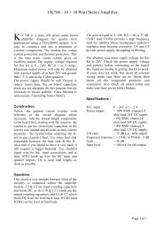
Project #222<br />
Transistor Amplifiers<br />
OBJECTIVE: To learn about the most important<br />
When you place one or more fingers across the two snaps marked X<br />
& Y you will notice the light comes on. The two transistors are being<br />
used to amplify the very tiny current going through your body to turn<br />
on the LED. Transistors are actually electrical current amplifiers. The<br />
PNP transistor has the arrow pointing into the transistor body. The<br />
NPN transistor has the arrow pointing out of the transistor body. The<br />
PNP amplifies the current from your fingers first, then the NPN<br />
amplifies it more to turn on the LED.<br />
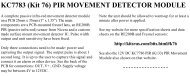
Project #223<br />
Pressure Meter<br />
OBJECTIVE: To show how electronic amplifiers can<br />
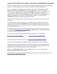
Project #224<br />
Resistance Meter<br />
OBJECTIVE: To show how electronic amplifiers can<br />
Use the circuit from Project 222 shown above.<br />
When you placed your fingers across the two snaps marked X & Y you<br />
noticed the LED came on in Project 222. Repeat this process, but this<br />
time press very lightly on the two snaps marked X and Y. Notice how<br />
the brightness of the LED is dependent on the amount of pressure you<br />
use. Pressing hard makes the LED bright while pressing very gently<br />
makes it dim or even flash. This is due to what technicians call contact<br />
resistance. Even switches made to turn your lights on and off have<br />
some resistance in them. When large currents flow this resistance, will<br />
drop the voltage and produce the undesirable side effect of heat.<br />
-39-<br />
Use the circuit from Project 222 shown above<br />
When you placed your fingers across the two snaps marked X & Y you<br />
noticed the LED came on in Project 222. In this project, you will place<br />
different resistors across R and Z and see how bright the LED glows.<br />
Do not snap them in; just press them up against the snaps labeled R<br />
and Z in the diagram above.<br />
First, place the 100kΩ resistor across the R & Z snaps and note the<br />
brightness of the LED. Next, press the 5.1kΩ resistor across R & Z.<br />
Notice how the LED gets brighter when the resistance is less. This is<br />
because the NPN amplifier gets more current at its input when the<br />
resistance is lower. The PNP amplifier is not used in this test.