F-3200 Series Inline Electromagnetic Flow Meter Manual - Onicon
F-3200 Series Inline Electromagnetic Flow Meter Manual - Onicon
F-3200 Series Inline Electromagnetic Flow Meter Manual - Onicon

You also want an ePaper? Increase the reach of your titles
YUMPU automatically turns print PDFs into web optimized ePapers that Google loves.
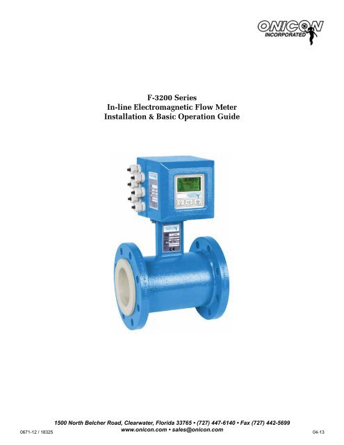
F-<strong>3200</strong> <strong>Series</strong><br />
In-line <strong>Electromagnetic</strong> <strong>Flow</strong> <strong>Meter</strong><br />
Installation & Basic Operation Guide<br />
1500 North Belcher Road, Clearwater, Florida 33765 • (727) 447-6140 • Fax (727) 442-5699<br />
0671-12 / 18325<br />
www.onicon.com • sales@onicon.com 04-13
1500 North Belcher Road, Clearwater, FL 33765 • Tel (727) 447-6140 • Fax (727) 442-5699 • sales@onicon.com<br />
F-<strong>3200</strong> <strong>Flow</strong> <strong>Meter</strong> <strong>Manual</strong> 04/13 - 0671-12 / 18325 Page 2
SAFETY INFORMATION<br />
This meter was calibrated at the factory before shipment. To ensure correct use of the meter, please<br />
read this manual thoroughly.<br />
Regarding this <strong>Manual</strong>:<br />
• This manual should be passed on to the end user.<br />
• Before use, read this manual thoroughly to comprehend its contents.<br />
• The contents of this manual may be changed without prior notice.<br />
• All rights reserved. No part of this manual may be reproduced in any form without<br />
ONICON’s written permission.<br />
• ONICON makes no warranty of any kind with regard to this material, including, but not<br />
limited to, implied warranties of merchantability and suitability for a particular purpose.<br />
• All reasonable effort has been made to ensure the accuracy of the contents of this manual.<br />
However, if any errors are found, please inform ONICON.<br />
• ONICON assumes no responsibilities for this product except as stated in the warranty.<br />
• If the customer or any third party is harmed by the use of this product, ONICON assumes<br />
no responsibility for any such harm owing to any defects in the product which were not<br />
predictable, or for any indirect damages.<br />
Safety Precautions:<br />
The following general safety precautions must be observed during all phases of installation,<br />
operation, service, and repair of this product. Failure to comply with these precautions or with<br />
specific WARNINGS given elsewhere in this manual violates safety standards of design,<br />
manufacture, and intended use of the product. ONICON Incorporated assumes no liability for the<br />
customer’s failure to comply with these requirements. If this product is used in a manner not<br />
specified in this manual, the protection provided by this product may be impaired.<br />
The following symbols are used in this manual:<br />
!<br />
WARNING<br />
Messages identified as “Warning” contain information regarding the personal safety of individuals<br />
involved in the installation, operation or service of this product.<br />
!<br />
CAUTION<br />
Messages identified as “Caution” contain information regarding potential damage to the product or<br />
other ancillary products.<br />
i<br />
IMPORTANT NOTE<br />
Messages identified as “Important Note” contain information critical to the proper operation of the<br />
product.<br />
1500 North Belcher Road, Clearwater, FL 33765 • Tel (727) 447-6140 • Fax (727) 442-5699 • sales@onicon.com<br />
F-<strong>3200</strong> <strong>Flow</strong> <strong>Meter</strong> <strong>Manual</strong> 04/13 - 0671-12 / 18325 Page 3
1500 North Belcher Road, Clearwater, FL 33765 • Tel (727) 447-6140 • Fax (727) 442-5699 • sales@onicon.com<br />
F-<strong>3200</strong> <strong>Flow</strong> <strong>Meter</strong> <strong>Manual</strong> 04/13 - 0671-12 / 18325 Page 4
TABLE OF CONTENTS<br />
1.0 INTRODUCTION ..................................................................................................7<br />
1.1 PURPOSE OF THIS GUIDE....................................................................... 7<br />
1.2 PRINCIPLE OF OPERATION..................................................................... 7<br />
1.3 TYPICAL FLOW METER INSTALLATION ...............................................7<br />
1.4 STANDARD FEATURES AND SPECIFICATIONS.................................... 8<br />
1.5 ADDITIONAL HARDWARE THAT MAY BE REQUIRED..........................9<br />
1.5.1 Grounding Rings...........................................................................9<br />
1.5.2 Gaskets........................................................................................10<br />
1.6 WORKING ENVIRONMENT ...................................................................10<br />
1.7 WARRANTY AND SERIAL NUMBER ...................................................10<br />
2.0 UNPACKING .....................................................................................................11<br />
2.1 CHECKING THAT YOU HAVE RECEIVED EVERYTHING.................... 11<br />
3.0 INSTALLATION.................................................................................................. 12<br />
3.1 SITE SELECTION .....................................................................................12<br />
3.1.1 General Guidelines.....................................................................13<br />
3.1.2 <strong>Flow</strong> Direction............................................................................13<br />
3.1.3 Remote Mount Transmitter........................................................13<br />
3.1.4 Minimum Straight Run Requirements.......................................14<br />
3.2 MECHANICAL INSTALLATION .............................................................15<br />
3.2.1 Standard Transmitter Dimensions.............................................15<br />
3.2.2 Sensor Body Dimensions & Weights..........................................16<br />
3.2.3 Installation Drawing for Conductive Pipe ................................19<br />
3.2.4 Installation Drawing for Non Conductive Pipe.........................21<br />
3.2.5 Installation Drawing for Threaded Connections...................... 21<br />
3.2.6 Installation Instructions............................................................ 22<br />
3.2.7 Torque Specifications ................................................................24<br />
3.2.8 Remote Mount Transmitter........................................................25<br />
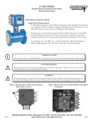
3.3 ELECTRICAL INSTALLATION ...............................................................26<br />
3.3.1 Input Power Requirements.........................................................26<br />
3.3.2 Analog and Pulse Output Signals..............................................26<br />
3.3.3 Power and Output Signal Wiring Instructions..........................27<br />
3.3.4 Earth Connections.......................................................................29<br />
3.3.5 Remote Mount Cable Wiring Instructions.................................30<br />
1500 North Belcher Road, Clearwater, FL 33765 • Tel (727) 447-6140 • Fax (727) 442-5699 • sales@onicon.com<br />
F-<strong>3200</strong> <strong>Flow</strong> <strong>Meter</strong> <strong>Manual</strong> 04/13 - 0671-12 / 18325 Page 5
TABLE OF CONTENTS (CONTINUED)<br />
4.0 F-<strong>3200</strong> START-UP AND COMMISSIONING .....................................................31<br />
4.1 DISPLAY AND KEYPAD OPERATION....................................................31<br />
4.2 ALARMS INTERPRETATION AND LED’S .............................................32<br />
4.3 START-UP AND COMMISSIONING........................................................32<br />
4.4 START-UP AND COMMISSIONING WORKSHEET................................33<br />
4.5 TROUBLESHOOTING GUIDE..................................................................33<br />
4.6 ALARMS INTERPRETATION AND LED’S..............................................34<br />
4.7 ALARM MESSAGES AND ACTION TO TAKE.......................................35<br />
APPENDIX<br />
A-1 FIELD REMOTE MOUNTING THE TRANSMITTER .......................................37<br />
A-2 CONDITIONS OF SALE.....................................................................................40<br />
1500 North Belcher Road, Clearwater, FL 33765 • Tel (727) 447-6140 • Fax (727) 442-5699 • sales@onicon.com<br />
F-<strong>3200</strong> <strong>Flow</strong> <strong>Meter</strong> <strong>Manual</strong> 04/13 - 0671-12 / 18325 Page 6
SECTION 1.0: INTRODUCTION<br />
1.1 PURPOSE OF THIS GUIDE<br />
The purpose of this guide is to provide installation and commissioning procedures and basic<br />
operating instructions for the F-<strong>3200</strong> In-line <strong>Electromagnetic</strong> <strong>Flow</strong> <strong>Meter</strong>.<br />
1.2 PRINICPLE OF OPERATION<br />
The operating principles of ONICON F-<strong>3200</strong> <strong>Inline</strong> <strong>Electromagnetic</strong> <strong>Flow</strong> <strong>Meter</strong>s are based on<br />
Faraday’s Law of <strong>Electromagnetic</strong> Induction. Faraday’s Law states that a voltage will be induced<br />
in a conductor (water or other conductive liquid) when it passes through a magnetic field<br />
(generated by the meter), and the induced voltage will be directly proportional to the velocity of<br />
the conductor. By placing electrodes on opposite sides of the flow tube, it is possible to accurately<br />
measure the induced voltage and determine the corresponding velocity of the flowing liquid.<br />
!<br />
WARNING<br />
Only qualified service personnel should attempt to install or service this product. Serious injury may<br />
result from the improper installation or use of this product.<br />
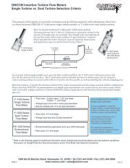
1.3 TYPICAL FLOW METER INSTALLATION<br />
ONICON’S F-<strong>3200</strong> In-line <strong>Electromagnetic</strong> <strong>Flow</strong> <strong>Meter</strong>s are suitable for volumetric flow<br />
measurement of electrically conductive liquids in a wide variety of applications including<br />
bi-directional applications.<br />
1500 North Belcher Road, Clearwater, FL 33765 • Tel (727) 447-6140 • Fax (727) 442-5699 • sales@onicon.com<br />
F-<strong>3200</strong> <strong>Flow</strong> <strong>Meter</strong> <strong>Manual</strong> 04/13 - 0671-12 / 18325 Page 7
1.4 STANDARD FEATURES AND SPECIFICATIONS<br />
• A built-in user interface & graphic display<br />
• A single 4 – 20mA output for flow rate<br />
• Two programmable open collector pulse outputs. Outputs may be programmed to provide:<br />
* an indication of flow direction<br />
* a scaled pulse for totalizing flow<br />
* a high resolution frequency output to drive peripheral devices<br />
* an indication of an alarm condition<br />
• Empty pipe detector<br />
• Internal self-diagnostic functions & fault alarms<br />
CALIBRATION<br />
<strong>Flow</strong> meters are wet calibrated in a flow laboratory<br />
against standards that are directly traceable to<br />
government standards. A certificate of calibration<br />
accompanies every meter.<br />
ACCURACY<br />
Accurate to within:<br />
± 0.2% of reading from 1.6 to 33 ft/s<br />
± 0.0033 ft/s at flows less than 1.6 ft/s<br />
PROGRAMMING<br />
Factory programmed for specific application<br />
MEMORY<br />
Nonvolatile memory retains all program parameters<br />
and totalized values in the event of power loss.<br />
DISPLAY<br />
Alphanumeric LCD displays total flow, flow rate,<br />
flow direction & alarm conditions<br />
OUTPUT SIGNALS<br />
Isolated 4 – 20mA analog output for flow rate<br />
2 isolated programmable opto-coupled open<br />
collector digital/pulse outputs<br />
(Configurable for frequency, pulse, alarm or<br />
directional flow)<br />
40VDC, 100mA and 1250Hz maximum<br />
(Optional) Redundant output option with second<br />
isolated analog output for flow rate and 2 additional<br />
isolated programmable opto-coupled open collector<br />
digital/pulse outputs<br />
(Pulse outputs configurable for frequency, pulse,<br />
alarm or directional flow)<br />
40VDC, 100mA and 1250Hz maximum<br />
TEMPERATURE RANGE<br />
Liquid temperature range:<br />
Polypropylene liner: 32° to 140°F<br />
Ebonite liner: 23° to 175°F<br />
PTFE liner: -4° to 212° F (266° F with remote<br />
electronics without pre-amplifier option)<br />
Ambient temperature range: -4° to 140°F<br />
FLUID CONDUCTIVITY<br />
5 µS/cm minimum<br />
MAINTENANCE<br />
Periodically inspect the power supply cables,<br />
cable glands and the enclosure for signs of<br />
damage. Inspect installation and mounting hardware<br />
for loose connections.<br />
MECHANICAL<br />
Electronics Enclosure:<br />
Standard: Painted Aluminum NEMA 6<br />
(Optional) Remote mount w/o pre-amplifier,<br />
maximum distance from sensor - up to 325 ft @<br />
conductivities ≥ 200µS/cm<br />
Remote mount transmitter with pre-amplifier in<br />
sensor body (maximum distance from sensor<br />
body, 1640ft).<br />
Outer Body Material:<br />
Standard: Carbon Steel, Painted<br />
Optional: 316 Stainless Steel<br />
<strong>Flow</strong> Tube (Internal):<br />
304 Stainless Steel<br />
Connection Type:<br />
Standard: ANSI 150 Class Flange<br />
Optional: ANSI 300 Class Flange<br />
Optional: Wafer<br />
Optional: Threaded Process Connection<br />
ELECTRICAL<br />
This equipment is intended for INSTALLATION<br />
CATEGORY (OVERVOLTAGE CATEGORY) II<br />
applications.<br />
Input Power - Factory Selectable:<br />
Standard - 100 - 240 VAC, 45 - 66 Hz, 12 VA typical<br />
Optional - 18 - 45 VDC, 10 W typical<br />
OR 18 - 45 VAC, 45 - 66 Hz, 12 VA typical<br />
Overcurrent Protective Device Ratings:<br />
Supply mains overcurrent protective devices with<br />
the following ratings:<br />
• 120VAC 50/60 Hz – 15 A<br />
• 230VAC 50 Hz – 6 A<br />
Wiring:<br />
<strong>Flow</strong> signals - Use 18-22 AWG shielded cable<br />
Standard input power - Use a three wire service<br />
with one wire a protective earth ground. The<br />
installation must comply with all local, state and<br />
federal building codes.<br />
Optional input power - Use PVC jacketed copper<br />
cable with a wire gauge suitable for the length of<br />
run and required maximum current carrying<br />
capacity. The installation must comply with all<br />
local, state and federal building codes.<br />
Note: Specifications are subject to change without notice.<br />
1500 North Belcher Road, Clearwater, FL 33765 • Tel (727) 447-6140 • Fax (727) 442-5699 • sales@onicon.com<br />
F-<strong>3200</strong> <strong>Flow</strong> <strong>Meter</strong> <strong>Manual</strong> 04/13 - 0671-12 / 18325 Page 8
1.5 ADDITIONAL HARDWARE THAT MAY BE REQUIRED<br />
1.5.1 Grounding Rings<br />
Grounding rings may be required whenever meters are installed in non-metallic or lined<br />
pipes. Grounding rings placed before and after the meter eliminates electrical noise that<br />
will interfere with the proper operation of the meter. ONICON provides grounding rings<br />
as an optional accessory. Grounding ring dimensional information and part numbers are<br />
listed below. For proper operation, grounding rings are required before and after the meter.<br />
5/8<br />
3/8<br />
D<br />
1/4<br />
C<br />
Bore<br />
1/8”<br />
A<br />
Grounding Ring Dimensions & ONICON Part Numbers<br />
Nominal<br />
Size<br />
Bore A C D T 316 SS Part<br />
#<br />
1” 1 - 1/16 2 - 5/8 4 - 9/16 1 - 15/16 1/8 15212<br />
1.5” 1 – 9/16 3 – 3/8 5 - 5/16 1 - 15/16 1/8 15213<br />
2” 2 – 1/16 4 – 1/8 6 - 1/16 1 - 15/16 1/8 15214<br />
3” 3 – 1/16 5 – 3/8 7 - 5/16 1 - 15/16 1/8 15215<br />
4” 4 – 1/16 6 – 7/8 8 - 13/16 1 - 15/16 1/8 15216<br />
6” 6 8 – 3/4 10 - 11/16 1 - 15/16 1/8 15217<br />
8” 8 11 12 - 15/16 1 - 15/16 1/8 15218<br />
10” 9 – 1/2 13 – 3/8 15 - 5/8 2 - 1/4 1/8 15219<br />
12” 11 – 9/16 16 – 1/8 18 - 9/16 2 - 7/16 1/8 15220<br />
14” 13 – 1/2 17 – 3/4 20 - 3/8 2 - 5/8 1/8 15221<br />
16” 15 – 1/4 20 – 1/4 22 - 7/8 2 - 5/8 1/8 15222<br />
18” 17 – 3/8 21 – 5/8 24 - 1/4 2 - 5/8 1/8 15223<br />
20” 19 23 - 7/8 26 - 11/16 2 - 13/16 1/8 15224<br />
24” 23 28 – 1/4 31 - 1/8 2 - 7/8 1/8 15225<br />
30” 29 34 – 3/4 38 3 - 1/2 1/8 15226<br />
36” 35 41 – 1/4 45 - 1/4 4 1/8 15227<br />
42” 41 48 52 - 1/2 4 - 1/2 1/8 15228<br />
1500 North Belcher Road, Clearwater, FL 33765 • Tel (727) 447-6140 • Fax (727) 442-5699 • sales@onicon.com<br />
F-<strong>3200</strong> <strong>Flow</strong> <strong>Meter</strong> <strong>Manual</strong> 04/13 - 0671-12 / 18325 Page 9
1.5.2 Gaskets<br />
Gaskets are required for sensor bodies with ebonite and polypropylene liners and are<br />
strongly recommended for meters with PTFE liners. Gasket dimensions must comply with<br />
ASME B16.5 flange standards. ONICON is not a gasket manufacturer and does not supply<br />
gaskets for this product.<br />
The following general suggestions are provided to assist the installer in choosing the<br />
proper gasket material. In all cases, the responsibility of selecting the appropriate material<br />
rests with the installer.<br />
Gaskets are used to create a seal between the flow meter liner surface and the surface<br />
of the mating flange. The proper choice of gasket material will allow for a leak free<br />
connection at the time of installation and maintain that seal over time. How well the<br />
gasket works depends on a number of factors. Each of these should be considered when<br />
choosing a gasket material.<br />
• Is it chemically compatible with the fluid?<br />
• Will it withstand the expected minimum and maximum operating temperatures?<br />
• Does it provide enough resiliency and creep resistance to maintain loading over time?<br />
• Will it deform enough to create a seal by filling imperfections in the sealing surfaces?<br />
• Is it thick enough to take up variations in flatness of the surface?<br />
In many cases a simple 1/8” red rubber gasket with a Shore A hardness (Durometer) of<br />
60 – 80 will suffice. Your local gasket supplier should be able to guide you in selecting the<br />
best material for your application.<br />
1.6 WORKING ENVIRONMENT<br />
The F-<strong>3200</strong> was designed for installation and use in typical industrial environments that are free<br />
of corrosive liquids and fumes, direct liquid exposure, direct sunlight, temperature extremes and<br />
vibrations.<br />
The operating ambient air temperature range is -4° F to 140° F.<br />
The electrical power should be relatively clean, free of high frequency noise, large voltage<br />
transients, and protected from power surges and brown outs.<br />
1.7 WARRANTY & SERIAL NUMBER<br />
Warranty<br />
ONICON’s complete warranty is included the “Conditions of Sale”. ONICON provides a<br />
two-year warranty.<br />
Serial Number<br />
The F-<strong>3200</strong> has 2 separate serial numbers. The transmitter serial number is located on<br />
the identification plate located on the electronics enclosure. The sensor serial number is<br />
located on the identification plate located on the sensor body.<br />
1500 North Belcher Road, Clearwater, FL 33765 • Tel (727) 447-6140 • Fax (727) 442-5699 • sales@onicon.com<br />
F-<strong>3200</strong> <strong>Flow</strong> <strong>Meter</strong> <strong>Manual</strong> 04/13 - 0671-12 / 18325 Page 10
SECTION 2.0: UNPACKING<br />
The F-<strong>3200</strong> is generally shipped in one package unless optional hardware or equipment is ordered.<br />
Notify the freight carrier (all products are shipped insured) and ONICON if any items are damaged in<br />
transit.<br />
2.1 CHECKING THAT YOU HAVE RECEIVED EVERYTHING<br />
• Standard Documentation<br />
Enclosed with each F-<strong>3200</strong> is a comprehensive documentation package that includes<br />
the following items:<br />
The F-<strong>3200</strong> Installation and Operation Guide<br />
Certifiat of Calibration<br />
Please notify ONICON if any of these items are missing.<br />
F-<strong>3200</strong> <strong>Series</strong><br />
In-line <strong>Electromagnetic</strong> <strong>Flow</strong> <strong>Meter</strong><br />
Installation & Basic Operation Guide<br />
1500 North Belcher Road, Clearwater, Florida 33765 • (727) 447-6140 • Fax (727) 442-5699<br />
0671-2<br />
www.onicon.com • sales@onicon.com 03-11<br />
FLOW METER<br />
CERTIFICATE OF CALIBRATION<br />
CALIBRATION & CONFIGURATION DATA for F-3000 SERIES MAGNETIC FLOW METERS<br />
METER DATA<br />
CALIBRATION of PRIMARY FLOW ELEMENT<br />
<strong>Meter</strong> Tag: CT-WH Ka factor:<br />
-1.0951<br />
Model:<br />
F-3103-111<br />
Medium:<br />
Water<br />
Serial Number: 220177<br />
Component S/N's: 04N1420 38M6901<br />
Primary Calibration Date: 4/12/2011<br />
<strong>Meter</strong> Size: 3"<br />
Max. Operating Pressure:<br />
225 psi<br />
Max. Operating Temperature: 212 °F<br />
Connections: ANSI 150# Class Flanges<br />
Peripheral device serial number 220177<br />
This meter was manufactured for ONICON Incorporated.<br />
The original manufacturer certifies that this flow meter was<br />
calibrated against standards that are traceable to<br />
SIT, Italy.<br />
FACTORY PROGRAMMED OUTPUT SIGNALS<br />
(Performed at ONICON Factory; can be reprogrammed in the field)<br />
Analog <strong>Flow</strong> Range: 4-20 mA = 0 to<br />
230 Gal/Min<br />
Full Scale Frequency Output: 200.00 Hz<br />
Scaled Pulse Output: 1 100 Gallons<br />
pulse =<br />
Programmed By:<br />
GL<br />
Date: 5/25/2011<br />
1500 N Belcher Road, Clearwater, Florida 33765 Tel (727)447-6140 Fax (727)442-5699<br />
1500 North Belcher Road, Clearwater, FL 33765 • Tel (727) 447-6140 • Fax (727) 442-5699 • sales@onicon.com<br />
F-<strong>3200</strong> <strong>Flow</strong> <strong>Meter</strong> <strong>Manual</strong> 04/13 - 0671-12 / 18325 Page 11
• Integral Mount Transmitter<br />
F-<strong>3200</strong> in-line magnetic flow meters with integrally mounted transmitters are shipped fully<br />
assembled. Remove the meter from the shipping carton and inspect it for physical damage.<br />
• Remote Mount Transmitter<br />
F-<strong>3200</strong> in-line magnetic flow meters ordered with the remote transmitter mounting option will<br />
be provided in one carton that contains the flow sensor body, the transmitter with mounting<br />
hardware and the necessary cable to connect the two together. Remove each and inspect it for<br />
physical damage.<br />
i<br />
IMPORTANT NOTE<br />
F-<strong>3200</strong> transmitters and sensor bodies are two parts of one uniquely calibrated system and must be<br />
installed together. Mixing components from other systems will result in significant calibration errors.<br />
• Grounding Rings<br />
Grounding rings are optional accessories that may be required for proper installation.<br />
Grounding rings may be shipped in a separate carton. Remove each and inspect it for<br />
physical damage.<br />
SECTION 3.0: INSTALLATION<br />
The F-<strong>3200</strong> <strong>Inline</strong> <strong>Electromagnetic</strong> <strong>Flow</strong> <strong>Meter</strong> should be installed by experienced plumbers,<br />
electricians and others with related knowledge and experience in the heating, cooling, and fluid<br />
metering fields. ONICON will be happy to assist with technical recommendations and to provide<br />
guidance by telephone and/or email. On-site field engineering, installation and service are also<br />
available at an additional cost.<br />
The installer should use good trade practices and must adhere to all state and local building or other<br />
applicable codes.<br />
3.1 SITE SELECTION<br />
Careful attention during the site selection process will help the installers with the initial<br />
installation, reduce start-up problems, and make future maintenance easier. For example, do not<br />
install the flow meter where it will be difficult for personnel to perform periodic maintenance.<br />
When selecting a site for mounting, consider the criteria under Section 1.6, WORKING<br />
ENVIRONMENT, as well as the following:<br />
i<br />
IMPORTANT NOTE<br />
Proper site selection is critical to the performance of this flow meter. The flow meter must be<br />
properly located within the piping system in order to ensure an accurate flow measurement.<br />
1500 North Belcher Road, Clearwater, FL 33765 • Tel (727) 447-6140 • Fax (727) 442-5699 • sales@onicon.com<br />
F-<strong>3200</strong> <strong>Flow</strong> <strong>Meter</strong> <strong>Manual</strong> 04/13 - 0671-12 / 18325 Page 12
3.1.1 General Guidelines<br />
When properly installed, the flow meter will only measure flow associated with that<br />
portion of the piping system for which the flow measurement is being made. Choose the<br />
location with the longest straight unobstructed run of pipe, keeping in mind that in some<br />
applications it may be possible to locate the meter in either the supply or return pipe.<br />
3.1.2 <strong>Flow</strong> Direction<br />
F-<strong>3200</strong> flow meters are inherently bi-directional and changes in flow direction are<br />
indicated by a change in polarity of the sensing signal. In order for the meter to display<br />
the correct polarity, it is necessary to orient the meter relative to flow direction during<br />
the installation process. The sign of the flow rate is positive when the flow direction is<br />
from – to + as printed on the tag plate as shown below. Prior to installation, determine the<br />
direction of flow in the piping system and orient the meter accordingly.<br />
-<br />
FLOW DIRECTION+<br />
i<br />
IMPORTANT NOTE<br />
<strong>Flow</strong> direction is indicated by polarity symbols (+/-) and flow totals are accumulated separately<br />
based on direction. The polarity of the flow indication may be reversed by reversing the polarity of<br />
the Ka coefficient.<br />
3.1.3 Remote Mounted Transmitter<br />
Find an easily accessible location where wire connections can be made and meter readings<br />
can be taken from floor level. Mount the transmitter on a vibration free surface. Avoid<br />
locations that contain electric motors or other strong sources of electrical interference.<br />
i<br />
IMPORTANT NOTE<br />
The standard F-<strong>3200</strong> remote mounted transmitter option is provided without a pre-amplifier. As<br />
a result, the maximum distance it can be located away from the sensor body is limited to 65ft. A<br />
sensor body with a pre-amplifier is also available. With this option the remote transmitter may be<br />
located up to 1640 ft away from the sensor body. Contact ONICON if you need to locate the remote<br />
transmitter more than 65ft from the sensor body.<br />
1500 North Belcher Road, Clearwater, FL 33765 • Tel (727) 447-6140 • Fax (727) 442-5699 • sales@onicon.com<br />
F-<strong>3200</strong> <strong>Flow</strong> <strong>Meter</strong> <strong>Manual</strong> 04/13 - 0671-12 / 18325 Page 13
3.1.4 Pipe System Requirements<br />
The straight run requirements presented below represent the minimum requirements<br />
for accurate flow measurement. For optimum performance, provide as much additional<br />
straight run as possible.<br />
i<br />
IMPORTANT NOTE<br />
For proper operation, install the flow meter in a straight run of pipe free of bends, tees, valves,<br />
transitions and obstructions for a distance of at least 3 diameters upstream and 2 diameters<br />
downstream.<br />
Recommended Installation<br />
Avoid these installations<br />
Place pipe at least 3 pipe<br />
diameters downstream and<br />
2 pipe diameters upstream<br />
from bends and obstrutions.<br />
3 DIA 2 DIA<br />
3 DIA 2 DIA<br />
Avoid downward flow<br />
which can lead to partially<br />
filled pipes.<br />
3 DIA 2 DIA<br />
Electrode location<br />
<br />
<br />
The electrodes should<br />
be located in the<br />
horizontal axis (3 o’clock<br />
and 9 o’clock) in order to<br />
prevent sediment from<br />
settling on them.<br />
Electrode Electrode location Location<br />
1500 North Belcher Road, Clearwater, FL 33765 • Tel (727) 447-6140 • Fax (727) 442-5699 • sales@onicon.com<br />
F-<strong>3200</strong> <strong>Flow</strong> <strong>Meter</strong> <strong>Manual</strong> 04/13 - 0671-12 / 18325 Page 14
3.2 MECHANICAL INSTALLATION<br />
i<br />
IMPORTANT NOTE<br />
F-<strong>3200</strong> transmitters and sensor bodies are two parts of one uniquely calibrated system and must<br />
be installed together. Mixing components from other systems will result in significant calibration<br />
errors.<br />
3.2.1 Standard Transmitter Dimensions<br />
1500 North Belcher Road, Clearwater, FL 33765 • Tel (727) 447-6140 • Fax (727) 442-5699 • sales@onicon.com<br />
F-<strong>3200</strong> <strong>Flow</strong> <strong>Meter</strong> <strong>Manual</strong> 04/13 - 0671-12 / 18325 Page 15
3.2.2 Sensor Dimensions & Weights<br />
Ansi Class 150 Flanged Sensor Overall Dimension<br />
H<br />
D<br />
L<br />
Shown with 4-bolt pattern<br />
Sensor Size<br />
Nominal Diameter 1” 1.25” 1.5” 2” 2.5” 3” 4” 5” 6” 8” 10” 12”<br />
Lenght (L above) 7.87 7.87 7.87 7.87 7.87 7.87 9.84 9.84 11.81 13.78 17.72 19.68<br />
Height (H above) 7.13 7.55 8.15 8.74 9.64 10.20 11.34 12.40 13.43 15.79 18.15 20.75<br />
Flange Dia (D above) 4.24 46.4 5.00 5.98 7.00 7.52 9.02 10.00 10.98 13.50 15.98 19.02<br />
Weight in lbs 6.6 9.7 11 15.4 21.5 26.4 32.0 35.2 55 75 138 159<br />
Sensor Size<br />
Nominal Diameter 14” 16” 18” 20” 24” 26” 30” 34” 36” 42” 48”<br />
Length (L above) 21.65 23.62 23.62 23.62 23.62 25.59 29.53 33.46 35.43 39.37 47.24<br />
Height (H above) 22.91 25.16 27.08 29.57 34.09 36.26 40.63 45.24 47.48 54.37 58.66<br />
Flange Dia (D above) 20.98 23.50 25.00 27.52 32.01 34.25 38.74 43.74 45.98 52.99 57.28<br />
Weight in lbs 238 341 407 462 664 770 911 1210 1386 1716 1948<br />
1500 North Belcher Road, Clearwater, FL 33765 • Tel (727) 447-6140 • Fax (727) 442-5699 • sales@onicon.com<br />
F-<strong>3200</strong> <strong>Flow</strong> <strong>Meter</strong> <strong>Manual</strong> 04/13 - 0671-12 / 18325 Page 16
Wafer Style Sensor Overall Dimensions<br />
G<br />
0.95"<br />
H<br />
D<br />
L<br />
I.D.<br />
Sensor Size<br />
Nominal Diameter 1” 1.25” 1.5” 2” 2.5” 3” 4” 5” 6” 8” 10” 12” 14” 16”<br />
L 3.94 3.94 3.94 3.94 5.90 5.90 5.90 7.09 7.09 7.87 9.84 11.81 13.78 15.75<br />
H 5.79 6.02 6.34 6.97 7.83 8.23 9.25 10.35 11.46 14.25 16.42 18.39 20.75 22.80<br />
D 2.20 2.44 2.76 3.39 4.25 4.65 5.67 6.77 7.87 10.67 12.83 14.80 17.17 19.21<br />
G - - - - - - - - - 5.67 7.64 9.60 11.57 13.54<br />
Net Weight in lbs 2.6 3.5 4.0 4.4 7.9 8.4 11 17.2 18 40 53 59 70 86<br />
Threaded Version<br />
H<br />
Polypropylene Stainless Steele<br />
Weight 4.85 lbs 4.85 lbs<br />
L 5.5” 4.72”<br />
H 7.4” 6.69”<br />
W 3.8” 3.07”<br />
L<br />
W<br />
1500 North Belcher Road, Clearwater, FL 33765 • Tel (727) 447-6140 • Fax (727) 442-5699 • sales@onicon.com<br />
F-<strong>3200</strong> <strong>Flow</strong> <strong>Meter</strong> <strong>Manual</strong> 04/13 - 0671-12 / 18325 Page 17
Recommended method for lifting all sensors with eyebolts<br />
The eyebolts are<br />
designed to hold only<br />
the weight of the meter<br />
!<br />
WARNING<br />
Eyebolts are provided to assist in the safe installation of meters with a nominal diameter greater<br />
than 6 inches. The eyebolts are only designed to hold the weight of the meter. Do not attempt to<br />
place an additional load on the eyebolts during installation.<br />
1500 North Belcher Road, Clearwater, FL 33765 • Tel (727) 447-6140 • Fax (727) 442-5699 • sales@onicon.com<br />
F-<strong>3200</strong> <strong>Flow</strong> <strong>Meter</strong> <strong>Manual</strong> 04/13 - 0671-12 / 18325 Page 18
F-3000 3.2.3 Installation <strong>Series</strong> Drawings Mating for Conductive Flange Pipe Grounding Kit Instructions<br />
Note 2.<br />
INSTALLATION IN STEEL (CONDUCTIVE) PIPE<br />
<strong>Flow</strong> direction<br />
Note 1. Note 1.<br />
Note 3.<br />
Note 1.<br />
Using a # 21 (0.159") drill bit, drill<br />
1a<br />
2 " deep hole in edge of each mating flange. Tap each hole<br />
hole using a 10-32 tap. Secure the ring connectors (provided) and grounding wires to the flange<br />
using a 10-32 tap. Secure the ring connectors (provided) and wires to the flange us<br />
using the green grounding screws (provided).<br />
the green grounding screws (provided).<br />
(Alternate (Alternate method method: : Weld Weld 10-32 studs (not provided) to to the the flange flange faces faces and attach and ring attach ring<br />
connectors with 10-32 nuts (not provided).<br />
Note 1. Using a #21 (0.159”) drill bit, drill a ½” deep hole in edge of each mating flange. Tap each<br />
connectors with 10-32 nuts (not provided).<br />
Note 2.<br />
Provide a ground connection at the input power terminals inside the transmitter enclosure.<br />
Note 2. Provide a ground connection at the input power terminals inside the transmitter enclosure.<br />
Note 3. Provide a quality earth ground connection to the meter.<br />
Note 3.<br />
From best to worst, grounding options include:<br />
Provide a quality 1. Earth earth grounding ground rod driven connection into the to soil. the meter.<br />
From best to worst, grounding options include:<br />
1. Earth grounding 3. Earth wire rod connection driven into inside the an soil. electrical outlet mear the meter.<br />
2. Earth wire connected directly to the building electrical service panel.<br />
3. Earth wire connection inside an electrical outlet near the meter.<br />
CAUTION<br />
!<br />
2. Earth wire connected directly to the building electrical service panel.<br />
The earth connections must be made as shown. Failure to do so will result in erratic operation of<br />
the meter.<br />
1500 North Belcher Road, Clearwater, FL 33765 • Tel (727) 447-6140 • Fax (727) 442-5699 • sales@onicon.com<br />
F-<strong>3200</strong> <strong>Flow</strong> <strong>Meter</strong> <strong>Manual</strong> 04/13 - 0671-12 / 18325 Page 19
(Wafer Style <strong>Meter</strong>)<br />
Note 3.<br />
INSTALLATION IN CONDUCTIVE PIPE<br />
Note 2.<br />
<strong>Flow</strong> direction<br />
Note 1.<br />
Note 1.<br />
Note 4.<br />
Note 1.<br />
Using a # 21 (0.159") drill bit, drill<br />
1a<br />
2 " deep hole in edge of each mating flange. Tap each<br />
hole using a 10-32 tap. Secure the ring connectors (provided) and grounding wires to the<br />
flange using the green grounding screws (provided).<br />
(Alternate method : Weld 10-32 studs (not provided) to the flange faces and attach ring<br />
connectors with 10-32 nuts (not provided).<br />
Note 1. Using a #21 (0.159”) drill bit, drill a ½” deep hole in edge of each mating flange. Tap each<br />
hole using a 10-32 tap. Secure the ring connectors (provided) and grounding wires to the flange<br />
using the green grounding screws (provided).<br />
(Alternate method: Weld 10-32 studs (not provided) to the flange faces and attach ring<br />
connectors with 10-32 nuts (not provided).<br />
Note 2. For meters provided with a grounding electrode connect grounding wire to terminal on the<br />
Note 2.<br />
meter neck as shown.<br />
For meters provided with a grounding electrode connect grounding wire to terminal on th<br />
meter neck as shown.<br />
Note 3. Provide a ground connection at the input power terminals inside the transmitter enclosure.<br />
Note<br />
Note<br />
4. From<br />
3.<br />
best to worst, grounding options include:<br />
1. Earth grounding rod driven into the soil.<br />
2. Earth wire connected directly to the building electrical service panel.<br />
Note 4. 3. Earth wire connection inside an electrical outlet near the meter.<br />
!<br />
Provide a ground connection at the input power terminals inside the transmitter enclosur<br />
From best to worst, grounding options include:<br />
1. Earth grounding rod driven into the soil.<br />
2. Earth wire connected directly to the building electrical service panel.<br />
CAUTION<br />
3. Earth wire connection inside an electrical outlet near the meter.<br />
The earth connections must be made as shown. Failure to do so will result in erratic operation of<br />
the meter.<br />
1500 North Belcher Road, Clearwater, FL 33765 • Tel (727) 447-6140 • Fax (727) 442-5699 • sales@onicon.com<br />
F-<strong>3200</strong> <strong>Flow</strong> <strong>Meter</strong> <strong>Manual</strong> 04/13 - 0671-12 / 18325 Page 20
3.2.4 Installation Drawing for Non-Conductive Pipe<br />
INSTALLATION IN NON CONDUCTIVE PIPE<br />
GASKETS<br />
flow direction<br />
GROUNDING RING<br />
3.2.5 Installation Drawing for Threaded Connections<br />
THREADED<br />
PROCESSED<br />
CONNECTION<br />
FLOW DIRECTION<br />
3 DIA<br />
MINIMUM UPSTREAM<br />
STRAIGHT PIPE RUN<br />
2 DIA<br />
MINIMUM<br />
DOWNSTREAM<br />
STRAIGHT PIPE RUN<br />
!<br />
CAUTION<br />
The earth connections must be made as shown. Failure to do so will result in erratic operation of the<br />
meter.<br />
1500 North Belcher Road, Clearwater, FL 33765 • Tel (727) 447-6140 • Fax (727) 442-5699 • sales@onicon.com<br />
F-<strong>3200</strong> <strong>Flow</strong> <strong>Meter</strong> <strong>Manual</strong> 04/13 - 0671-12 / 18325 Page 21
3.2.6 Installation Instructions<br />
!<br />
WARNING<br />
Installation of this product should only be attempted by qualified tradespersons and must comply<br />
with all local, state and federal building codes.<br />
1. Thoroughly clean all flange surfaces removing all traces of any old gasket material or<br />
any adhesive residue.<br />
2. Inspect all flange surfaces for warping, pitting or other surface imperfections that may<br />
prevent a good seal.<br />
3. Use new bolts, nuts and hardened washers. ONICON recommends the use of B7 nuts,<br />
bolts and washers. Prior to installation, lubricate the bolt threads, nuts, washer faces<br />
and the underside of the bolt head with lubricant (Fel Pro C5A or equivalent). This<br />
lubricant is necessary to ensure uniform stress distribution on the sealing surface. Use<br />
care not to get any lubricant on the liner or gasket material.<br />
4. Center the new gasket on the liner surface. Do not allow the gasket to protrude into the<br />
flow stream.<br />
5. Use the torque specifications shown below to determine the recommended final bolt<br />
torque requirements.<br />
6. Using a torque wrench, tighten the bolts in at least three stages (30%, 60% & 100%)<br />
using a repeating pattern sequence shown in the diagrams below.<br />
ANSI Class 150 Flange Bolt Tightening Sequence<br />
Liner material.<br />
1500 North Belcher Road, Clearwater, FL 33765 • Tel (727) 447-6140 • Fax (727) 442-5699 • sales@onicon.com<br />
F-<strong>3200</strong> <strong>Flow</strong> <strong>Meter</strong> <strong>Manual</strong> 04/13 - 0671-12 / 18325 Page 22
ANSI Class 150 Flange Bolt Tightening Sequence<br />
1500 North Belcher Road, Clearwater, FL 33765 • Tel (727) 447-6140 • Fax (727) 442-5699 • sales@onicon.com<br />
F-<strong>3200</strong> <strong>Flow</strong> <strong>Meter</strong> <strong>Manual</strong> 04/13 - 0671-12 / 18325 Page 23
3.2.7 Torque Specifications<br />
Tighten uniformly in a diagonal sequence as per the table below. Contact ONICON for<br />
torque specifications for meters with a nominal diameter larger than 24 inches.<br />
Torque Specifications in ft-lb<br />
Operating Pressure<br />
PSI 140 260 350 600 1000<br />
Dia. PTFE EBON PTFE EBON PP PTFE EBON PTFE EBON EBON<br />
1” 19 14 19 19 29<br />
1.25” 32 21 32 32 40<br />
1.5” 40 27 40 40 54<br />
2” 51 39 51 51 60<br />
2.5” 67 56 34 34 63<br />
3” 40 31 40 40 46<br />
4” 44 42 62 62 65<br />
5” 57 53 83 83 110<br />
6” 80 79 100 100 161<br />
8” 110 91 73 61 99 83 132 110 172<br />
10” 91 76 104 87 151 126 197 165 237<br />
12” 105 88 130 108 149 124 205 172 234<br />
14” 127 106 152 127 239 200 312 260 355<br />
16” 161 134 208 174 315 262 457 381 460<br />
18” 144 119 208 173<br />
20” 166 138 282 235<br />
24” 239 199 419 350<br />
1500 North Belcher Road, Clearwater, FL 33765 • Tel (727) 447-6140 • Fax (727) 442-5699 • sales@onicon.com<br />
F-<strong>3200</strong> <strong>Flow</strong> <strong>Meter</strong> <strong>Manual</strong> 04/13 - 0671-12 / 18325 Page 24
3.2.8 Remote Mount Transmitter<br />
Remote mount transmitters are provided with a single “L” bracket with 2 - ¼” mounting<br />
holes. The bracket is secured to the transmitter by means of a large bolt with a knurled<br />
knob for a head. To mount the bracket, first separate it from the transmitter housing and<br />
attach it to the wall or other vertical surface. Cable from the sensor body is attached to the<br />
transmitter using the center strain relief.<br />
Mounting Bracket<br />
Cable is supplied<br />
already attached to<br />
the sensor body.<br />
Cable wires are<br />
labeled with numbers<br />
which correspond to<br />
connection terminals<br />
on the transmitter.<br />
!<br />
CAUTION<br />
DO NOT drill holes in the main unit. Use only the openings that are provided. DO NOT cut the<br />
remote cable. Coil excess cable at one end.<br />
2.5”<br />
1”<br />
0.25” DIA<br />
Insert<br />
1500 North Belcher Road, Clearwater, FL 33765 • Tel (727) 447-6140 • Fax (727) 442-5699 • sales@onicon.com<br />
F-<strong>3200</strong> <strong>Flow</strong> <strong>Meter</strong> <strong>Manual</strong> 04/13 - 0671-12 / 18325 Page 25
3.3 ELECTRICAL INSTALLATION<br />
3.3.1 Input Power Requirements<br />
F-3000 <strong>Electromagnetic</strong> <strong>Flow</strong> <strong>Meter</strong>s equipped with advanced transmitters are available with two<br />
different options for input power. This is not a user selectable function and must be configured at<br />
the factory.<br />
Special care is required to ensure that the F-<strong>3200</strong> is properly connected to earth through an<br />
earth wire. This connection is required to prevent random electrical noise from interfering with<br />
the operation of the meter. (See section 3.3.3 for details.)<br />
* Low Voltage: 18 – 45 VDC, 18 – 45 VAC 45/66 Hz, 300 mA maximum<br />
* High Voltage (Mains): 100 – 240 VAC 45/66 Hz, 35 mA maximum<br />
i<br />
IMPORTANT NOTE<br />
This option is not field selectable. Contact the factory if you need to change the input voltage rating.<br />
!<br />
CAUTION/WARNING<br />
This product must be connected to earth ground for proper operation. Failure to do so will result in<br />
erratic operation and an increased risk of injury.<br />
!<br />
WARNING<br />
All mains voltage connections must be made through pre-drilled conduit/strain relief opening<br />
located at the bottom of the enclosure. Failure to do so will result in an increased risk of injury.<br />
3.3.2 Analog and Pulse Output Signals<br />
The primary output signals from ONICON F-<strong>3200</strong> series electromagnetic flow meters include<br />
a single analog output for flow rate and two programmable pulse outputs for use as frequency,<br />
scaled pulse, alarm and flow direction signals. The three outputs have 500 VDC of electrical<br />
isolation between the flow sensing circuitry, the microprocessor circuitry, and the pulse and<br />
analog output circuitry. In addition, the output circuits operate from dedicated power supply<br />
circuitry that is isolated from all other internal power sources and from earth.<br />
Redundant Output Option<br />
The redundant output option for the F-<strong>3200</strong> series electromagnetic flow meter provides complete<br />
signal redundancy for the three primary output signals from the meter. It provides an additional<br />
4-20mA output and two additional programmable pulse outputs and is designed with the<br />
same 500 VDC electrical isolation as the primary outputs. The redundant output transmitter is<br />
controlled directly from the microprocessor and is completely independent of the primary output<br />
circuitry.<br />
1500 North Belcher Road, Clearwater, FL 33765 • Tel (727) 447-6140 • Fax (727) 442-5699 • sales@onicon.com<br />
F-<strong>3200</strong> <strong>Flow</strong> <strong>Meter</strong> <strong>Manual</strong> 04/13 - 0671-12 / 18325 Page 26
3.3.3 Power and Output Signal Wiring Instructions<br />
Factory Default Output Configurations<br />
ONICON pre-programs the analog and pulse outputs based on application specific data<br />
provided at the time the meter is ordered. The tables on the next page show how the pulse<br />
outputs are configured based on whether the application has bi-directional flow and if the<br />
meter will be connected to an ONICON peripheral device such as an ONICON BTU meter<br />
or display module.<br />
In all applications the analog 4-20 mA output is available at:<br />
Analog Output #1: terminals 9 (+) and 10 (-).<br />
Analog Output #2: terminals 28 (+) and 20(-) - Optional output available only if<br />
the meter was ordered with the redundant output option.<br />
Application Pulse Output #1<br />
Terminals: 16 (+) & 17 (-)<br />
Pulse Output #2<br />
Terminals: 18 (+) & 19 (-)<br />
Standard Frequency Scaled Pulse<br />
Bi-directional *Scaled Output <strong>Flow</strong> Direction<br />
* This output will be configured for frequency if the flow meter is provided with a peripheral device.<br />
Optional Auxiliary Pulse Outputs<br />
Application Pulse Output #3, Terminals: 22 (+) & 21(-) Pulse Output #4, Terminals: 30(+) & 29(-)<br />
Standard <strong>Flow</strong> Direction OFF<br />
Bi-directional <strong>Flow</strong> Direction OFF<br />
* This output will be configured for frequency if the flow meter is provided with a peripheral device.<br />
Step 1: Remove the 4 Allen screws using a 5mm<br />
Allen wrench.<br />
Step 2: Remove the cover exposing the<br />
connection terminals.<br />
Step 3: Make SIGNAL connections as shown<br />
Pull straight out on connectors to remove them.<br />
!<br />
SIGNAL CONNECTIONS<br />
CAUTION<br />
AUX SIGNAL CONNECTIONS<br />
4-20 mA Output The 1transmitter Pulse Out earth 2 connection Pulse Out 1 at the input Pulse voltage Out 3terminals 4 - 20 and mA the Output sensor 2 body Pulse earth Out 4 terminals<br />
Pin 9 - Pos must (+) both Pin be 18 connected - Pos (+) Pin to 16 earth - Pos to (+) ensure proper Pin 22 operation.<br />
- Pos (+) Pin 28 - Pos (+) Pin 30 - Pos (+)<br />
Pin 10 - Neg (-) Pin 19 - Neg (-) Pin 17 - Neg (-) Pin 21 - Neg (-) Pin 20 - Neg (-) Pin 29 - Neg (-)<br />
1500 North Belcher Road, Clearwater, FL 33765 • Tel (727) 447-6140 • Fax (727) 442-5699 • sales@onicon.com<br />
F-<strong>3200</strong> <strong>Flow</strong> <strong>Meter</strong> <strong>Manual</strong> 04/13 - 0671-12 / 18325 Page 27
Step 3: Make SIGNAL connections as shown<br />
Pull straight out on connectors to remove them.<br />
SIGNAL CONNECTIONS<br />
AUX SIGNAL CONNECTIONS<br />
4-20 mA Output 1<br />
Pin 9 - Pos (+)<br />
Pin 10 - Neg (-)<br />
Pulse Out 2<br />
Pin 18 - Pos (+)<br />
Pin 19 - Neg (-)<br />
Pulse Out 1<br />
Pin 16 - Pos (+)<br />
Pin 17 - Neg (-)<br />
Pulse Out 3<br />
Pin 22 - Pos (+)<br />
Pin 21 - Neg (-)<br />
4 - 20 mA Output 2<br />
Pin 28 - Pos (+)<br />
Pin 20 - Neg (-)<br />
Pulse Out 4<br />
Pin 30 - Pos (+)<br />
Pin 29 - Neg (-)<br />
Pulse Output 1 / 2 / 3 / 4<br />
16 (out1)<br />
18 (out2)<br />
22 (out3)<br />
30 (out4)<br />
17 (out1)<br />
19 (out2)<br />
21 (out3)<br />
29 (out4)<br />
Opto-coupled open collector pulse outputs<br />
Maximum voltage: 40VDC<br />
Maximum current: 100mA<br />
Maximum saturation voltage<br />
collector/emitter @ 100mA: 3 VDC<br />
Maximum Frequency: 1,250 Hz<br />
1500 North Belcher Road, Clearwater, FL 33765 • Tel (727) 447-6140 • Fax (727) 442-5699 • sales@onicon.com<br />
F-<strong>3200</strong> <strong>Flow</strong> <strong>Meter</strong> <strong>Manual</strong> 04/13 - 0671-12 / 18325 Page 28
3.3.4 Earth Connection<br />
F-3100 <strong>Electromagnetic</strong> <strong>Flow</strong> <strong>Meter</strong>s are designed to detect microvolt signal levels at the electrodes<br />
located in the flow meter body. These signals are generated as conductive fluids flow through the<br />
magnetic field generated by the meter. If enough random electrical noise is present at the electrodes,<br />
it can interfere with the flow measurement. Care must be taken during installation to minimize the<br />
effects of electrical noise on the flow meter.<br />
The most effective way to minimize the effects of electrical noise is to make sure that the pipe,<br />
fluid, flow meter body and flow meter transmitter are all connected to the same earth ground.<br />
This accomplishes two important goals. First, it ensures that the pipe, fluid, flow meter body and<br />
electronics are all at the same electrical potential, and second, it ensures that this electrical potential<br />
is the same as earth ground.<br />
In order to be certain that the meter is properly connected to earth, the flow meter body earth<br />
connections (at the flanges or on the neck of wafer meters) and the transmitter earth connection<br />
should be run directly to a known earth connection. The length of this earth cable should be as short<br />
as practically possible, preferably ≤25 feet in length. The table below lists earth connections from<br />
best to worst.<br />
i<br />
IMPORTANT NOTE<br />
Non-metallic pipes are more susceptible to electrical noise. Grounding rings installed upstream<br />
and downstream of the flow meter body to reduce the electrical noise present in the pipe may be<br />
required for proper operation.<br />
!<br />
CAUTION<br />
Do not use bolts that hold pressure to make earth connections. Using flange bolts may result in poor<br />
electrical connections due to the presence of paint and/or lubricants. Use the dedicated flange earth<br />
connections or the dedicated earth connection on the neck of wafer style meters.<br />
Best<br />
Worst<br />
Earth Connections (stranded wire 14 - 18 AWG)<br />
Earth grounding rod driven into the ground.<br />
Earth wire connected directly to the building electrical service panel.<br />
Earth wire connection inside an electrical outlet near the meter.<br />
1500 North Belcher Road, Clearwater, FL 33765 • Tel (727) 447-6140 • Fax (727) 442-5699 • sales@onicon.com<br />
F-<strong>3200</strong> <strong>Flow</strong> <strong>Meter</strong> <strong>Manual</strong> 04/13 - 0671-12 / 18325 Page 29
3.3.5 Remote Mount Cable Wiring Instructions<br />
!<br />
Caution<br />
Do not cut the remote mount cable. The wires are not color coded.<br />
Cable wires are<br />
labeled with numbers<br />
which correspond to<br />
connection terminals<br />
on the transmitter.<br />
Install remote cables through the<br />
two strain reliefs as shown.<br />
Connect the coil and electrode wires to the appropriate<br />
terminals according to the numbered tags on each wire.<br />
1500 North Belcher Road, Clearwater, FL 33765 • Tel (727) 447-6140 • Fax (727) 442-5699 • sales@onicon.com<br />
F-<strong>3200</strong> <strong>Flow</strong> <strong>Meter</strong> <strong>Manual</strong> 04/13 - 0671-12 / 18325 Page 30
SECTION 4.0: METER START UP & COMMISSIONING<br />
4.1 DISPLAY AND USER INTERFACE<br />
The F-<strong>3200</strong> advanced transmitter is equipped with a backlit graphic LCD capable of displaying<br />
alphanumeric and graphical data. It is also capable of displaying alarm and error messages. Three<br />
pushbutton keys located on the membrane panel immediately below the display are used to view<br />
the displayed data and access program functions.<br />
1500 North Belcher Road, Clearwater, FL 33765 • Tel (727) 447-6140 • Fax (727) 442-5699 • sales@onicon.com<br />
F-<strong>3200</strong> <strong>Flow</strong> <strong>Meter</strong> <strong>Manual</strong> 04/13 - 0671-12 / 18325 Page 31
4.2 HELPFUL HINTS FOR START-UP AND COMMISSIONING<br />
A step-by-step procedure and companion worksheet are located on the next two pages. Please<br />
read all installation instructions and these helpfull hints carefully before proceeding with<br />
installation, start-up and commissioning.<br />
1. ONICON flow meters are individually calibrated for a particular application. Be sure to verify the pipe<br />
size and location.<br />
2. The electronic sensing system will not work in air. The pipe must be full for proper operation.<br />
3. When measuring analog output signals, remember that currents (mA) must be measured in series, while<br />
voltages are measured in parallel. If the 4-20 mA signal is already connected to a control system, you<br />
must break the connection and measure the signal in series.<br />
4. When measuring frequency outputs in hertz, take your multimeter out of “autorange mode” and<br />
manually set range for a voltage level above 15 VDC. This will prevent false readings when signal is not<br />
present.<br />
5. Never connect power to analog or frequency output signal wires. ONICON F-<strong>3200</strong> <strong>Flow</strong> <strong>Meter</strong>s are not<br />
“loop powered” devices.<br />
4.3 START-UP AND COMMISSIONING<br />
Please read the entire procedure carefully before proceeding. Wiring instructions are located<br />
on pages 21 - 24 of this manual. A worksheet for checking off the following steps and recording<br />
measured values is located on the next page.<br />
1. Confirm flow meter<br />
location and adequate straight<br />
pipe run to achieve desired<br />
results.<br />
2. Confirm control system<br />
programming.<br />
3. Confirm connection to correct<br />
ONICON display or Btu meter<br />
(if ordered).<br />
4. Verify wiring before<br />
connecting power.<br />
5. Verify that the input voltage<br />
available to power the meter<br />
is appropriate for the meter<br />
version. (Check label inside<br />
transmitter enclosure LV=Low<br />
voltage, HV=High voltage.<br />
Is the meter located in the correct location as required by the plans?<br />
Compare actual straight pipe upstream and downstream of the meter location to recommended<br />
distances identified in this manual.<br />
Confirm that the control system input point is properly configured for the analog range<br />
(or scale factor) identified on the calibration certificate.<br />
Confirm that the flow meter serial number matches the ONICON display or Btu meter<br />
serial number (when ordered together).<br />
Prior to connecting the power, verify that the wiring is correct as shown in this manual and/or<br />
the additional wiring diagram provided with ONICON display or Btu meter. If in doubt, call<br />
factory for assistance before proceeding further.<br />
Low voltage: 18 - 63 VDC or 15 - 45 VAC 45/66Hz, 300 mA maximum<br />
High voltage: 90 - 265 VAC 45/66Hz, 35 mA maximum<br />
6. Connect power. Wait approximately 45 seconds after power-on before proceeding further.<br />
The following steps require flow in the pipe. <strong>Flow</strong> signal readings should be taken while holding the flow rate<br />
constant if possible. Otherwise, take the various output readings as quickly as possible.<br />
7. Measure and record<br />
analog or binary outputs.<br />
Current Output:<br />
Scaled Output:<br />
8. Compare various output signals<br />
to each other and to the flow<br />
rate displayed and to the control<br />
system.<br />
Refer to flow meter wiring diagram for the various outputs available, based on your particular<br />
flow meter model. Use the following formulas to calculate flow rate from measured analog<br />
signals:<br />
GPM = (measured current in mA - 4) X Full Scale Analog <strong>Flow</strong> Rate<br />
16<br />
Each contact closure = unit volume identified as “Scale Factor” (measure and record time<br />
interval between contact closures)<br />
Compare the flow rates calculated in STEP 7 to the flow rate indicated by the display and the<br />
control system. Refer to troubleshooting guide when readings are inconsistent.<br />
1500 North Belcher Road, Clearwater, FL 33765 • Tel (727) 447-6140 • Fax (727) 442-5699 • sales@onicon.com<br />
F-<strong>3200</strong> <strong>Flow</strong> <strong>Meter</strong> <strong>Manual</strong> 04/13 - 0671-12 / 18325 Page 32
4.4 START-UP AND COMMISSIONING WORKSHEET<br />
Please read all installation instructions carefully prior to proceeding with these steps. Use the<br />
following worksheet for checking off the commissioning steps and recording measured values.<br />
STEP TEST/MEASUREMENT S/N: _________ S/N: ________ S/N: ________ S/N: _________<br />
1. <strong>Meter</strong> location:<br />
2. Control system<br />
programming:<br />
3. Match display or Btu meter<br />
serial # (S/N) if ordered:<br />
4. Signal connections<br />
verified:<br />
5. Supply voltage verified:<br />
6. Connect power:<br />
The following steps require flow in the pipe. <strong>Flow</strong> signal readings should be taken while holding the flow rate<br />
constant if possible, otherwise, take the various output readings as quickly as possible.<br />
10. Analog or binary outputs<br />
4-20 mA signal: ________ mA ________ mA ________ mA ________ mA<br />
scaled output interval ___________ ___________ ___________ ___________<br />
Calculated flow rate: _______ GPM _______ GPM _______ GPM _______ GPM<br />
11 <strong>Flow</strong> rates displayed by:<br />
meter display: _______ GPM _______ GPM _______ GPM _______ GPM<br />
control system: _______ GPM _______ GPM _______ GPM _______ GPM<br />
4.5 TROUBLESHOOTING GUIDE<br />
NOTE: Also refer to the START-UP AND COMMISSIONING GUIDE located on the preceeding pages.<br />
REPORTED PROBLEM<br />
POSSIBLE SOLUTIONS<br />
No signal • Verify correct wiring to control system (See wiring diagram.)<br />
• Check display for alarm messages. Verify that the pipe is full.<br />
• Verify that the sensor body and transmitter are both connected to earth ground.<br />
Reading is too high or low • Verify correct wiring to control system (see wiring diagram).<br />
• Confirm that the output signals are consistent (frequency vs. analog, etc).<br />
• Confirm that the control system is programmed for correct flow range or scale factor.<br />
Analog signal seems high<br />
or low and does not<br />
correspond to frequency<br />
output<br />
Control system displays<br />
flow rate, but no flow rate<br />
is indicated on the local<br />
display module or Btu<br />
meter.<br />
• Check for ground loop or offset voltage:<br />
• Verify that the sensor body and transmitter are both connected to earth ground.<br />
• Disconnect analog signal input from control system and measure analog outputs<br />
directly from the flow meter.<br />
• Re-connect signal input to control system and measure the analog signals again.<br />
• Any difference between these readings indicates a potential ground loop or offset<br />
voltage.<br />
• Please contact ONICON for further assistance.<br />
• Verify that all wires from the flow meter are connected to the display module or Btu<br />
meter.<br />
• The frequency output wire must be connected for any ONICON display or Btu meter.<br />
1500 North Belcher Road, Clearwater, FL 33765 • Tel (727) 447-6140 • Fax (727) 442-5699 • sales@onicon.com<br />
F-<strong>3200</strong> <strong>Flow</strong> <strong>Meter</strong> <strong>Manual</strong> 04/13 - 0671-12 / 18325 Page 33
4.6 ALARMS INTERPRETATION AND LED’s<br />
ALARMS<br />
Alarm Indicators<br />
Symbol<br />
Description<br />
M<br />
When activated, this symbol indicates flow in excess of the set point.<br />
Range: 0-125% of full scale<br />
m<br />
When activated, this symbol indicates flow below the set point.<br />
Range: 0-125% of full scale<br />
! • Open coil connection<br />
• Signal error<br />
• When activated, indicates empty pipe.<br />
C<br />
Calibration running<br />
S<br />
Transmitter in simulated output mode<br />
W<br />
Pulse output saturated (change pulse rate or<br />
duration)<br />
Status LED<br />
Continuously ON: Initialization of firmware<br />
Flashing LED: (1 second rate): Normal operation<br />
Flashing LED: (
4.7 ALARM MESSAGES AND ACTION TO TAKE<br />
The F-<strong>3200</strong> advanced transmitter is equipped with a backlit graphic LCD capable of displaying<br />
alphanumeric and graphical data. It is also capable of displaying alarm and error messages. Three<br />
pushbutton keys located on the membrane panel immediately below the display are used to view<br />
the displayed data and access program functions.<br />
Alarm Messages & Action to Take<br />
Messages Description Action to Take<br />
No Alarms <strong>Meter</strong> functioning normally None<br />
Max Alarm<br />
Threshold setting for maximum<br />
flow alarm. Set as a percentage of<br />
the full scale flow from 0-125%.<br />
Check to see if the threshold is<br />
set high enough. Re-confirm the<br />
design maximum flow rate.<br />
Min Alarm<br />
<strong>Flow</strong> Rate > FS<br />
Pulse / Freq > FS<br />
Empty Pipe<br />
Threshold setting for minimum<br />
flow alarm. Set as a percentage of<br />
the full scale flow from 0 – 125%<br />
<strong>Flow</strong> rate exceeds the maximum<br />
full scale value.<br />
Pulse rate or frequency output<br />
exceeds the maximum rate.<br />
The pipe is empty or the empty<br />
pipe detector needs calibration.<br />
Check to see if the threshold is<br />
set correctly. Re-confirm the<br />
design minimum flow rate.<br />
Re-confirm the design maximum<br />
flow rate and the full scale flow<br />
rate setting.<br />
Re-confirm the design maximum<br />
flow rate and the full scale pulse<br />
rate of frequency setting.<br />
Calibrate the empty pipe detector.<br />
Batch Alarm Contact ONICON Contact ONICON<br />
Input Noisy<br />
Excessive noise detected at the<br />
sensor electrodes or the remote<br />
cable has an open connection.<br />
Re-check all earth ground<br />
connections and check for open<br />
signal cable connections.<br />
Excitation Fail<br />
The coils or the connecting cables<br />
are open.<br />
Curr. Loop Open<br />
The 4- 20 mA output is not<br />
connected properly or there is<br />
a load resistance of greater than<br />
1000 ohms.<br />
P. Supply Fail Power supply is different from<br />
that indicated on the label.<br />
Check all cable connections.<br />
Contact ONICON.<br />
Re-check wiring connections.<br />
Measure input resistance and<br />
confirm it is less than 1000 ohms.<br />
Verify that the correct voltages<br />
are supplied to the meter.<br />
1500 North Belcher Road, Clearwater, FL 33765 • Tel (727) 447-6140 • Fax (727) 442-5699 • sales@onicon.com<br />
F-<strong>3200</strong> <strong>Flow</strong> <strong>Meter</strong> <strong>Manual</strong> 04/13 - 0671-12 / 18325 Page 35
APPENDIX<br />
A-1 FIELD REMOTE MOUNTING THE TRANSMITTER<br />
A-2 CONDITIONS OF SALE<br />
1500 North Belcher Road, Clearwater, FL 33765 • Tel (727) 447-6140 • Fax (727) 442-5699 • sales@onicon.com<br />
F-<strong>3200</strong> <strong>Flow</strong> <strong>Meter</strong> <strong>Manual</strong> 04/13 - 0671-12 / 18325 Page 36
Field Remote Mounting the Transmitter<br />
Wiring Instructions<br />
Section 1: Removing the Transmitter<br />
Before attempting to remote mount the transmitter, disconnect power at the source.<br />
Step 1<br />
Remove rear cover.<br />
Step 2<br />
Open rear compartment to<br />
expose power connection.<br />
Step 3<br />
Remove power connector from<br />
its socket. Remove wires from the<br />
connector and set aside.<br />
Step 4<br />
Remove electrode and coil<br />
connectors from their sockets.<br />
Step 5<br />
Remove electrode and coil wires<br />
from connectors and set aside.<br />
Step 6<br />
Remove mounting screws from the<br />
bottom of the enclosure. Screws do<br />
not need to be fully removed.<br />
Step 7<br />
Carefully separate the electronics<br />
enclosure from the sensor body.<br />
As the two come apart, feed the<br />
sensor wires through the opening<br />
in the bottom of the enclosure.<br />
1500 North Belcher Road, Clearwater, FL 33765 • Tel (727) 447-6140 • Fax (727) 442-5699 • sales@onicon.com<br />
F-<strong>3200</strong> <strong>Flow</strong> <strong>Meter</strong> <strong>Manual</strong> 04/13 - 0671-12 / 18325 Page 37
Section 2: Installing the Remote Mount Junction Box<br />
Step 1<br />
Remove the cover and circuit<br />
board from the remote<br />
mount junction box.<br />
Step 2<br />
Feed the cables through the holes<br />
in the bottom of the junction box<br />
and mount it in place.<br />
Step 3<br />
Re-install the circuit board.<br />
Step 4<br />
Attach the cables<br />
to the terminal<br />
blocks as shown.<br />
Step 5<br />
Install the remote<br />
mount cables through<br />
the strain relief<br />
supplied with the<br />
junction box. Connect<br />
cables to the numbered<br />
terminal blocks as<br />
shown.<br />
(Note: Each wire is labeled with a number that<br />
corresponds to a terminal location.)<br />
Step 6<br />
Cables should<br />
be connected<br />
as shown.<br />
Step 7<br />
Re-install the cover.<br />
1500 North Belcher Road, Clearwater, FL 33765 • Tel (727) 447-6140 • Fax (727) 442-5699 • sales@onicon.com<br />
F-<strong>3200</strong> <strong>Flow</strong> <strong>Meter</strong> <strong>Manual</strong> 04/13 - 0671-12 / 18325 Page 38
Section 3: Wiring the Transmitter<br />
Step 1<br />
Remove the retaining<br />
nut and black plastic<br />
plug from the center<br />
strain relief on the<br />
enclosure and feed<br />
the nut over the end<br />
of the cable. Then<br />
feed the cable through<br />
the strain relief.<br />
Repeat process for<br />
second cable.<br />
Step 2<br />
Attach the green<br />
connectors to the<br />
end of the cable.<br />
Numbers on each<br />
wire correspond<br />
to the numbers on<br />
the connectors.<br />
Step 3<br />
Re-install the<br />
connectors and<br />
tighten the strain<br />
relief. Re-install the<br />
power cable and<br />
connector.<br />
Step 4<br />
Remove the o-ring<br />
from the remote<br />
mount bracket and<br />
place it into the<br />
gland on the<br />
bottom of the<br />
enclosure as shown.<br />
Step 5<br />
Attach the mounting<br />
bracket using the<br />
screws and lock<br />
washers supplied<br />
in the kit.<br />
Step 6<br />
Close and fasten<br />
the cover.<br />
i<br />
IMPORTANT NOTE<br />
Transmitter programming must be changed to complete the remote mount installation.<br />
1500 North Belcher Road, Clearwater, FL 33765 • Tel (727) 447-6140 • Fax (727) 442-5699 • sales@onicon.com<br />
F-<strong>3200</strong> <strong>Flow</strong> <strong>Meter</strong> <strong>Manual</strong> 04/13 - 0671-12 / 18325 Page 39
CONDITIONS OF SALE<br />
1. ACCEPTANCE: The following Conditions of Sale apply to all sales of ONICON’s products. These provisions shall apply even<br />
if ONICON fails to object to provisions appearing on, incorporated by, referenced in, or attached to Buyer’s purchase order<br />
form. Buyer’s acceptance of delivery of ONICON’s products constitutes its acceptance of these Conditions of Sale.<br />
2. DELIVERY AND TITLE: All product shipments are F.O.B. shipping point and title passes to the Buyer at the time ONICON<br />
delivers the merchandise to the carrier. Risk of loss or damage to the product passes to the Buyer at the time ONICON delivers<br />
the product to the carrier. The Buyer immediately upon receipt should inspect all shipments, and should there be any evidence of<br />
damage or loss in transit, Buyer must file claims or tracers upon carrier. ONICON will assist in tracing shipments upon request.<br />
3. LIMITED WARRANTY: ONICON warrants that for a period of two (2) years following the date of original shipment of an<br />
ONICON product: (i) the product will conform to ONICON’s standard written specifications applicable to such product in effect<br />
on the date of Buyer’s order, or as modified by ONICON’s quotation or Buyer’s purchase order accepted by ONICON, (ii) the<br />
product will be free from defects in workmanship, and (iii) that ONICON has title to the product prior to shipment to the Buyer;<br />
provided, however, that the warranties provided herein shall be void and may not apply in the event Buyer misuses or<br />
damages a product, including, but not limited to, any use by the Buyer of a product for an application other than one of a type<br />
approved by ONICON. ONICON’s sole liability and Buyer’s sole remedy for any breach of the foregoing warranty is for<br />
ONICON to repair or replace, at ONICON’s option, any defective product that is returned to ONICON during the warranty<br />
period. EXCEPT AS MAY BE SPECIFICALLY AGREED BY ONICON IN WRITING IN RELATION TO EACH SALE, NO<br />
OTHER WARRANTIES SHALL APPLY, WHETHER EXPRESSED, IMPLIED OR STATUTORY, AND THERE SHALL BE NO<br />
IMPLIED WARRANTIES OF MERCHANTABILITY AND FITNESS FOR A PARTICULAR PURPOSE.<br />
4. REMEDIES: ONICON’s OBLIGATION UNDER THE FOREGOING WARRANTIES IS LIMITED SOLELY TO REPAIR OR<br />
REPLACEMENT, AT ONICON’s OPTION, OF DEFECTIVE OR NONCONFORMING PRODUCTS. ONICON SHALL NOT BE<br />
LIABLE FOR CONSEQUENTIAL, INDIRECT, PUNITIVE, INCIDENTAL, OR SPECIAL DAMAGES WHETHER FOUND ON<br />
CONTRACT, TORT OR ANY OTHER THEORY OF LAW. No products shall be returned to ONICON without its prior consent<br />
and transportation and insurance costs shall be prepaid. Any repair or replacement of ONICON’s products under the foregoing<br />
warranty will be at no charge to the Buyer provided such repair is done at the ONICON factory or authorized service center.<br />
ONICON products that are repaired or replaced under this warranty will be returned to Buyer via the same method of shipment<br />
use to return the product to ONICON. Repair or replacement of ONICON products is conditioned upon ONICON’s<br />
acknowledgement of any alleged defect or nonconformance during the warranty period and issuance of a Return<br />
Authorization number. All product returns must reference the Return Authorization number on the outside of the shipping<br />
carton and on any paperwork referencing the return.<br />
5. PRICES AND PAYMENT TERMS: The prices set forth in the most recent quote or acknowledgement as applicable, supersede<br />
all previous prices or quotations. All quotations are subject to change or withdrawal without notice except as may be specifically<br />
noted on the face of the quotation. The prices shown do not include sales, excise or government charges payable by ONICON to<br />
Federal, State, or local authority. Any such tax or charge now or hereafter imposed upon the sale or shipment of the products<br />
under this contract will be added to the purchase price. Buyer agrees to reimburse ONICON for such tax or charge or provide<br />
ONICON with an acceptable exemption certificate. Payment of invoices will be due 30 days from the date of shipment of the<br />
products contained therein. In the event that payment of an invoice is not received by the invoice due date, ONICON will assess<br />
a late fee not to exceed 1.5% per month or 18% per year, or the maximum allowableby law whichever is lower.<br />
6. CANCELLATION: Buyer may cancel its order, or any part of it, by sending written notice of cancellation to ONICON and<br />
paying a reasonable cancellation fee as determined by ONICON. The reasonable cancellation fee will reflect, among other<br />
factors, the expenses already incurred and commitments made by ONICON, sales and administrative costs and profit as<br />
determined by ONICON. If Buyer received a reduced price based on the quantity of products ordered, but has not purchased<br />
the applicable quantity at the time of cancellation, Buyer will pay the price it would have paid had ONICON’s sale price been<br />
based on the quantity actually purchased.<br />
7. CHANGES: If Buyer makes any changes in its drawings, designs, or specifications applicable in any contract with ONICON<br />
that cause an increase or decrease in the cost of performance of the contract, or if such changes result in rework or obsolescence, an<br />
equitable adjustment shall be made to the contract. Such changes are subject to ONICON’s prior written consent.<br />
8. EXCUSABLE DELAY: ONICON shall under no circumstance be responsible for failure to fill any order or orders when due to: fires,<br />
floods, riots, strikes, freight embargoes or transportation delays, shortage of labor, inability to secure fuel, material supplies, or power<br />
at current price or on account of shortages thereof, acts of God or of the public enemy, any existing or future laws or acts of the<br />
Federal or State Government (including specifically, but not exclusively, and orders, rules or regulations issued by any official or<br />
agency of any such government) affecting the conduct of ONICON’s business with which ONICON in its judgment and discretion<br />
deems it advisable to comply as a legal or patriotic duty, or due to any cause beyond ONICON’s reasonable control.<br />
9. PATENTS: ONICON shall defend all suits or proceedings brought against Buyer or its customers arising from claimed<br />
infringements of any patent, trademark, service mark or copyright for any product furnished by ONICON and shall indemnify it<br />
against all costs, fees, and damages on the condition Buyer promptly notifies ONICON in writing and provides information and<br />
assistance to enable ONICON to conduct the defense, provided that ONICON shall have no such obligation in case of<br />
infringement resulting from ONICON’s conformance to special requirements of Buyer. If ONICON is not able to settle any such<br />
suit or proceeding on acceptable terms, ONICON may, at its option, require return of the infringing product and refund the<br />
purchase price to Buyer less a reasonable allowance for depreciation or use.<br />
10. FAIR LABOR STANDARDS ACT: ONICON represents that all products delivered under this contract are furnished in<br />
accordance with the applicable provisions of the Fair Labor Standards Act as amended.<br />
11. APPLICABLE LAW: This document and any resulting contract shall be governed by and construed in accordance with the<br />
laws of the State of Florida. The courts of the State of Florida and the federal courts located in Florida shall have jurisdiction<br />
and venue with respect to litigation to this contract. In the event of litigation, the prevailing party shall be entitled to recover<br />
attorney’s fees and costs from the non-prevailing party, including appellate attorney’s fees.<br />
12. MODIFICATIONS: These Conditions of Sale along with the prices, quantities, delivery schedules and other provisions and<br />
instructions in applicable quotations by ONICON or Buyer’s purchase orders accepted by ONICON shall constitute the entire<br />
agreement between ONICON and Buyer pertaining to any resulting contract. They can be modified only in writing.<br />
1500 North Belcher Road, Clearwater, FL 33765 • Tel (727) 447-6140 • Fax (727) 442-5699 • sales@onicon.com<br />
F-<strong>3200</strong> <strong>Flow</strong> <strong>Meter</strong> <strong>Manual</strong> 04/13 - 0671-12 / 18325 Page 40